1983-1987 Suzuki 9.9HP Outboard (DT9.9) OEM Service & Repair Manual
What's Included?
Lifetime Access
Fast Download Speeds
Online & Offline Access
Access PDF Contents & Bookmarks
Full Search Facility
Print one or all pages of your manual
SERVICE MANUAL TUNE-UP SUZUKI SUZUKI AMERICA CORPORATION 3251 E. Imperial Way P.O. Box 1100 Brea, California 92621 SUZUKI DT2 1b determine model and year of manufacture of Suzuki outboard motors, refer to numbers located on motor clamp bracket. The first six characters indicate the model and second six characters are motor serial number. The first character of serial number indicates year of manufacture. The years 1977, 1978 and 1979 are identified by the letters "C," "D" and "F" respectively. Starting with 1980, the first number in serial number corresponds with model year. For example, if first number in serial number is 1, model year is 1981. CONDENSED SERVICE DATA NOTE: Metric fasteners are used throughout outboard motor. Hp/rpm ......................... , ... . ..... . 2/4500 SIZES-CLEARANCES CONT. Crankshaft Runout at Main Suzuki OT2 Bore ....................... . ........... .41.0 mm Bearing Journal (Max.) ........ _ .......... 0.03 mm· (1.614 in.) Stroke ......... . ......................... 37.8 mm (1.488 in.) Displacement ......... . ...................... 50 cc (3.05 cu. in.) Spark Plug: NGK .................................... BR5HS Electrode gap ...... . .................. 0.5-0.6 mm (0.020-0.023 in.) Magneto: Breaker point gap ................ , .... 0.3-0.4 mm (0.012-0.016 in.) Carburetor: Make .................................... Mikuni Model ............ ... ...... . .... . ...... VM-11-10 Fuel:Oil Ratio ................. . ..... . _ .... See Text SIZES-CLEARANCES Piston Ring End Gap ....... . .......... 0.10-0.25 mm (0.004-0.010 in.) Piston to Cylinder Clearance .............. . ......... 0.053-0.060 mm (0.0021-0.0024 in.) Piston Pin Diameter ............... 11.996-12.000 mm (0.4723-0.4724 in.) (0.0012 in.) Connecting Rod Small End Side Shake (Max.) ........... . ...... , ..... 3.0 mm (0.118 in.) TIGHTENING TORQUES Cylinder Head ............................ 8-12 N'm (6-9 ft.-Ibs.) Crankcase ....... . ............. . ... , ..... 8-12 N'm (6-9 ft.-Ibs.) Reed Plate ............................ 0.5-0.75 N'm (4.5-6_6 in.-Ibs.) Flywheel Nut ............... . .......... .40-~0 N'm (30-37 ft.-lbs.) Standard Screws: 5 mm ............. . ...... . ............. 2-4 N'm (18-36 in.-Ibs.) 6 mm ....... . .... . .................... · . .4-7 N'm (36-62 in.-Ibs.) 8 mm ....... _. ........................ 10-16 N'm (89-141 in.-Ibs.) 10 mm ....... .. .... . .................. 22-35 N'm (195-310 in.-Ibs.)
Suzuki DT2 WBRICATION The power head is lubricated by oil mixed with the fueL Fuel:oil ratio should be 30:1 during brea k-in of a new or rebuilt engine. Fuel:oil ratio for nor - mal service is 50: I on models prior to 1987 and 100:1 on 1987 and later models. Recommended oil is Suzuki Out- board Motor Oil or a good quality NMMA certified TC-W oiL When using any oth- er type of two-stroke engine oil, fuel:oil ratios should be 20: I during break -in and 30:1 for normal service. Manufac- turer recommends regular or unleaded automotive ga';oline having an 85-95 oc- tane rating. Gasoline and oil should be thoroughly mixed. The lower unit gears and bearings are lubricated with SAE 90 hypoid outboard gear oil. Lower unit capacity on models priorto 1987 is approximately 40 mL (1.3 oz.). Oil capacity on later models is ap- proximately 70 mL (2.4 oz.) on short drive shaft models and 120 mL (4 .1 oz. ) on long drive shaft. models. On early models (prior to 1987). lay motor on side to fill with oil. Later models are equipped with a vent /oil level check plug on side of gearcase. Reinstall plug securely using a new gasket if necessary to ensure a water tight seal. FUEL SYSTEM CARBURETOR. A Mikuni sliding valve float type carburetor is used . Re- fer to Fig. S21-1 for exploded view. Idle speed should be adjusted after motor has reached normal operating temper- ature. Move speed control to slow speed stop and adjust idle speed screw (14) to obtain idle speed of 800-900 rpm. Note that on 1987 and later models, carbure - tor is equipped with a pilot air screw (Fig. SZI-2) for low speed mixture ad- jus tment. Carburetor with pilot air screw can be identified by the presence of a float bowl drain plug. Initial setting of pilot air scre w is two turns out from a lightly seated position. Final adjust- ment should be made with engine at ope rating temperature and running in forward gear . Adjust pilot air screw so engine idles smoothly and accelerates without hesitation. Main fuel metering is controlled by main jet (20-Fig. SZI-I). Standard main jet size is 1195 for models through 1986 and 1190 for 1987 and later models. Nor- mal position for clip (9) onjet needle (10) is third notch from top of needle. If midrange mixture is too lean or too lich, minor fuel mixture adjustment can be accomplished by repositioning clip on jet needle. Moving clip down on needle richens fuel mixture while moving clip up on needle leans fuel mixture. Fuel filter (17) should be cleaned after eve- ry 50 hours of operation. Th check float level, remove float bowl and invert carburetor. With float in- stalled on float ann (23), float surface nearest main jet should be 19-21 mm (0.748-0.826 in.) away from carburetor gasket surface. Make certain float is lev- el with gasket surface when measuring. Adjust float level by bending float arm tang. When installing carburetor, renew "0" ring (13) as required. IGNITION SYSTEM Breaker point gap should be set to 0.3- 0.4 mm (0.012-0.016 in.) at maximum opening. Adjustment may be accom- plished through holes in flywheel. Fly- wheel must be removed to renew break- er l)oint.~. Tighten flywheel nut to 40-50 N'm (30-37 fUbs .). Fig. SZI-I-Exploded view of c."'urelo, used on models p,'o, 10 1987. On 1987 snd I. Ie' models, CB"'urero, Is equipped wlrh • pI/or .,, screw (Fig. SZ1-2) fo, 'ow speed mixture sd/usrmen/. 1. Sp~t..·d co ntrol a.:;::;y. 13 "0" rtn~ 2. CIlP nut 14. Idle speed scrc ..... 3. Spring tG . Spring 1 . Tube: 16. Chok ~ a..-.., .. y. 5. Clip 17. FUf'J (iller fl . SprlnR !lC!l( 18 . l-'uI.'1 illiN \.' ;] \ve 1. ~at pin 1~. :\11Iin nO:t:llc 8. Throttle rod 20. :\1.'110 j et f) Clip 2 1. Float 10 . .TN n .. 'OOle 22. Float bowl 11. Throttle valve 23. FIOfll ann 12 . Dody 2-1 . Pi\'ot pin OUTBOARD MOTOR After adjusting breaker points, check ignition timing using a dial indicator and an o hmmeter or continuit.y tester . Re - move the spark plug and insert the dial indicator. Set piston position at TOC, then zero the dial indicator . Disconnect the black lead to stop button and con- ne ct the ohmmet.er or continuity tester between lead from magneto and ground. Rotate the flywheel clockwise until meter or continuity tester indi- cates that points have just opened. Dial indicator should read 0.804 mm (0.032 in .). If ignition timing adjustment is re- quired, remove the flywheel and loos- en magneto base plate (7-Fig. SZI-3) re- taining screws. Rotating base plate clockwise retard s ignition timing while rotating counterclockwise advances ig- nition t.iming. COOLING SYSTEM WATER PUMP. A rubb er impeller type water pump is used to cool the Pilot Ai r Screw ....... --_Plug Fig. SZI-2-lnltl.' setting of pilot .,, screw on models so equipped Is /WO lums our from sllghr- Iy seared position. --- 1 ---2 ~:.--=:::::-- 3 Fig. SZI-3-Exploded vleMf of magnero. t. ~ur 2 . Lo('KW3!ihN 3. K(')" 4. FIY""h~1 ;). Ignition coil 6. I~nilion bh'ilk(!r poinL" lJ.a .. ">(! pl;lle B. Stop ~witch
SERVICE MANUAL power h ead and lower unit. Pump is lo- ca ted in the gearcase and driven by the propeller s haft. Wat er inlet should be insp ecte d for plugging or partial r estriction if cooling system malfunction is not ed. Refer to Fig. SZI-9 for exploded view of wat er pump. To remove the impeller, remove propeller, propeller thrust pin and gear- case end ca p (I), then withdraw the im - peller (2). Inspect impe ll er for cr.l.cks or excessive wear or scoring. Power h ead should be separated from drive shaft housing and wat er passages thorough- ly cleaned if large accum ulations of for- eign material are evide nt. Turn propel- ler shaft in a clockwise direction when inserting impe ll er in pump cavity. POWER HEAD REMOVE AND REINSTALL. To re- move power h ead, remove power h ead cover, fuel tank. control panel assembly and ca rbureto r. Remove reco il starter assembly, flywh ee l and magne to ba~e plate assembly. Unscrew the six ca p screws securing power head to drive s haft housing and sepa rate power head from drive s haft housing. Before reinsta lling power h ead, in- spect water inl et and outlet passages in drive shaft housing and remove any for- eign material. Apply a coat of s ili co ne sealer to mating surfaces of power h ead and drive shaft housing and install a new gasket. Assemble power h ead on drive shaft housing a nd tight en r eta in- ing cap screws to 6-10 N'm (5:3-88 in .- Ibs.). Co mpl ete installation by reversing removal proce dure. DISASSEMBLY. Disassembly and in- spect.ion may be accomplished in the fol- lowing mann er: Remove cy linder h ead and clean ca rb on from co mbusti on chamber and any foreign mat erial ac- cumulated in wate r passages. Detach c rank case half (I- Fig. SZI-4) fr om cyl- inder block afte r removing six crankcase cap screws. Cra nksh a ft and piston as- sembly may now be removed from cyl- inder block. REASSEl\ffiLY. Refer to specific serv- ice sections when assembling c nmk - shaft, co nne cting rod, piston and r ee d valves. Make sure all joint and gasket surfaces are clean and free of nicks a nd burrs. Make sure all carbon. salt, dirt. and sand are cleaned from the combu s- tion c hamb e r, ex haust port a nd water passages. On early models place thrust rings (ll-Fig. SZI-5) in cylinder block (2-Fig. SZI-4), then install crankshaft a'>Se mbly. On lat er mode ls , thrust rings are full- circle design and must be a'>Sembled on c ranksh aft prior to installing c rank - s haft. Press c ranksh aft seals flush against thrust rings. Install "0" ring (8) in cylinder block, then apply a suitable wat er r es istant-grease to "0" ring and splined ar ea of crankshaft. Apply a suitable sealer to cylinder block and cra nkcase half mating surfaces and po- siti on c rank case half on cylinder block. USing a crossing patte~ , tighten six c rank case screws to 8-12 N'm (6-9 ft ..-lbs.). Do not use sealer when installing cyl- inder head gasket. Align wat er passage holes in cylinder block with holes in he ad gasket and install cylinder h ead. Tighten cy linder head bolts in a cross- ing pattern to 8-12 N'm (6-9 ft.-lbs.). Fig. SZI · 4-Exploded view of crankcase and cyl- 1. Cr:mk (':I "'<.' h~(lr ~. Cylind C' r bluck l)ow l, l "".'1d ~n. ... k (· t Inder assembly. .J . C-yhndc:-r 1)(':\Ij Ij ik('(l ~raJ 7. RN' d stop :'l "0·· rinp: Fig. SZI-5-Explod6d .'61M of crankshan, plsron and related components. On 1988 snd later mod61., Ihrusl rings (II) ar6 full·clrcl6 design . I. Pbton rim; 7. lJe;lJ"inlt 2 . PC!lon 8. Ctankpln :1. ReuJm'r rin/ol !I Crankshaf t ·1. Piston pin 10. Ball tM..ol'lrtn!t-~ u. Durln.Q. II . Thrust rin gs fi . C()nn('ctln~ rod 12 . Crank!ihafl !\ellis Suzuki OT2 PISTON, PIN, RINGS AND CYLIN- DER. The piston is fitted with two pis- ton rings. Piston ring e nd gap should be 0.10-0.25 mm (0.004-0.010 in .) with a maximum allowable ring end gap of 0.60 mm (0.024 in.). Piston rings are retained in position by loca ting pins. Piston-to- cylinder clearance should be 0.053-0.060 mm (0.0021-0.0024 in .). Pistons and rings are available in standard size as we ll .as 0.25 mm (0.010) and 0.50 mm (0.020 in.) oversize. Cylinder should be bored to an oversize if cylinder is o ut of ro und or taper exceeds 0.10 mm (0.004 in.). Install piston on co nn ecting rod so arrow on pist.on crown will point toward exhau st. port .. CONNECTING ROD, BEARINGS AND CRANKSHAFT. Co nnecti ng r od , bearings and c rankshaft are a press to- gether unit. Crankshaft should be dis- assembled ONLY by experienced se rv- ice personnel using appropriate service equipment. Caged roller bearings are used at both large and small e nds of th e conn ect ing rod. Determine rod bearing wea r fr om side-to-side a~ shown in Fig_ SZI-6. Nor- mal side-to-side moveme nt is 3.0 mm (0.118 in.) or less. Maximum limit of cra nkshaft nmo ut is 0.03 mm (0_0012 in.) me as ured at bearing surfaces with cra nkshaft ends s upported. Apply a suitable high temperature grease to lip area of crankshaft seals and install seals on crankshaft with ope n side toward bearings. REED VALVE. The r eed va lve is lo- cated on the inside of crankcase (I-Fig. SZI-4). Power head must be removed a nd cra nkc ase separated from cylinder block as outlined in the POWER IIEAO sec tion to se rvice reed valve assembly. Renew reed (6) if petals are broken, c ra cked, warped or ru sted. Tip of r eed petal must not stand ope'n in excess of 0.2 nnn (0.008 in.) fr om contac t s urface. Reed stop ope ning shou ld be 4.0 mm (0. 160 in .). Reed pet al should be in- Ag. SZ1a6-Move connecting rod small fHfd side- to-side as shown to detennlne rod, bearing snd crsnkpln wear. Refer '0 text.
Suzuki DT2 stalled in crankcase with beveled cor- ner(C-Fig. SZI-7) away from flywheel end of crankcase. MANUAL STARTER Refer to Fig. SZI-S for exploded view of manual stalter assembly. Starter may be removed as a complete unit by removing three cap screws securing start.er assembly to power head. 1b dis- assemble starter , proceed as follows: If rewind spring (3) remains under ten- sion, pull starter rope and hold rope pul- ley (4) with notch in pulley ad,jacent to rope outlet. Pull rope back through out- let so rope engages notch in pulley and allow pulley to slowly unwind. Remove cap screw (8) and disassemble unit. Be careful when removing rewind spring (:3) to prevent personal if\iury. Rewind spring is wound in counter- clockwise direction in starter housing. Rope is wound on rope pulley in coun- terclockwise direction as viewed with pulley in housing. Reassemble starter by reversing disassembly procedure mak- ing certain pin on starter pawl (5) is en- gaged between ends of spring clip (6). To place tension on rewind spring, pass rope through rope outlet in housing and install rope handle. Pull rope out and hold rope pulley so notch on pulley is adjacent to rope outlet. Pull rope back through outlet between notch in pulley and housing. Turn rope pulley counter- clockwise six complete revolutions to place tension on spring. Do not place more tension on rewind spring than is necessary to draw rope handle snug against housing. LOWER UNIT PROPELLER AND SHEAR PIN. Pro- peller for normal use has three blades and is equipped with a shear pin to pre- vent damage. Standard propeller is ISS Fig. SZI·7-Reed petal (6) should be Insralled wllh belleled comer (C) toward drive end 01 crankcBS6 8S shown. mm (7.4 in.) in diameter and has 115 mm (4.5 in.) pitch. Optional propellers are available from the manufacturer and should be selected to provide full throt- tle operation within the recommended limits of 4200-4S00 rpm. R&R AND OVERHAUL. To remove gearcase, unscrew drain plug and drain Fig. SZI-B-Exploded view of manual srarter as· sembly. 1. IloWling 2. Ra rx: :I. R~oil !lprlnA: 4. RoIK' pulky ,j, Sf.3.rt(' f pawl Fig. SZI-9-Exploded view of gearc8se and water pump 8S~ 56mbly. Nore rhar drive sha" spacer (21) Is redesigned on 18te models and must be In- sralled wlrh "up" mar/( facing fop of gearcase. 1. Cap 2. imp('lIcr : 1. Pi.n ,1. rump hf)u~jnR d. "U" rin,ii: 6. ~~I 7. Bearin.w: 8. Spacer ~. Propeller ~h:lrt " Spring clip 7. Plate 8. Cap S(:rew 9 Driv'J pla.t(' W. Magneto insulator ( 10. Solms 23 11. BeMi ns: 12. "E " rin,ll 22 ---.e_ 1 :1 . Pinlon J(~:lr lot . Shimll 15. Shim Ifl. Gt! :\r<::aSe 17 Drain plug 18 . Cover . Ig . Shim 20. lJea.rin~ 21. Sp.t.ccr 22. Snap ring 2:1. Sc.-al 24 . B~hing 2]) . Tube 2t" Drive ~hart 27. BU$hing 28. Water 1ub(1 29. Grommet OUTBOARD MOTOR gear lubricant. Remove propeller and shear pin. Remove cover (IS-Fig. SZI· 9) and unscrew two retaining nuts, then separate gearcase (16) from drive shaft housing. Remove gearcase end cap (I), withdraw impeller (2), impeller drive pin (3) and pump housing (4). Pull drive shaft seal tube (25) from gearcase. De- tach"E" ring (12) and withdraw drive shaft (2()) while simultaneously remov- ing pinion gear (]:3) and shims (14 and 15). Remove propeller shaft (9) and shims (10). If necessary, use a suitable puller to remove bearing (II). Inspect all components for excessive wear or other damage. Apply a water resistant grease to lip area of all seals. If removed, install bearing (20) and check clearance between upper bearing and retaining ring (22). Clearance should not exceed 0.1 mm (0.004 in .) and can be ad,justed by varying thickness of shims (19). Shims are available in 0.1 mm, 0.2 mm and 0.5 mm sizes. Install propeller shaft (9) with original shims (10). Reassemble pinion gear (13) with original shims (14 and 15) and drive shaft (26) in gearcase, then check mesh pattern of pinion gear and forward gear. Mesh pattern is ad,justed by varying thickness of shims (14). Install water pump assembly, then check propeller shaft end play. Propeller shaft end play should be 0.05-0.50 mm (0.002-0.020 in.) and is ad,justed using shims (10). Com- plete reassembly by reversing disassem- bly procedure. Fill gearcase with SAE 90 hypoid outboard gear oil. ,1 I I I 26 (\ ~/' / /) ;: ~ i~\:) 15 ~ 'I , t ~ . 6 8 1 9 10
SERVICE MANUAL Suzuki 013.5 SUZU KI DT3.5 CONDENSED SERVICE DATA NOTE: Metric fasteners are used throughout outboard motor. TUNE·UP SIZES-CLEARANCES CONT. Hp/rpm . ........... . ............ .. .... 3.5/4800-5300 Piston Pin Diameter ... . ............. 11.996-12 .000 mm Bore .. ...... ...... .. .. . ........ ..... .... .... 46 mm (1.81 in .) (0.4 723-0.4 724 in.) Max. Crankshaft Runout at Main Stroke ............. • ...... .. ......... ... .... 42 mm (1.65 in .) Bearing Journal ................. .. ........ 0.03 mm Displacement ..... ....... .. ...... . ...... .. .. .. 69.8 cc (4.3 cu . in .) Spark Plug: (0 .0012 in.) Max . Connecting Rod Small End Side Shake .. .. ... . ............ ....... ..... . 3.0 mm NGK .. ........ ....... ..... ... ...... .. .... BP6HS (0.12 in.) El ec trod e Gap .... . .. ... . .. .. ... . ..... ... 0.6-0 .7 mm (0 .024-0.028 in.) TIGHTENING TORQUES Ignition Type . ........ .. .. . .... .. ... .... Breaker Point Power Head Mounting Screws and Nuts ... .. .. 15-20 N· m (11-14 ft.-Ibs.) Breaker Point Gap ........... .. .. .. .... .... 0.3-0.4 mm Crankcase ............ ... . ..... .. .. .. .. .... 8-12N·m (0.012-0.016 in .) (6-8 ft.-Ibs.) Ignition Timing@ 5000 rpm .. . ... . ...... .. . 23.5° BTDC Carburetor: Flywheel Nut .......... ....... .... ...... .. 40-50 N· m Make .. .. ..... ........ .. ...... ... .... .. . ... Mikuni (29-36 ft.-Ibs.) Standard Screws: Mod el ................................... BV-18-15 5 mm ..... . .. .. .... ...... . .. ............. 2-4 N'm Idle Speed (in gear) ........... . ......... . 900-1000 rpm (1-3 ft.-Ibs.) Fuel:Oil Ratio .. ...... ..... .. . ... . .. .. .. ........ 50: 1 6mm ............... .... ................. 4-7N·m (3-5 ft.-Ibs .) SIZES-CLEARANCES 8 mm . .... ..... ...... ............ ... ... 10-16 N'm Piston Ring End Ga p ......... .. .. .... .... 0. 15-0.35 mm (7-11 ft .-Ibs.) (0.006-0.014 in .) 10 mm ..... ... .......... .... .. .... ... .. 22-35 N'm Piston to Cylinder Clearance ... . ........ 0. 052-0.067 mm LUBRICATION The power head is lubricated by oil mixed with the fu el. Fuel:oil ratios should be 30:1 during break-in of a new or rebuilt engine and 50: 1 for normal service when using a BIA certified TC- W engine oil or Suzuki "CCI" oil. Wh en us- ing any other type of two-stroke engine oil . fuel :o il ratios should be 20 :1 during break-in and 30:1 for normal service. Manufacturer recommends regular or no-lead automotive gasoline having an 85-95 octane rating. Gasoline and oil should be thoroughly mixed. The lower unit gears and bearings are lubricated by approximately 85 mL (2.9 ozs.) of SAE 90 hypoid outboard gear oil. Reinstall vent and fill plugs securely using a new gasket, if necessary. to en- sure a water tight seal. (0 .00 20-0.0026 in .) FUEL SYSTEM CARBURETOR. A Mikuni BV-18-15 carburetor is used. Refer to Fig. SZ2-1 for exploded view. Initial setting of pilot air screw (15) from a lightly seated posi- tion should be 3/.-1 1 /. turns. Final car- buretor adjustment should be made with engine at normal operating temperature and running in forward gear. Adjust throttle stop screw (12) so engine idles at approximately 900-1000 rpm. Adjust pil ot air screw so engine idl es smooth and will accelerate c1eanlv without hesitation. If necessary. readjust throt- tle stop screw to obtain 900-1000 rpm idl e speed. Main fuel metering is controlled by main jet (2). Standard main jet size for normal operation is #90. Standard pilot jet (14) size is #15. (16-25 ft.-Ibs.) To check float level. remove float bowl (7) and invert carburetor body (1). Base of float (6) should be 12-14 rnm (0.47- 0.55 in.) away from sealing ring surface of carburetor body with sealing ring (3) removed. Adjust float level by bending float tang. FUEL PUMP. A diaphragm fuel pump (Fig. SZ2-2) is mounted on the side of power head cylinder blOCk and is actuated by pressure and vacuum pulsa- tions from the engine crankcase. When servicing pump. defective or questionable parts should be renewed. Diaphragm should be renewed if air leaks or cracks are found. or if deterioration is evident. REED VALVE. The reed valve is located in a reed plate that is located •
Suzuki DT3.5 12 \ I~ 13 . behind the intake manifold. The intake manifold must be removed in order to remove reed plate and service reed valve. Renew reed valve (2 - Fig. SZ2·3) if petals are broken, cracked, warped, rusted or bent. Tip of reed petal must not stand open more than 0.2 mm (0.008 in.) from contact surface. Reed stop opening should be 4.8-5.2 mm (0.19-0.20 in.). SPEED CONTROL LINKAGE. Engine speed is regulated by position of twist grip. As twist grip is rotated, the carburetor's throttle valve is operated via throttle cable. An engine kill switch is used to stop engine operation. 3 Fig. SZ2·!-E.plod.d ., ... 01 Mlkunl BV·"·!5 carburetor. L Body 2. ~nj('t 3. SmIing ring 4. N~le\'al\'e 5. Float pin 6. Float 7. Float bowl 8. Ga."ket 9. PIUjI; To Carry-On Tank 10. Cllhle lever 11 Throttle lever 12. Throttle stop SCrtW 13 . Cable adjU5ter 14. Pilot jet 15 . Pilot air sere"" 16. Sprin~ Fig. SZ2·3 - VI ... sho .. /ng reed pl.,. (!~ re.d •• 1 •• (2) .nd reed .,op (3~ 17. Choke lever To Motor Haunted Tank 11 IT Ie Fig. SZ2·2-E.p/oded ., ... of dl.phr.gm Iyp. fu.' pump. 1. Ourq housing 2. Gasket 3. Diaphr ..... 4. Valve body assy. 5. Gaskets 6. DiapIu'Kgm 7. Inner housing 8. Sealing ring 9. Adapter pl ... 10. Gasket 11 . Fuel AAllt-off valve 12. Gasket 13. Strainer 1.4. CllP 15. Disposable filter OUTBOARD MOTOR IGNITION SYSTEM Breaker point gap should be set to 0.3-0.4 mm (0.012-0.016 in.) at max- imum opening. Adjustment may be ac- co mplished through hol es in flywheel. Flywheel must be removed to renew breaker points. Tighten flywheel nut to 40-50 N· m (29-36 ft.-lbs.). After adjusting breaker points, check ignition timing using a dial indicator and an ohmmeter or continuitv tester. Remove the spark plug and i~sert the dial indicator. Set piston position at TOC, then z ero the dial indicator. Unplug wire at connector leading from magneto base plate (11- F ig. SZ2-4) to kill engine switch. Co nnect red tester lead of ohmmeter or continuity tester to wire co ming from magneto base plate (11). Connect the black tester lead to an engine ground. Rotate the flywheel clockwise until meter or continuity tester indicates that points have jus't opened. Dial indicator should read 2.52 mm (0.099 in.). If ignition timing adjust- ment is required. remove the flywheel and loosen magneto base plate (11) re- taining screws. Rotating base plate clockwise retards ignition timing while rotating counterclockwise advances ig- nition timing. COOLING SYSTEM WATER PUMP, A rubber impeller type water pump is mounted between Fig. SZ2-4 - E.p/od.d .1 ... of m.gn.'o com· ponents and starte, cup. 1. Nut 2. to::kwa..-.her 3. Key 4. Starter cup S. Insulator 6. Pia .. 7. Flyw .... 1 8. Ignition coil 9. Breaker point.s 10. Condenser 11. Base pl ...
SERVICE MANUAL Fig. SZ2·S - Explod.d .i... o( .. ,I., pump assembly. i: ~P housing 3. Impeil(! r dri\'e key 4. fmptl.!er- 5. Back pbt~ 6. G:u;kd 7. Watxr tu b(. r.u i dt., R Gromm .. 'l 9. Grommet 10. Wil ler tube the drive shaft housing and gearcase. A key in the drive shaft is used to turn the pump impeller. If cooling system prob· lems are encountered, check water in· takes for plugging or partial stoppage. If water intakes are clear. remove gear· case as outlined under LOWER UNIT and check condition of the water pump, water passages and sealing surfaces. When water pump is disassembled, check cond ition of impeller (4 - Fig. SZ2·5) and plate (5) for excessive wear. Turn drive shaft clockwise (viewed from top) while placing pump housing ovel impeller. A void turning drive shaft in opposite direction when water pump is assembled. POWER HEAD REMOVE AND REINSTALL. To re- move the power head, first remove ell- gine's top cover and shut-off fuel. Dis- connect throttle cable, carburetor fuel inlet line and wires which will interfere v.ith power head removal. Remove fuel tank and selector valve, carburetor , fuel pump, secondary ignition coil, re- wind starter, starter cup , flywheel and key and magneto components. Remove four screws and two nuts which secure Before installing power head, make certain drive shaft splines are clean then coat them with a light coating of water resistant grease. Apply a coat of silicone sealer to mating surfaces of power head and drive shaft housing and install a new gasket. Install power head on drive shaft housing and tighten retaining cap screws and nuts to 15·20 N'm (11-14 ft.-lbs.). The remainder of installation is the reverse of removal procedure. DISASSEMBLY. Disassemblv and inspection may be accomplished "in the following manner. Remove cylinder head. Remove intake manifold and reed valve assembly from crankcase. Remove four crankcase cap screws, then sep- arate crankcase from cylinder block. Lift crankshaft assembly with piston and connecting rod assembly from cylinder block. Engine components are now accessi- ble for overhaul as outlined in the ap- propriate following paragraphs. Clean carbon from cylinder head and combus- tion chamber 'and remove any foreign material accumulation in water pas- sages. Inspect components for damage and renew if needed. Referto the follow- ing section for assembly procedure. ASSEMBL Y. Refer to specific serv- ice sections when assembling the crank- shaft, connecting rod, piston and reed valve. Make sure all joint and gasket surfaces are clean and free from nicks and burrs. Make sure all carbon, salt, dirt and sand are cleaned from the com- bustion chamber, exhaust port and water passages. Lubricate c rankpin bearing and cylinder wall of cy linder block with Suzuki "CCI" oil or a suitable BIA cer- tified two-stroke engine oil. Install crankshaft assembly in crankcase. Make sure thrust ring (1- Fig. SZ2-7) fits properly in crankcase groove. Spread a coat of Suzuki Bond No.4 or a suitable power head assembly to drive shaft Fig. SZZ-$- Vlo ... ho .. /ngl/ghr,n/ng .oqulnco housing and lift off power head. o( (au' c,onkc .. o sc, ..... Suzuki DT3.5 Fig. SZ2·7 - Erplod.d .10" o( pis ron Ind crankshaft assembly. 1. Thrust rin£ 2. Ball bearing 3. Crank half' 4. CraN< pin 5, Roller bearing 6. O:mneeti,,~ rod 1. Crank half 8. Ball bearin~ 9. ScaI 10. Seal 11. Rctamt'r 12. Piston pin 13. Piston rings 14. ?Uton 15. Roller karing 16. Seal equivalent on the mating surfaces of the crankcase and the cylinder block. Posi- tion crankcase half on cylinder block and tigh ten the four crankcase screws to 8-12 N'm (6-8 ft.-Ibs.) in the sequence shown in Fig. SZ2 - 6. PISTON, PIN. RINGS AND CYLIN· DER. The piston is fitted with two piston rings. Piston ring end gap should be 0.15-0.35 mm (0.006-0.014 in.) with a maximum allowable ring end gap of 0. 70 mm (0.028 in.). Piston rings are retained in position by locating pins. I nstall mark- ed side of piston ring toward top of piston. Piston to cylinder wall clear- ance should be 0.052-0.067 mm (0 .002(}' 0.0026 in.). Piston and rings are avail- able in standard size as well as 0.25 mm (0.010 in.) and 0.50 mm (0.020 in.) oversizes. Cylinder should be bored to an oversize if cylinder is out-of-round or taper exceeds 0.10 mm (0 .004 in.). In- stall piston on connecting rod- so arrow Fig. SZZ.f- Mo •• conn.cr/ng nod sml/l.nd s/do ro side and me. sur. with I' dill Indlc.tor IS shown to det.rmlne connecting rod, be. ring and crank pin we.r. A.f., to t.a,.
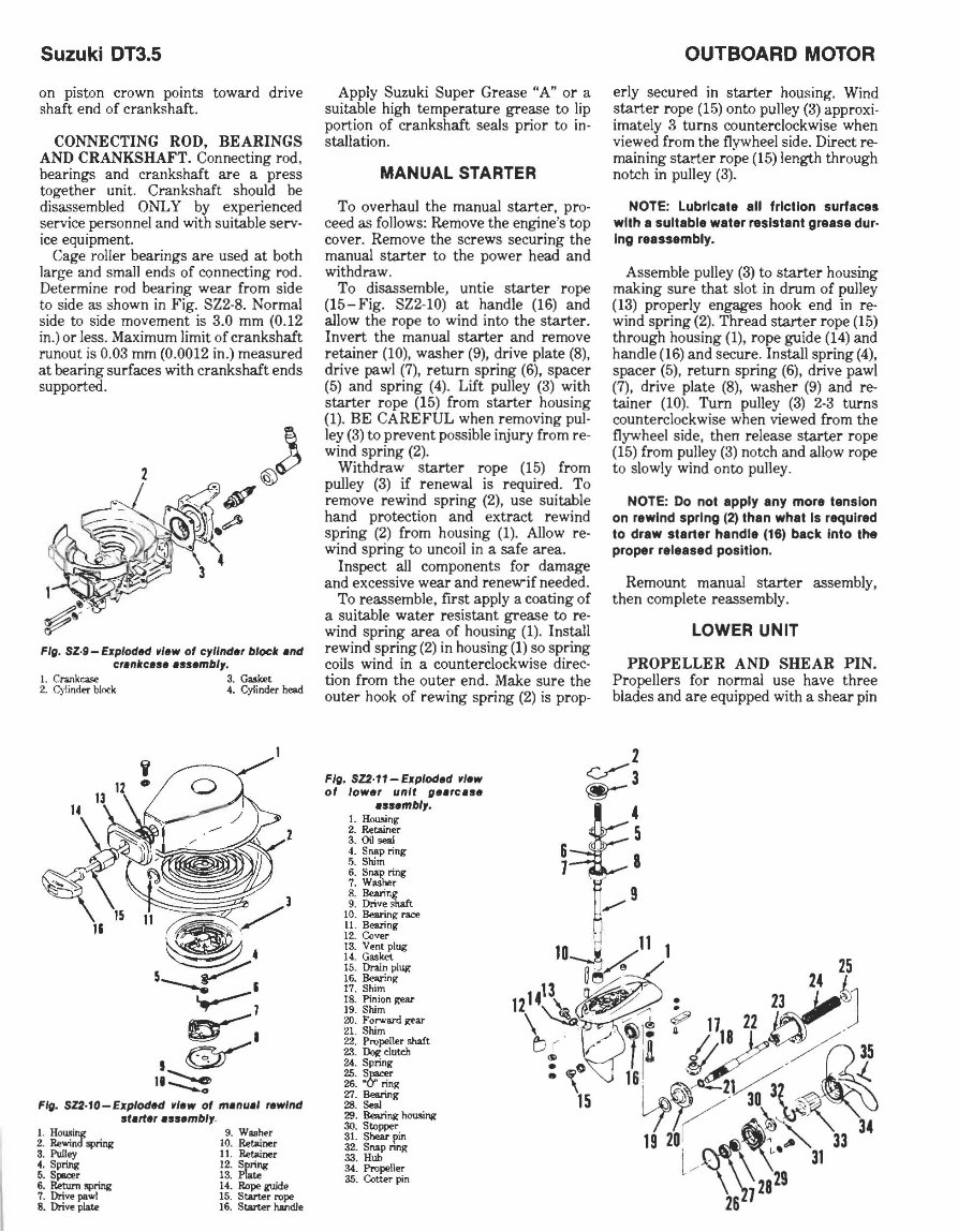
Suzuki DT3.5 on piston crown points toward drive shaft end of crankshaft. CONNECTING ROD, BEARINGS AND CRANKSHAFT. Connecting rod, bearings and crankshaft are a press together unit. Crankshaft should be disassembled ONLY by experienced service personnel and with suitable servo ice equipment. Cage roller bearings are used at both large and small ends of connecting rod. De termine rod bearing wear from side to side as shown in Fig. SZ2·8. Normal side to side movement is 3.0 mm (0 . 12 in.) or less. Maximum limit of crankshaft runou t is 0.03 mm (0.0012 in.) measured at bearing surfaces with crankshaft ends supported. Fig. sz·g - Exploded .Iew of cylinder block end cr.nlrc.se .s58mbl,. I. Crankca..c:.e 3. Gasket 2. Cylinder block 4. Cylinder head Fig. SZ2·10-Exploded .Iew of menuel rewind st."e, .ss8mbl,_ 1. HOIl.<Mg 2. Rewind spring 3. Pulley ~. Spring 6. Spo<:<r 6. Return "Pring 7. Drive pawl 8. Drive plate 9. Washer 10. Retainer 11 . Retainer 12. Spring 13. PIa .. 14. Rope guide 15. Starter rope 16. Stalter handle Apply Suzuki Super Grease "A" or a suitable high temperature grease to lip portion of crankshaft seals prior to in· stallation. MANUAL STARTER To overhaul the manual starter, pro· ceed as follows: Remove the engine's top cover. Remove the screws securing the manual starter to the power head and withdraw. To disassemble, untie starter r ope (15-Fig. SZ2·10) at handle (16) and allow the rope to wind into the starter. Invert the manual starter and remove retainer (10), washer (9), drive plate (8) , drive pawl (7) , return spring (6), spacer (5) and spring (4). Lift pulley (3) with starter rope (15) from starter housing (1). BE CAREFUL when removing pul · ley (3) to prevent possible injury from reo wind spring (2). Withdraw starter rope (15) from pulley (3) if renewal is required. To remove rewind spring (2), use suitable hand protection and extract rewind spring (2) from housing (1). Allow reo wind spring to uncoil in a safe area. Inspect all components for damage and excessive wear and renew-if needed. To reassemble, fIrst apply a coating of a suitable water resistant grease to reo wind spring area of housing (1). Install rewind spring (2) in housing (1) so spring coils wind in a counterclockwise direc- tion from the outer end. Make sure the outer hook of rewing spring (2) is prop- Fig. SZ2·11- Exploded .Iew of lower unit g •• re.a • • ss8mbl,. L HOW!.ing 2. IWtainer 3. Oil seal 4. Snap ring 5. Shim 6. Snap ring 7. Washer 8. IleJuing 9. Drive shaft 10. Bearing race 11. Bearing 12. O:lver 13. Vent plug 14. Gasket 15. Drain plug 16. Bearing 17. Shim 18. Pinion gear 19. Shim 20. Forward gear 21. Shim 22. Propeller shaft 23. Dot< clutch 24. Spring 25. Spacer 26. "0" ring '1:1. Bearing 28. Seal 29. Bearing hou.~ng 30. Stopper 31. Shear pin 32. Snap nng 33. Huh 34. Propeller 35. Cotter pin OUTBOARD MOTOR erly secured in starter housing. Wind starter rope (15) onto pulley (3) approxi- imately 3 turns counterclockwise when viewed from the flywheel side. Direct re- maining starter rope (15) length through notch in pulley (3). NOTE: Lubricate all friction surfaces with a suitable water resistant grease duro Ing reassembly. Assemble pulley (3) to starter housing making sure that slot in drum of pulley (13) properly engages hook end in re- wind spring (2). Thread starter rope (15) through housing (1), rope guide (14) and handle (16) and secure. Install spring (4), spacer (5) , return spring (6) , drive pawl (7), drive plate (8) , washer (9) and re- tainer (10). Turn pulley (3) 2-3 turns counterclockwise when viewed from the flywheel side, then release starter rope (15) from pulley (3) notch and allow rope to slowly wind onto pulley. NOTE: Do not apply any more tension on rewind spring (2) than what Is required to draw starter handle (16) back into the proper released position. Remount manual starter assembly, then complete reassembly. LOWER UNIT PROPELLER AND SHEAR PIN. Propellers for normal use have three blades and are equipped with a shear pin
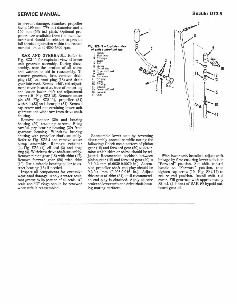
SERVICE MANUAL to prevent damage. Standard propeller has a 190 mm (7 ' ;' in .) diameter and a 150 mm (5 7 /0 in.) pitch. Optional pro- pellers are available from the manufac- turer and should be selected to provide full throttle operation within the recom- mended limits of 4800-5300 rpm. R&R AND OVERHAUL_ Refer to Fig. 822-11 for exploded view of lower unit gearcase assembly. During disas- sembly, note the location of all shims and ';ashers to aid in reassembly. To remove gearcase, first remove drain plug (15) and vent plug (13) and drain gear lubricant. Remove shift rod adjust- ment cover located at base of motor leg and loosen lower shift rod adjustment screw (10 - Fig. 822-12). Remove cotter pin (35 - Fig. 822-11), propeller (34) with hub (33) and shear pin (31). Remove cap screw and nut retaining lower unit gearcase and withdraw from drive shaft housing. Remove stopper (30) and bearing hou sing (29) retaining screws. Being careful, pry bearing housing (29) from gearcase housing. Withdraw bearing housing with propeller shaft assembly . Refer to Fig. 822-4 and remove water pump assembly. Remove retainer (2-Fig. 822-11), oil seal (3) and snap ring (4). Withdraw drive shaft assembly. Remove pinion gear (18) with shim (17). Remove forward gear (20) with shim (19). Use a suitable bearing puller to ex- tract bearing (16) if needed. Inspect all components for excessive wear aand damage. Apply a water resis- tant grease to lip portion of all seals. All seals and "0" rings should be renewed when unit is reassembled. Fig. SZ2·12-Exp/odod r/ow 01 shift conlrolllnkapo. 1. H.a.Mle 2. Shift lever 3. ·0" ri n g!'> 4. Shaft 5. Ball 6. Spring 7. Cotter pin~ 8. Upper li hift rod 9. Clamp 10. C5' ~e"'" 11. "0 nn~ 12. Guide 13. "0" rin~ 14 . WMhcr 15. Lo ..... er shift rod 16. Loclmut 17. Com Reassemble lower unit by reversing disassembly procedure while noting the following: Check mesh pattern of pinion gear (18) and forward gear (20) to deter- mine which shim or shims should be ad- justed. Recomended backlash between pinion gear (18) and forward gear (20) is 0.1-0.2 mm (0.0039-0.0079 in.). Assem- bled propeller shaft end play should be 0.2-0.4 mm (0.008-0.016 in.). Adjust thickness of shim (21) until recommend- ed end play is obtained. Apply silicone sealer to lower unit and drive shaft hous- ing mating surfaces. Suzuki DT3.5 With lower unit installed, adjust shift linkage by first ensuring lower unit is in "Forward" position. 8et shift control handle to "Forward" position, then tighten cap screw (lO-Fig. 822-12) to secure rod position. Install shift rod cover. Fill gearcase with approximately 85 mL (2 .9 ozs.) of 8AE 90 hypoid out- board gear oil.
Suzuki DT4 OUTBOARD MOTOR SUZUKI DT4 CONDENSED SERVICE DATA NOTE: Metric fasteners are used throughout outboard motor. TUNE-UP Hplrpm ...................... . ............... 4/5000 Bore .......... .. ............................ 50mm (1.97 in.) Stroke . . .................. . ................. 46 mm (1.81 in.) Displacement .......... .. .. . .. ........ .. . .... .. 90 cc (5.5 cu. in.) Spark Plug: NGK ...... .. ...... .. ..... .... . ........... BP6HS Electrode Gap .... . ......... ... .......... 0.6-0 .7 mm (0.024-0.028 in.) Ignition Type .. .. .. ... ......... .. ......... .. .. .. CD! Carburetor: Make .................. .. ..... . ... ......... Mikuni Model ................................... BV-18-15 Idle Speed (in gear) ... .. _. . _. . . .... ..... . . 850-900 rpm Fuel:Oil Ratio ..... .. . . See Text SIZES-CLEARANCES Piston Ring End Gap .. . ........... . ...... 0.15-0.35 mm (0.006-0_014 in.) Piston to Cylinder Clearance ............ 0_052-0_067 mm (0.0020-0.0026 in_) Piston Pin Diameter ..... __ .. _. _ ..... 11.995-12.000 mm (0.4 722-0.4 724 in.) SIZES-CLEARANCES CONT. Max. Crankshaft Runout at Main Bearing Journal .................. . _____ ... 0_05 mm (0.002 in.) Max . Connecting Rod Small End Side Shake ...... .... . .......... .. .. ...... __ 4.0 mm (0.16 in.) TIGHTENING TORQUES Power Head Mounting Screws ... .. . .. ....... 15-20 N· m (11-14 ft.-Ibs_) Crankcase ... .. .. .. . . _. __ ... __ .. ...... . __ .. 8-12 N • m (6-8 ft.-Ibs_) Flywheel Nut . .. . .... .. .. ... _. _ ........ . .. .. . 45 N'm (32 ft.-lbs.) Standard Screws: 5 mm ............ .. . . . , .. . .... ........... 2-4 N' m (1-3 ft.-Ibs .) 6mm .............................. , ..... 4-7N·m (3-5 ft.-Ibs.) 8mm .................................. 1O-16N·m (7-11 ft .-I bs.) 10mm ........... ... . ... ..... . ......... 22-35N·m (16-25 ft.-Ibs.) LUBRICATION The power head is lubricated by oil mixed with the fuel. Fuel:oil ratios should be 30: 1 during break-in of a new or rebuilt engine. For normal service, fuel:oil ratio should be 50: 1 on models prior to 1986 and 100: 1 on 1986 and later models when using Suzuki Out- board Motor Oil or a good quality NMMA certified TC- W engine oil. When using any other two-stroke oil, fuel:oil ratio should be 20: 1 during break-in and 30: 1 for normal service. Manufacturer recommends regular or unleaded au- tomotive gasoline having an 85 mini- mum octane rating. Gasoline and oil should be thoroughly mixed. turns out from a lightly seated position. Final atljustment should be made with engine at normal operating temperature and running in forward gear. Atljust throttle stop screw (9) so engine idles at approximately 850-900 rpm. Atljust pi- lot air screw so engine idles smoothly and will accelerate cleanly without hesi- tation. If necessary, readjust throttle stop screw to obtain 850-900 rpm idle ·s peed. Main fuel metering is controlled by main jet (2). Standard main jet size for normal operation is #97.5. Standard pi- lot jet (10) size is #45. To check float leve l. remove float bowl (12) and invert carburetor body (1) . Base of float (3) should be 12-14 mm (0.47 -0.55 in.) away from gasket surface of carburetor body with float bowl gas- ket removed. Atljust fl oat level by bend- ing float tang. The lower unit gears and bearings are lubricated by approximately 190 mL (6.4 ozs.) of SAE 90 hypoid outboard gear oil. Reinstall vent and fill plugs se- curely using a new gasket, if necessary, to ensure a water tight seal. FUEL SYSTEM CARBURETOR. A Mikuni BV-18-15 carburetor is used. Refer to Fig. SZ3-1 for exploded view. Initial setting of pi- lot air screw (6) should be 1 to 1-112 10 B 7 6 9 I 11 ~~~ 1 _ '--8-< 5--:'0" Fig. SZ3·1- Exploded vi ... 01 ""tunl 8'1-18-15 c.rbur.fOr. 1. Bods 2. Main jet 3. Float 4. Screw .5. Plug 6. Pilot air screw 7. Choke le ... ("t 8. Choke k.nob 9. Idle ~xre\lll 10. Pl/ot)et 11. <4skl't 12. Float bowl FUEL PUMP. A diaphragm fuel pump (Fig_ SZ3-2) is mounted on the side of power head cylinder block and is actuated by pressure and vacuum pulsa- tions from the engine crankcase. When servicing pump, defective or questionable parts should be renewed. Diaphragm should be renewed if air leaks or cracks are found, or if deterioration is evident. SPEED CONTROL LINKAGE. Engine speed is controlled by position of throttle linkage. Ignition advance is electronically controlled. A twist grip at the steering handle is used to control throttle settings. •
1983-1987 Suzuki 9.9HP Outboard (DT9.9) OEM Service & Repair Manual
The 1983-1987 Suzuki 9.9HP Outboard (DT9.9) OEM Service & Repair Manual is the factory reference for keeping this small but dependable two-stroke outboard in proper running condition. Designed for both professional marine technicians and hands-on boat owners, it provides the step-by-step details needed to handle everything from routine maintenance to full rebuilds.
Inside, you’ll find complete specifications, service intervals, and procedures for engine disassembly, inspection, and reassembly. The manual also covers fuel system cleaning and adjustment, lubrication service, and cooling system troubleshooting to ensure proper water flow and temperature control. Gearcase inspection, propeller shaft servicing, and shift linkage adjustments are also included, with clear sequences to make the work straightforward.
Whether you’re dialing in performance after a season on the water or troubleshooting a no-start condition, this manual gives you the exact procedures Suzuki published for the DT9.9. It’s a practical, reliable guide that keeps your outboard running strong for years.
Printable: Yes Language: English Compatibility: Pretty much any electronic device, incl. PC & Mac computers, Android and Apple smartphones & tablet, etc. Requirements: Adobe Reader (free)
Recently Viewed
5,521,897Happy Clients
2,594,462eManuals
1,120,453Trusted Sellers
15Years in Business
Price:
Actual Price:
1983-1987 Suzuki 9.9HP Outboard (DT9.9) OEM Service & Repair Manual