1967 Sea King Outboard Motors Factory Service & Work Shop Manual
What's Included?
Lifetime Access
Fast Download Speeds
Online & Offline Access
Access PDF Contents & Bookmarks
Full Search Facility
Print one or all pages of your manual
RYS LER ard SERVICE MANUAL 6 and 9.2 H.P. OUTBOARD MOTORS CHRYSLER OUTBOARD CORPORATION HARTFORD, WISCONSIN, U. 5. A. CHRYSLER CANADA OUTBOARD LTD. BARRIE, ONTARIO, CANADA www.Repairmanuals4u.com
www.Repairmanuals4u.com
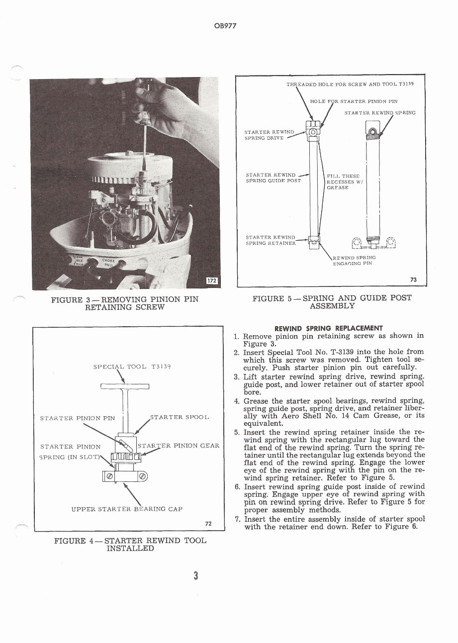
FIGURE 3 - REMOVING PINION PIN RETAINING SCREW THREADED HOLE FOR SCREW AND TOOL T3139 STARTER REWIND SPRING SPRING DRIVE STARTER REWIND / FILL THESE SPRING GUIDE POST RECESSES W/ ' RE WIND SPRING ENGAGING PIN 73 FIGURE 5 -SPRING AND GUIDE POST ASSEMBLY SPECIAL TOOL T3139 STARTER PINION PIN STARTER SPOOL STARTER PINION ER PINION GEAR SPRING (IN SLOT) UPPER STARTER BEARING CAP 72 n REWIND SPRING REPLACEMENT 1. Remove pinion pin retaining screw as shown in Figure 3. 2. Insert Special Tool No. T-3139 into the hole from which this screw was removed. Tighten tool se- curely. Push starter pinion pin out carefully. 3. Lift starter rewind spring drive, rewind spring. guide post, and lower retainer out of starter spool bore. 4. Grease the starter spool bearings, rewind spring, spring guide post, spring drive, and retainer liber- ally with Aero Shell No. 14 Cam Grease, or its equivalent. 5. Insert the rewind spring retainer inside the re- wind spring with the rectangular lug toward the flat end of the rewind spring. Turn the spring re- tainer until the rectangular lug extends beyond the flat end of the rewind spring. Engage the lower eye of the rewind spring with the pin on the re- wind spring retainer. Refer to Figure 5. 6. Insert rewind spring guide post inside of rewind spring. Engage upper eye of rewind spring with pin on rewind spring drive. Refer to Figure 5 for proper assembly methods. 7. Insert the entire assembly inside of starter spool with the retainer end down. Refer to Figure 6. FIGURE 4 - STARTER REWIND TOOL INSTALLED www.Repairmanuals4u.com
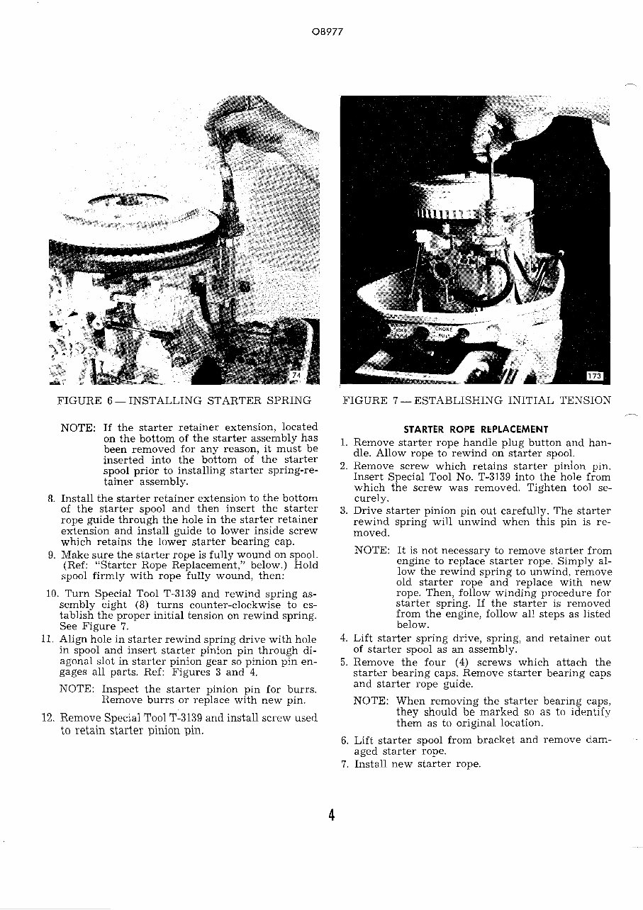
FIGURE 6 - INSTALLING STARTER SPRING FIGURE 7 - ESTABLISHING INITIAL TENSION NOTE: If the starter retainer extension, located on the bottom of the starter assembly has been removed for any reason, it must be inserted into the bottom of the starter spool prior to installing starter spring-re- tainer assembly. 8. Install the starter retainer extension to the bottom of the starter spool and then insert the starter rope guide through the hole in the starter retainer extension and install guide to lower inside screw which retains the lower starter bearing cap. 9. Make sure the starter rope is fully wound on spool. (Ref: "Starter Rope Replacement," below.) Hold spool firmly with rope fully wound, then: 10. Turn Special Tool T-3139 and rewind spring as- sembly eight (8) turns counter-clockwise to es- tablish the proper initial tension on rewind spring. See Figure 7. 11. Align hole in starter rewind spring drive with hole in spool and insert starter pinion pin through di- agonal slot in starter pinion gear so pinion pin en- gages all parts. Ref: Figures 3 and 4. NOTE: Inspect the starter pinion pin for burrs. Remove burrs or replace with new pin. 12. Remove Special Tool T-3139 and install screw used to retain starter pinion pin. STARTER ROPE REPLACEMENT 1. Remove starter rope handle plug button and han- dle. Allow rope to rewind on starter spool. 2. Remove screw which retains starter pin. Insert Special Tool No. T-3139 into the hole from which the screw was removed. Tighten tool se- curely. 3. Drive starter pinion pin out carefully. The starter rewind spring will unwind when this pin is re- moved. NOTE: It is not necessary to remove starter from engine to replace starter rope. Simply al- low the rewind spring to unwind, remove old starter rope and replace with new rope. Then, follow winding procedure for starter spring. If the starter is removed from the engine, follow all steps as listed below. 3. Lift starter spring drive, spring, and retainer out of starter spool as an assembly. 5. Remove the four (4) screws which attach the starter bearing caps. Remove starter bearing caps and starter rope guide. NOTE: When removing the starter bearing caps, they should be marked so as to identify them as to original location. 6. Lift starter spool from bracket and remove dam- -- aged starter rope. 7. Install new starter rope. www.Repairmanuals4u.com
.- . NOTE: If the starter rope is cut for any reason, 1. Remove starter pinion gear and spring from start- the frayed or cut portion of the rope must er. be seared to prevent it from unriveling. 2. Remove pinion spring from gear. To do this, light a match and burn end 3. Compress pinion spring until ends contact each of rope to seal nylon fibers. other. This will increase the tension on the starter IMPORTANT: IF THE STARTER ROPE pinion gear. SHOULD HAVE TO BE CUT FOR ANY 4. Lubricate groove in pinion gear with Rykon grease, REASON, DO NOT REMOVE MORE T-2961, and reinstall spring. THAN INCH, AS THE STNtTER RE- 5. Reinstall starter pinion and rewind starter. 'OIL BE ADVERSELY 6. Check starter and full throttle operation. If pin- AFFECTED. ion is too tight, simply spread spring ends until 8. Rewind new starter rope on spool. spring has firm drag, but does not cause a sluggish 9. Inspect the starter pinion gear for wear. If worn excessively, replace. The starter pinion spring should have only a light tension on the gear, as 6 - 9.2 H.P. MANUAL START the function of the spring is to apply only enough 1966 MODELS tension to prevent the gear from turning with the ELECTRICAL shaft. Lubricate the shaft portion of the starter A. Breaker Point spool before installing the starter pinion gear. 10. Lubricate the bearing surface of the starter spool, Remove nut. then assemble spool and rope to the carburetor 2. Install flywheel knock-off nut to crmkshaft. adapter flange (or mounting bracket). See list below for proper tool number. Turn knock-off nut down to within two turns of the NOTE: Be sure to install the starter retainer ex- flywheel. Lift up on edge of flywheel when tension to the bottom of the starter spool striking nut. Strike knock-off nut with a medi- and then insert the starter rope guide um eight hammer. The blow should be centered through the hole in the starter retainer as much as possible. Do not use a heavy ham- extension and install guide to lower inside mer or strike too hard, as possible damage to screw which retains the lower starter the crankshaft and bearings could result. bearing cap. a. 6 and 9.2 H.P. Models T-18091. 11. Install the starter bearing caps, making sure that 3. Inspect the breaker point contact surfaces vis- match marks are together. The leg of the starter ually. If they are burned or pitted they should pinion spring should be inserted in the slot formed be replaced. Do not file breaker points, RE- by the upper bearing cap. Ref: Figure 4. PLACE WITH NEW PARTS. NOTE: The upper bearing cap c+n be identifed NOTE: IF THE BREAKER POINTS ARE EX- by the chamfer adjacent to the bearing. CESSIVELY PITTED, CHECK THE After bearing cap screws have been tightened, the CONDENSER, AS THIS CONDITION starter spool should rotate freely without binding. IS USUALLY CAUSED BY A WEAK The spool should have about 1/16" end float. OR DEFECTIVE CONDENSER. 12. Lubricate the starter rewind spring and insert en- 4. When setting breaker points after a number tire spring assembly inside spool with retainer end of hours of operation, they must be cleaned be- down. Make sure retainer extknsion is inserted in fore adjusting acording to the following pro- lower end of spool before installing rewind spring. cedure: 13: Pull starter rope through engine control panel and a. A small strip of 320 grit emery cloth, or its attach starter handle and plain washer. Tie knot equivalent, is folded and inserted between in end of starter rope and pull knot securely into the points. The points are held closed on the cavity of handle. Install plug button to starter emery cloth, and the cloth rotated, using the handle. points as a pivot. The points are OPENED 14. Perform Steps 8, 9, 10, 11 and 12 as listed under before removing the cloth, and then held "Rewind Spring Replacement," this section. open while inserting a clean piece of hard NOTE surface cardboard. Hold the points closed on If full throttle operation cannot be obtained, the the cardboard, and rotate the cardboard us- probable cause is the starter pinion gear restricting ing the points as a pivot, to remove oxide the throttle cam operation by riding up on the starter and other foreign matter loosened by the spool shaft. This condition can be corrected as fol- emery cloth. The cardboard should be used lows: in several spots until no further dirt can be removed. b. Adjust breaker points as outlined above. www.Repairmanuals4u.com
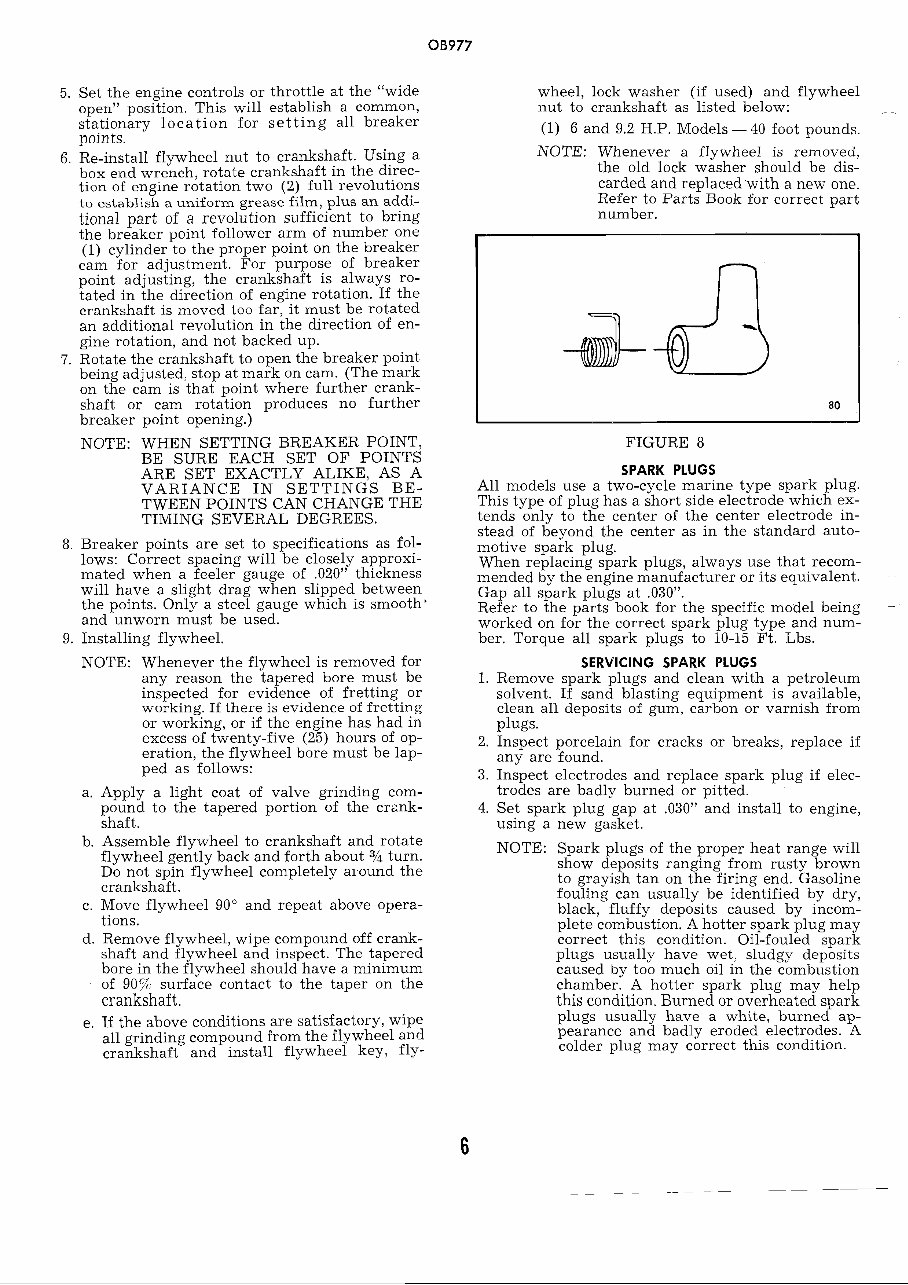
5. Set the engine controls or throttle at the "wide open" position. This will establish a common, stationary location for setting all breaker points. 6. Re-install flywheel nut to crankshaft. Using a box end wrench, rotate crankshaft in the direc- tion of engine rotation two (2) full revolutions to establish a uniform grease film, plus an addi- tional part of a revolution sufficient to bring the breaker point follower arm of number one (1) cylinder to the proper point on the breaker cam for adjustment. For purpose of breaker point adjusting, the crankshaft is always ro- tated in the direction of engine rotation. If the crankshaft is moved too far, it must be rotated an additional revolution in the direction of en- gine rotation, and not backed up. 7. Rotate the crankshaft to open the breaker point being adjusted, stop at mark on cam. (The mark on the cam is that point where further crank- shaft or cam rotation produces no further breaker point opening.) NOTE: WHEN SETTING BREAKER POINT, BE SURE EACH SET OF POINTS ARE SET EXACTLY ALIKE, AS A VARIANCE IN SETTINGS BE- TWEEN POINTS CAN CHANGE THE TIMING SEVERAL DEGREES. 8. Breaker points are set to specifications as fol- lows: Correct spacing will be closely approxi- mated when a feeler gauge of .020" thickness will have a slight drag when slipped between the points. Only a steel gauge which is smooth' and unworn must be used. 9. Installing flywheel. NOTE: Whenever the flywheel is removed for any reason the tapered bore must be inspected for evidence of fretting or working. If there is evidence of fretting or working, or if the engine has had in excess of twenty-five (25) hours of op- eration, the flywheel bore must be lap- ped as follows: a. Apply a light coat of valve grinding com- pound to the tapered portion of the crenk- shaft. b. Assemble flywheel to crankshaft and rotate flywheel gently back and forth about 3/4 turn. Do not spin flywheel completely ai.ound the crankshaft. c. Move flywheel 90" and repeat above opera- tions. d. Remove flywheel, wipe compound off crank- shaft and flywheel and inspect. The tapered bore in the flywheel should have a minimum of 90% surface contact to the taper on the crankshaft. e. If the above conditions are satisfactory, wipe all grinding compound from the flywheel and. crankshaft and install flywheel key, fly- wheel, lock washer (if used) and flywheel nut to crankshaft as listed below: - (1) 6 and 9.2 H.P. Models - 40 foot pounds. NOTE: Whenever a flywheel is removed, the old lock washer should be dis- carded and replaced with a new one. Refer to Parts Book for correct part number. FIGURE 8 SPARK PLUGS All models use a two-cycle marine type spark plug. This type of plug has a short side electrode which ex- tends only to the center of the center electrode in- stead of beyond the center as in the standard auto- motive spark plug. When replacing spark plugs, always use that recom- mended by the engine manufacturer or its equivalent. Gap all spark plugs at .030". Refer to the parts book for the specific model being - worked on for the correct spark plug type and num- ber. Torque all spark plugs to 10-15 Ft. Lbs. SERVICING SPARK PLUGS 1. Remove spark plugs and clean with a petroleum solvent. If sand blasting equipment is available, clean all deposits of gum, carbon or varnish from plugs. 2. Inspect porcelain for cracks or breaks, replace if any are found. 3. Inspect electrodes and replace spark plug if elec- trodes are badly burned or pitted. 4. Set spark plug gap at ,030" and install to engine, using a new gasket. NOTE: Spark plugs of the proper heat range will show deposits ranging from rusty brown to grayish tan on the firing end. Gasoline fouling can usually be identified by dry, black, fluffy deposits caused by incom- plete combustion. A hotter spark plug may correct this condition. Oil-fouled spark plugs usually have wet, sludgy deposits caused by too much oil in the combustion chamber. A hotter spark plug may help this condition. Burned or overheated spark plugs usually have a white, burned ap- pearance and badly eroded electrodes. A colder plug may correct this condition. www.Repairmanuals4u.com
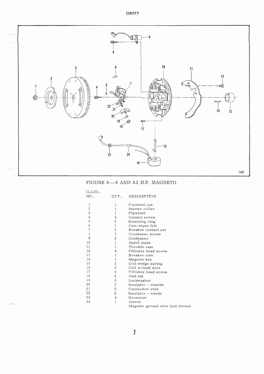
COIL REPLACEMENT The coils are held in place with coil wedge springs which pass between the coil and core. To remove coil, disconnect primary and secondary lead wires and pry on end of coil wedge spring attached to coil core. It may be necessary to bend one of the coil core lamina- tions to remove coil. After removing spring and bend- ing lamination, using two screwdrivers, pry coil from core. NOTE: When replacing coil, bend core lamination down to insure against the coil moving out and striking the flywheel. CONDENSER REPLACEMENT The function of the ignition condenser is to reduce point arc and bring primary current to a halt when the points open. Therefore, a condenser that leaks, or one that has little or too high a capacity will have a direct bearing on breaker point life and consecluently engine p~rformance To remove condenser, disconnect lead wire attached to breaker point and remove screw securing it to sta- tor plate. 6 AND 9.2 H.P. MANUAL START MODELS 1. Remove flywheel using proper knock-off nut. 2. Remove four (4) screws which retain magneto to stator ring. 3. Remove spark plug lead wire and magneto ground wire from top forward screw on fuel pump. 4. Remove magneto shorting wires from clamp on top of carburetor adapter flange if used. 5. Remove magneto control link. 6. Lift magneto up and off the engine. '7. If power head repairs are to be made, remove magneto cam and key. MAGNETO ASSEMBLY 1. Lubricate all moving parts, linkages, magneto pilot bore, stator plate, and cam wiper felts with Rykon #2EP, Part No. T-2961, when reassembling. 2. Install magneto breaker cam and key, if removed. Install cam with arrow or part number "up". 3. Reassemble magnetos in reverse order as listed above. 4. Torque flywheel nut. The following instructions are to be used in conjunc- tion with the wiring diagram following these instruc- tions. Refer to the parts book for the model being worked on for methods of assembly, hardware sizes and lo- cations. www.Repairmanuals4u.com
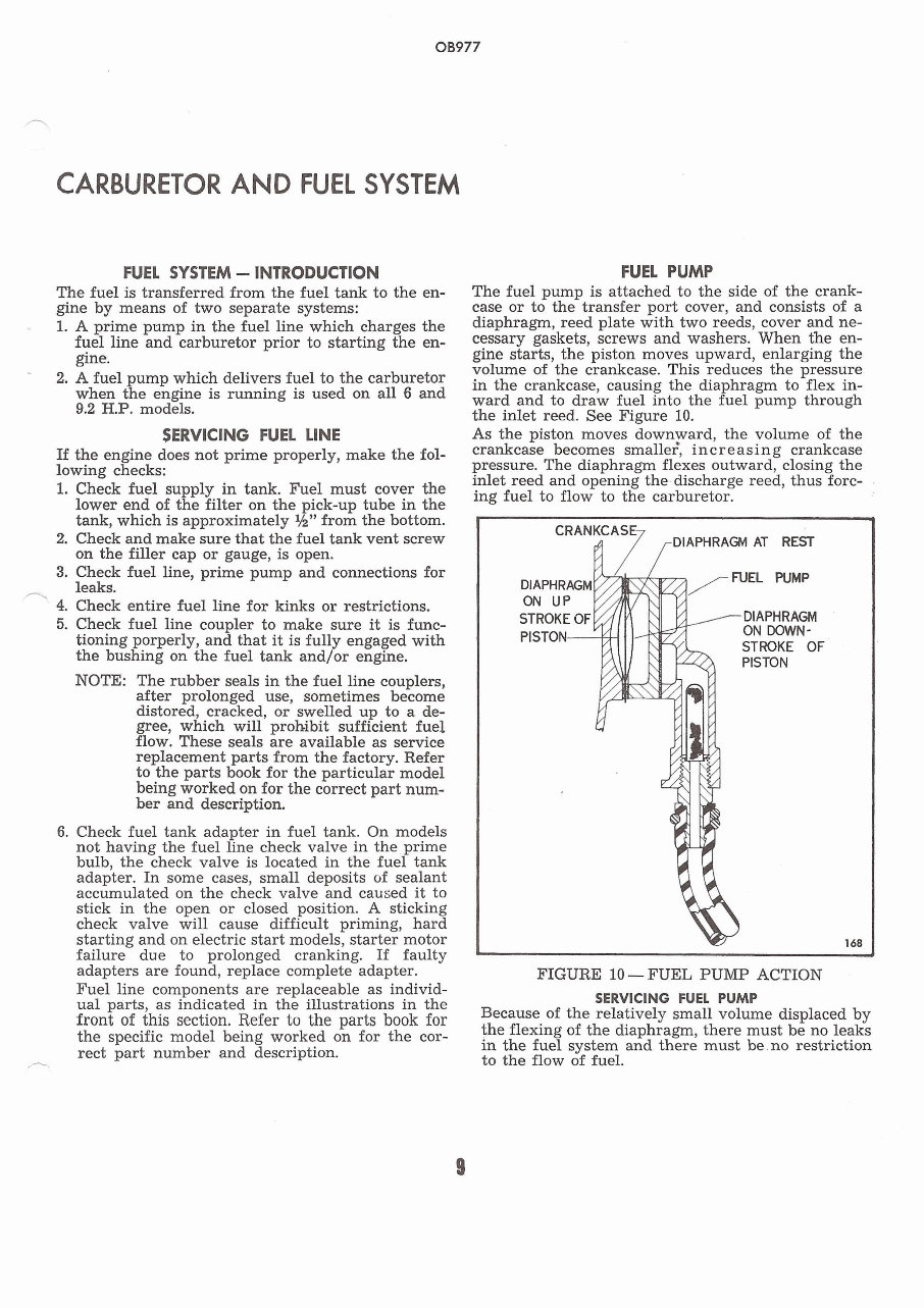
CARBURETOR AND FUEL SYSTEM FUEL SYSTEM - INTRODUCTION The fuel is transferred from the fuel tank to the en- gine by means of two separate systems: - 1. A prime pump in the fuel line which charges the fuel line and carburetor prior to starting the en- gine. 2. A fuel ump which delivers fuel to the carburetor when t !i e engine is running is used on all 6 and 9.2 H.P. models. SERVICING FUEL LINE If the engine does not prime properly, make the fol- lowing checks: 1. Check fuel supply in tank. Fuel must cover the lower end of the filter on the pick-up tube in the tank, which is approximately M" from the bottom. 2. Check and make sure that the fuel tank vent screw on the filler cap or gauge, is open. 3. Check fuel line, prime pump and connections for n leaks. 4. Check entire fuel line for kinks or restrictions. 5. Check fuel line coupler to make sure it is func- tioning porperly, and that it is fully engaged with the bushing on the fuel tank and/or engine. NOTE: The rubber seals in the fuel line couplers, after prolonged use, sometimes become distored, cracked, or swelled up to a de- gree, which will prohibit sufficient fuel flow. These seals are available as service replacement parts from the factory. Refer to the parts book for the particular model being worked on for the correct part num- ber and description. 6. Check fuel tank adapter in fuel tank. On models not having the fuel line check valve in the prime bulb, the check valve is located in the fuel tank adapter. In some cases, small deposits of sealant accumulated on the check valve and caused it to stick in the open or closed position. A sticking check valve will cause difficult priming, hard starting and on electric start models, starter motor failure due to prolonged cranking. If faulty adapters are found, replace complete adapter. Fuel line components are replaceable as individ- ual parts, as indicated in the illustrations in the front of this section. Refer to the parts book for the specific model being worked on for the cor- - rect part number and description. FUEL PUMP The fuel pump is attached to the side of the crank- case or to the transfer port cover, and consists of a diaphragm, reed plate with two reeds, cover and ne- cessary gaskets, screws and washers. When the en- gine starts, the piston moves upward, enlarging the volume of the crankcase. This reduces the pressure in the crankcase, causing the diaphragm to flex in- ward and to draw fuel into the fuel pump through the inlet reed. See Figure 10. As the piston moves downyard, the volume of the crankcase becomes smaller, increasing crankcase pressure. The diaphragm flexes outward, closing the inlet reed and opening the-discharge reed, thus forc- ing fuel to flow to the carburetor. DIAPHRAGM FIGURE 10 -FUEL PUMP ACTION SERVICING FUEL PUMP Because of the relatively small volume displaced by the flexing of the diaphragm, there must be no leaks in the fuel system and there must be.no restriction to the flow of fuel. www.Repairmanuals4u.com
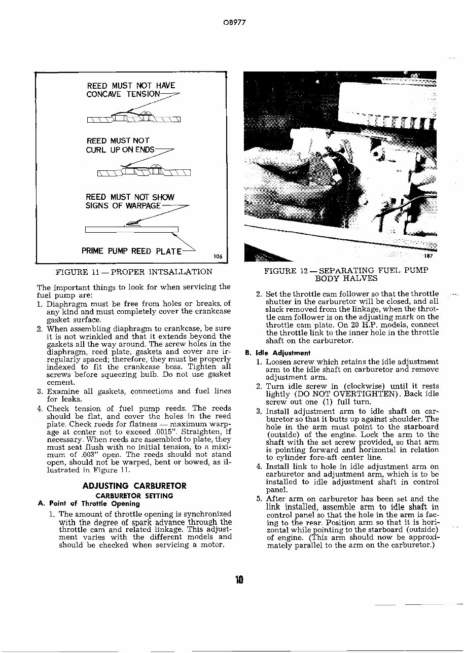
FIGURE 11 - PROPER INTSALLATION . The important things to look for when servicing the fuel pump are: 1. Diaphragm must be free from holes or breaks, of any kind and must completely cover the crankcase gasket surface. 2. When assembling diaphragm to crankcase, be sure it is not wrinkled and that it extends beyond the gaskets all the way around. The screw holes in the diaphragm, reed plate, gaskets and cover are ir- regularly spaced; therefore, they must be properly indexed to fit the crankcase boss. Tighten all screws before squeezing bulb. Do not use gasket cement. 3. Examine all gaskets, connections and fuel lines for leaks. 4. Check tension of fuel pump reeds. The reeds should be flat, and cover the holes in the reed plate. Check reeds for flatness - maximum warp- age at center not to exceed .0015". Straighten, if necessary. When reeds are assembled to plate, they must seat flush with no initial tension, to n mixi- mum of .003" open. The reeds should not stand open, should not be warped, bent or bowed, as il- lustrated in Figure 11. REED MUST NOT HAVE CONCAVE TENSION REED MUST NOT CURL UP ON ENDS REED MUST NCJr SHOW SIGNS OF WARPAGE PRIME PUMP REED PLATE 106 ADJUSTING CARBURETOR CARBURETOR SETTING A. Point of Throttle Opening 1. The amount of throttle opening is synchronized with the degree of spark advance through the throttle cam and related linkage. This adjust- ment varies with the different models and should be checked when servicing a motor. FIGURE 12 - SEPARATING FUEL PUMP BODY HALVES 2. Set the throttle cam follower so that the throttle - shutter in the carburetor will be closed, and all slack removed from the linkage, when the throt- tle cam follower is on the adjusting mark on the throttle cam plate. On 20 H.P. models, connect the throttle link to the inner hole in the throttle shaft on the carburetor. B. Idle Adjustment 1. Loosen screw which retains the idle adjustment arm to the idle shaft on carburetor and remove adjustment arm. 2. Turn idle screw in (clockwise) until it rests lightly (DO NOT OVERTIGHTEN). Back idle screw out one (1) full turn. 3. Install adjustment arm to idle shaft on car- buretor so that it butts up against shoulder. The hole in the arm must point to the starboard (outside) of the engine. Lock the arm to the shaft with the set screw provided, so that arm is pointing forward and horizontal in relation to cylinder fore-aft center line. 4. Install link to hole in idle adjustment arm on carburetor and adjustment arm, which is to be installed to idle adjustment shaft in control panel. 5. After arm on carburetor has been set and the link installed, assemble arm to idle shaft in control panel so that the hole in the arm is fac- ing to the rear. Position arm so that it is hori- zontal while pointing to the starboard (outside) of engine. (This arm should now be approxi- mately parallel to the arm on the carburetor.) www.Repairmanuals4u.com
Upon purchasing this manual, you will receive a .PDF file containing an email contact. After contacting us, you will receive a reply with a link to access the manual for your 1967 Sea King Outboard Motors.
This comprehensive manual covers every aspect of your machine, providing detailed guidance on every nut and bolt. With hundreds of pages, it offers solutions for various issues, from simple tasks like an oil change to more complex procedures like a transmission swap. The manual includes numerous illustrations to assist you and features easy-to-understand text throughout.
Utilize the search function to navigate the manual efficiently and print the necessary pages as needed. This Factory Service Repair Manual is designed to walk you through the fundamentals of maintenance and repair, providing step-by-step instructions to empower you with the knowledge that factory-trained technicians possess. By utilizing the insights in this service repair manual, any owner can confidently make informed decisions regarding the maintenance and repair of their machine.
Rest assured, in addition to the high-quality service manual, we are committed to providing excellent customer service, ensuring your satisfaction with your purchase.
Recently Viewed
5,521,897Happy Clients
2,594,462eManuals
1,120,453Trusted Sellers
15Years in Business
Price:
Actual Price:
1967 Sea King Outboard Motors Factory Service & Work Shop Manual