MINN KOTA AUTOPILOT PD AP Models TROLLING MOTOR Full Service & Repair Manual
What's Included?
Lifetime Access
Fast Download Speeds
Online & Offline Access
Access PDF Contents & Bookmarks
Full Search Facility
Print one or all pages of your manual
Minn Kota Repair Manual 01/15/04 i M M i i n n n n K K o o t t a a S S e e r r v v i i c c e e M M a a n n u u a a l l This manual is designed to assist in basic trouble shooting procedures for MinnKota trolling motors. Table of Contents Page Safety Warnings ii Trouble Shooting Tips iii Section 1. Hand-Control Models with a Speed Coil 1-1 (5-speed models) Section 2. Hand-Control Models with a Printed Circuit Board 2-1 (Variable-speed models) Section 3. PowerDrive (PD) Models 3-1 (Corded foot pedal, non-AutoPilot, non-Genesis models) Section 4. AutoPilot (PD/AP) Models 4-1 (Corded foot pedal, non-Genesis models) Part I – motors prior to model year 2001 page 4-1 Part II – 2001 and later motors page 4-8 Section 5. Cordless PowerDrives and AutoPilot Models 5-1 (Radio-frequency controlled models, manufactured between 1996-1999) Section 6. Foot-Control Cable Steer Models with a Speed Coil 6-1 (5-speed Maxxum and All Terrain units) Section 7. Foot-Control Cable Steer Models with a Control Board 7-1 (Variable-speed Maxxum and All Terrain units) Section 8. PowerUp Lifts, Trims, and Tilts 8-1 (Models manufactured between 1996-2002) Section 9. Depth Finder Interference 9-1 Section 10. Vantage Motors 10-1 Section 11. Genesis Motors 11-1 Section 12. Minn Kota Universal Sonar 12-1 Section 13. Lower Unit / Motor Assembly 13-1 (includes instructions to remove motor assembly from composite tube) Section 14. Engine Mount (EM) & Neptune (EP) 14-1 Section 15. DeckHand Electric Anchors 15-1 Section 16. CoPilot Wireless Accessory 16-1 Section 17. 3X Steering 17-1
Minn Kota Repair Manual 10/31/02 ii SAFETY WARNINGS To prevent possible eye injury, always wear SAFETY GLASSES while servicing motors. Remove propeller from motor during test procedures to eliminate chances of being cut by rotating blades. Do not run motor out of water for more than a minute at a time. The motor assemblies (and speed coils) are designed to dissipate heat through the motor shell into water. The armature seals can also dry out. Follow all battery charging precautions to eliminate chances of the escaping fumes exploding.
Minn Kota Repair Manual 10/31/02 iii Trouble Shooting Tips… With all the new features and models being added to our Minn Kota line, motor troubleshooting and repair can be quite complicated. However, with circuit board costs rising, it is more important than ever to correctly diagnose the problem before replacing parts. Here are a few trouble shooting suggestions: If possible, locate the failure before replacing any parts. Sometimes disassembly fixes the problem (pinched wires, poor connections, etc…). Look at the wiring as closely as you would the control board. There are as many problems with wires and connectors as with defective control boards. Check the coil cords on AutoPilot models. An open wire here will look like a bad board. On control boards with clear sleeves around the quick disconnects, be sure the female connector does not slip down beside the male connector. It may feel like the connector went on properly, but this connection will fail. For quick troubleshooting, use a 12-volt light bulb (automotive dome or brake light) with wires and alligator clips. Clip it to the board output and vary the speed to see if the board is working. A voltmeter on the output can sometimes be misleading. The control board needs some kind of load to work correctly. If you have replaced a board in the same motor more than once, this is probably a symptom of a larger problem. Check the wiring in the lower unit. (Shorts on the motor wires will cause board failures and shorts in PowerDrive drive housings will cause foot pedal board failures.) We still see control boards replaced under warranty that are NOT defective. To help us control costs to all our customers and to ensure that we will honor your warranty reimbursement claim, please be certain the board is defective. On AutoPilot motors, seldom do both boards fail at the same time. Please double check.
Hand-Control w/Speed Coil Repair Manual 10/31/02 1- 1 Section 1. Hand-Control Models with a Speed Coil Case I. Motor fails to operate (on any speed). Step 1. Check to ensure proper voltage. Inspect all battery connection, trolling motor plug (if installed), and any butt splice connections in battery leadwire for corrosion and security. Step 2. Check to see if lower unit runs. A. Connect battery lead wire to battery. B. Disconnect the black battery leadwire from the switch and connect it directly to the black brush lead. C. Disconnect the red battery leadwire from the switch and touch it directly to the red brush lead. C-1. If motor does run, proceed to Step 3. C-2. If motor does not run, a problem exists in the lower unit. Check the lower unit for voltage at the brushes, water damage, brushes not making proper contact, or an open or shorted armature. Repair as needed and test motor for proper operation. Step 3. If unit being serviced is not a 12/24-volt model, proceed to Step 4. If unit being serviced is a 12/24-volt model, check 12/24 switch for continuity. Terminal A Terminal C Terminal B (front side of switch) (back side of switch) A. Turn the 12/24 switch to 12-volt ON position. Check for continuity between the common “C” terminal and the “A” terminal. A-1. If no continuity is noted, replace the 12/24 switch and test motor for proper operation. A-2. If continuity is observed, proceed to Step 3B. B. Turn switch to 24-volt ON. Check for continuity between the common terminal (C) and terminal (B). B-1. If no continuity is observed, replace 12/24 switch and test motor for proper operation. B-2. If continuity is observed, proceed to Step 4. Step. 4 Speed switch is defective. Replace the speed switch. Test motor for proper operation. Case II. Motor operates on some speeds, not on others. Step 1. Check to see if all wires are securely attached to the proper switch terminals. Step 2. Check speed coil functionality. A. Connect battery lead wire to battery. B. Disconnect the black battery lead from the switch and connect it directly to the black brush lead. C. Disconnect the red battery lead from the switch and touch it to each colored speed coil wire at the switch terminals, one at a time. The motor should run as you make each connection. D. If the motor fails to run as you touch any of the colored speed coil wires, the problem is either: (1) the speed coil is faulty and needs to be replaced; or (2) the speed coil jumper wire is not connected to the back of the brush plate (in the lower unit). D-1. If the motor runs as you touch the red battery lead to some of the colored speed coil wires, but not all the speed coil wires, the speed coil is faulty and needs to be replaced. D-2. If the motor runs as you touch the red battery lead to each speed coil wire, proceed to Step 3. Step 3. Speed switch is defective. Replace Speed switch. Test motor for proper operation. 24v OFF 12v
Hand-Control w/Control Board Repair Manual 01/20/04 2- 1 Section 2. Hand-Control Models with a Printed Circuit Board Case I. Motor runs intermittently (cuts in and out, fails to run in either forward or reverse, or kicks from forward into reverse). Step 1. Check to ensure proper voltage and polarity at battery (red +, black -). Inspect all battery connections, trolling motor plug (if installed), and any butt splice connections in battery leadwire for corrosion and security. Step 2. Check to see if lower unit runs properly. A. Connect battery lead wire to battery. B. Disconnect the black battery lead from the control board and connect it directly to the black brush lead. C. Disconnect the red battery lead from the control board and touch it directly to the red brush lead. The motor should run. C-1. If motor does not run, a problem exists in the lower unit. Check the lower unit for voltage at the brushes, water in the lower unit, worn brushes, or an open or shorted armature. C-2. If the motor does run, go to Step 3. Step 3. Units with soft-pots only: Check soft-pot (P/N 2364005) on control board. A. Visually check soft-pot for collapsed dome switches or a break down of the silver conductive layer for the speed control. If necessary, solder on replacement soft-pot (P/N 2364005) and test motor for proper operation (per the procedure shown in Service Bulletin dated 1/12/99). Case II. Motor fails to operate. Step 1. Check to ensure proper voltage and polarity at battery (red +, black -). Inspect all battery connections, trolling motor plug (if installed), and any butt splice connections in battery leadwire for corrosion and security. Step 2. Check to see if all wires are securely attached to the proper control board terminals. Check for corroded connections. Step 3. Check to see if lower unit operates. A. Connect battery lead wire to battery. B. Disconnect the black battery lead from the control board and connect it directly to the black brush lead. C. Disconnect the red battery lead from the control board and touch it directly to the red brush lead. The motor should run. C-1. If motor does not run, a problem exists in the lower unit. Check the lower unit for voltage at the brushes, water in the lower unit, worn brushes, or an open or shorted armature. C-2. If the motor does run, go to Step 4. Step 4. Check control board. MODELS WITH A SOFT-POT A. Remove soft-pot from handle assembly and ensure actuator pin and actuator spring are making proper contact on the silver conductor layer of the soft-pot. Visually inspect soft-pot for collapsed dome switches and excess wear on silver conductive layer of soft-pot. If
Hand-Control w/Control Board Repair Manual 01/20/04 2- 2 necessary, solder on replace soft-pot (P/N 2364005) and test motor for proper operation (per the procedure shown in Service Bulletin dated 1/12/99). B. Operate control board manually (without handle assembly actuators). With battery and brush leads attached to proper terminals of the control board, activate switch in upper right hand corner and run fingertip around silver conductive layer. The motor should be varying in speed as you apply pressure to the forward speed portion of the soft-pot. (As per Service Bulletin dated 1/12/99) B-1. If there is no control board output (motor not running), replace control board. B-2. If there is control board output, but the soft-pot is worn or either of the dome switches is bad, replace the soft-pot (solder on replacement soft-pot, P/N 2364005, per the procedure shown in Service Bulletin dated 1/12/99). When reassembling the handle pay close attention to ensure that the actuation spring and pin are correctly installed and making contact with the soft-pot. With the new soft-pot and handle reassembled, re-test motor for proper operation. MODELS WITH A MAGNETIC ON/OFF REED SWITCH A. After rechecking that all wires are securely attached to the proper connections with proper voltage, verify the control board is defective: A-1. Check for control board output by hooking up a test light (or V.O.M. probes) to board output terminals (consult appropriate wiring diagram). Remove handle assembly (with handle pivot and magnet rod) off potentiometer. (The magnet rod needs to be away from the on/off reed switch.) Connect battery leads to proper voltage. Vary the potentiometer by turning potentiometer’s stem. The test light should vary in intensity from off to bright. If there is no control board output, the main control board is defective. Case III. Directional Indicator always stays lit (units with magnetic, on/off reed switch only). This reed switch is usually open. With the handle bar magnet in close proximity to the reed switch, the reed switch contacts will close and disengage power to the PWM circuit. Removing the bar magnet from close proximity to the reed switch will open the switch contacts, energize the PWM circuit, and light the directional indicator. A. Check to ensure that the magnet is in place in the handle pivot assembly. B. Check to ensure that the sensor bracket and on/off reed switch are in the proper position.
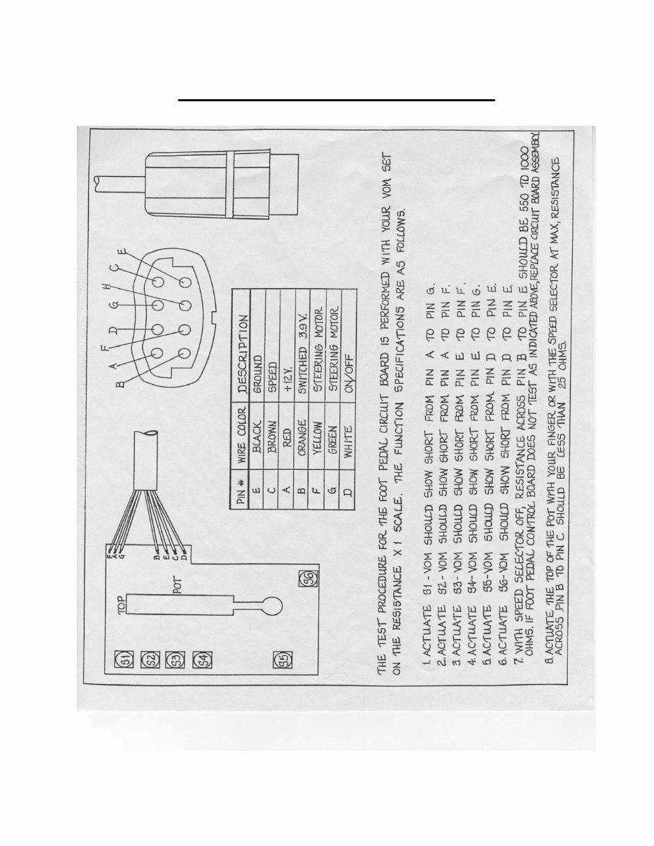
PowerDrive Repair Manual 10/31/02 3- 1 Section 3. PowerDrive (PD) Models (Corded foot pedal, non-AutoPilot & non-Genesis models) Case I. Drive Housing fails to steer left or right. Step 1. Check for proper voltage and polarity. Visually check to see that all wires are attached to proper control board terminals. Consult appropriate wiring diagram for the model and board being tested. Check for any corroded connections. Clean / rewire, if necessary. Step 2. Check motor with known good test foot pedal or test the original foot pedal by performing Foot Pedal PCB Test Procedure (see page 3-4). A. If test pedal properly steers motor or if the original pedal tests bad as outlined on page 3-4, then original foot pedal is faulty. Disassemble faulty pedal to inspect if actuators are properly making contact on foot pedal board. Visually inspect foot pedal control board for collapsed / burnt dome switches. Replace foot pedal board, if necessary. A-1. If dome switches are burnt, check drive housing for short between either of the drive housing wires and the metal portion of the drive housing itself. To do this, use a V.O.M. to check for continuity between the drive housing lead and a screw on the underside of the drive housing. A-2. If a short is found, disassemble the drive housing and insulate the wire terminals at the drive housing’s servo motor to correct the shorted condition. A-3. Reassemble the drive housing and again check for shorts. B. If test pedal does not properly steer motor or if original pedal tests okay as outlined on page 3-4, then check the drive housing. B-1. Connect 12-volt power source directly to drive housing leads. If drive housing does not steer, open drive housing. Inspect servo motor and drive gears for binding/lack of lubrication. Service drive housing to correct malfunction, as needed. If necessary, re-lubricate the bushing and sleeve contact surfaces with Schaeffer’s #238 Moly Ultra Supreme grease or a similar lubricant. Case II. Motor (lower unit) fails to run or runs intermittently. Step 1. Check for proper voltage and polarity. Visually check to see that all wires are attached to proper control board terminals. Consult appropriate wiring diagram for the model and board being tested. Check for any corroded connections. Clean / rewire, if necessary. Step 2. Check motor with known good test foot pedal or test the original foot pedal by performing Foot Pedal PCB Test Procedure (see page 3-4). A. If test pedal properly controls propeller speed or if the original pedal tested bad as outlined on page 3- 4, then original foot pedal is faulty. Disassemble faulty pedal to inspect if actuators are properly making contact on foot pedal board. Visually inspect foot pedal control board for collapsed / burnt dome switches or bad soft pot. Replace foot pedal control board, if necessary. B. If test pedal does not properly control propeller or if original pedal tests okay as outlined on page 3-4, go to Step 3. Step 3. Check to see if lower unit runs properly. A. Connect 12 volts directly to the red and black brush leads at the top of the motor shaft (in the control box). The motor should run. If not, a problem exists in the lower unit. Check the lower unit for voltage at the brushes, water in the lower unit, worn brushes, or an open or shorted armature. Repair as needed. If the motor operates properly, go to Step 4. Step 4. Check for control board output by hooking up test light (or V.O.M. probes) to board output terminals (consult appropriate wiring diagram). Use known good test pedal. Connect battery leads to proper voltage. Turn the foot pedal to CON (constant ON) and vary the speed selector. If there is no control board output, the main control board is defective. Replace main control board.
PowerDrive Repair Manual 10/31/02 3- 2 Case III. Foot pedal sticks right/left when steering. Step 1. Inspect actuators on underside of foot pedal for sand/dirt/grit. A. Disassemble and clean contaminated actuators. Replace components as required. B. Reassemble foot pedal, leave actuators dry or use a dry lubricant to avoid further contamination with sand/dirt/grit. C. NOTE: If foot pedal sticks while customer is fishing, he may simply swish the foot pedal in the water to temporarily flush the sand/dirt/grit from the actuator surfaces. Case IV. MOM/CON switch lever will not stay down in CON position. Step 1. From the underside of the footpedal, remove the 3 screws holding the slide control and switch lever in place. A. Remove screw holding the white plastic continuous actuator in place. B. Place washer (P/N 2301731) between actuator and foot pedal base. C. Reassemble slide-control and MOM/CON switch assembly. Test for proper operation. Case V. Motor won’t steer or steers slowly at higher thrust settings. NOTE: this section applies to both PowerDrive and AutoPilot models. Step 1. Inspect all battery connections, trolling motor plug (if installed), and any butt splice connections in the battery leadwire for corrosion and security. Step 2. Check to insure that wire of adequate gauge has been used in the boat’s trolling motor circuit. (Wiring of inadequate gauge will result in a voltage drop to the motor and steering circuit at higher thrust settings. See Wiring Gauge chart for recommended minimum wire sizes by amp draw and wire length, page 3-5). If, after insuring that all wiring and connections are good, the steering is still slow at high thrust settings, go to Step 3. Step 3. Disassemble motor to separate the drive housing from the motor and tube and bowplate extrusion assembly. A. Remove the six screws holding the top and bottom halves of the drive housing together. (Note: the top and bottom halves of the drive housing are “pinned” together at the corners with roll pins. The two halves will need to be pried apart.) B. Inspect the drive housing motor, paying special attention to the drive housing motor armature shaft and motor bushings. Test run to verify proper high speed operation and RPM. C. Remove the drive housing sleeve and bushings. Thoroughly clean the bushing and sleeve contact surfaces of all residue and old lubricant. Re-lubricate the bushing and sleeve contact surfaces with Schaeffer’s #238 Moly Ultra Supreme grease or a similar lubricant. Reassemble the drive housing taking special care to properly realign the drive housing pins, shafts, motor, and gears. Prior to installing and tightening the six drive housing case screws, test run the drive housing by applying 12 volts directly to the drive housing wire leads. If the drive housing motor runs properly, then make sure there are no gaps between the case halves case halves (a rubber mallet works well to seat the case halves flush/tight). Install and tighten case screws. D. Reassemble the drive housing to the bow plate/extrusion assembly. Slide the motor and tube through the drive housing. Reconnect wires in the control box. Test operation of reassembled motor to complete the repair. Case VI. Motor is loose in the cradle. Step 1. Check / replace the pivot pads (P/N 2305101), as needed. The pads tend to take a set over time. Step 2. If unit being serviced is a year 2001 or later “Grip Glide” unit, ensure the Grip Glide latch handle firmly engages the latch collar on the composite shaft. A. Loosen latch collar clamping screw. Rotate the latch collar clockwise on the shaft (when viewed from above) to screw the latch collar down towards the motor lower unit. (The collar and shaft are threaded.) B. Check to verify that the catch on the latch handle now firmly engages the latch collar. If necessary, re- adjust latch collar position. Tighten the clamping screw to hold the collar in place.
PowerDrive Repair Manual 10/31/02 3- 3 Case VII. Latch collar on shaft is broken and needs to be replaced (“Grip Glide” models manufactured for 2001 or later). Step 1. Remove any remnants of the original collar. Step 2. Remove control box cover and control box from the motor composite shaft. Loosen drive collar and slide motor lower unit and shaft out of the drive housing. Step 3. Using a large blade screwdriver as a wedge, pry open the new latch collar by inserting the blade of the screwdriver in the split of the new collar. Spread the collar open far enough to allow it to be slid down the shaft from the top to the bottom threaded section of the shaft (right above the motor lower unit). Step 4. Reassemble the motor in reverse order of disassembly. Step 5. Adjust latch collar so that the latch handle firmly engages the collar and the motor lower unit is held tightly in place on the motor rest. (See Case VI of this section for adjustment procedures.) Retighten the clamping screw on the collar.
Get instant access to the Complete Factory Service Repair Workshop Manual without any extra fees or expiry dates. This Professional Manual is suitable for your computer, tablet, or smartphone and covers all repairs, servicing, and troubleshooting procedures. It contains hundreds of pages with detailed photos and diagrams, along with step-by-step instructions and highly detailed exploded diagrams and pictures used by professional Mechanics and Technicians. You have the flexibility to print out a single page or the entire manual as per your requirement. Additionally, this is the FULL Manual without any limitations or trial periods, and it can be used for life without the need for renewal or any extra fees. It is fully compatible with all Windows and MAC Computers. Whether you are a professional mechanic or a DIY enthusiast, this manual is an essential tool for completing every job correctly.
Recently Viewed
5,521,897Happy Clients
2,594,462eManuals
1,120,453Trusted Sellers
15Years in Business
Price:
Actual Price:
MINN KOTA AUTOPILOT PD AP Models TROLLING MOTOR Full Service & Repair Manual