i M M i i n n n n K K o o t t a a S S e e r r v v i i c c e e M M a a n n u u a a l l This manual is designed to assist in basic trouble shooting procedures. Table of Contents Page Safety Warnings ii Trouble Shooting Tips iii Chapter 1. Lower Unit / Motor Assembly 1-1 (includes DC motor theory, instructions to remove motor from composite shaft, and repair information) Chapter 2. Depth Finder Interference 2-1 Chapter 3. Universal Sonar – US1 & US2 3-1 Chapter 4. Hand-Control Models with a Speed Coil 4-1 (5-speed models) Chapter 5. Hand-Control Models with a Printed Circuit Board 5-1 (Variable-speed models, non-3X) Chapter 6. Hand-Control - 3X Steering 6-1 Chapter 7. Hand-Control - Vantage 7-1 Chapter 8. Foot-Control - PowerDrive (PD) & PD V2 8-1 Chapter 9. Foot-Control - AutoPilot (PD/AP) & PD/AP V2 9-1 Chapter 10. Foot-Control - Cordless PD/C & PD/AP/C (manufactured 1996-1999) 10-1 Chapter 11. Foot-Control - Terrova 11-1 Chapter 12. Foot-Control Cable Steer Models with a Speed Coil 12-1 (5-speed Maxxum, All Terrain, & Edge models) Chapter 13. Foot-Control Cable Steer Models with a Control Board 13-1 (Variable-speed Maxxum and All Terrain models) Chapter 14. Foot-Control - Genesis (manufactured 2001-2003) 14-1 Chapter 15. PowerUp Lifts, Trims, and Tilts (manufactured 1996-2002) 15-1 Chapter 16. Engine Mount (EM) & Neptune (EP) (EP manufactured 1997-2002) 16-1 Chapter 17. DeckHand Electric Anchors 17-1 Chapter 18. CoPilot Wireless Accessory 18-1 Chapter 19. E-Drive 19-1 Chapter 20. Battery Chargers 20-1
Minn Kota Repair Manual 11/07/07 ii SAFETY WARNINGS To prevent possible eye injury, always wear SAFETY GLASSES while servicing motors. Remove propeller from motor during test procedures to eliminate chances of being cut by rotating blades. Do not run motor out of water for more than a minute at a time. The motor assemblies (and speed coils) are designed to dissipate heat through the motor shell into water. The armature seals can also dry out. Follow all battery charging precautions to eliminate chances of the escaping fumes exploding.
Minn Kota Repair Manual 11/07/07 iii Trouble Shooting Tips… With all the new features and models being added to our Minn Kota line, motor troubleshooting and repair can be quite complicated. However, with circuit board costs rising, it is more important than ever to correctly diagnose the problem before replacing parts. Here are a few trouble shooting suggestions: If possible, locate the failure before replacing any parts. Sometimes disassembly fixes the problem (pinched wires, poor connections, etc…). Look at the wiring as closely as you would the control board. There are as many problems with wires and connectors as with defective control boards. Check the coil cords on AutoPilot models. An open wire here will look like a bad board. On control boards with clear sleeves around the quick disconnects, be sure the female connector does not slip down beside the male connector. It may feel like the connector went on properly, but this connection will fail. For quick troubleshooting, use a 12-volt light bulb (automotive dome or brake light) with wires and alligator clips. Clip it to the board output and vary the speed to see if the board is working. A voltmeter on the output can sometimes be misleading. The control board needs some kind of load to work correctly. If you have replaced a board in the same motor more than once, this is probably a symptom of a larger problem. Check the wiring in the lower unit. (Shorts on the motor wires will cause board failures and shorts in PowerDrive drive housings will cause foot pedal board failures.) We still see control boards replaced under warranty that are NOT defective. To help us control costs to all our customers and to ensure that we will honor your warranty reimbursement claim, please be certain the board is defective. On AutoPilot motors, seldom do both boards fail at the same time. Please double check.
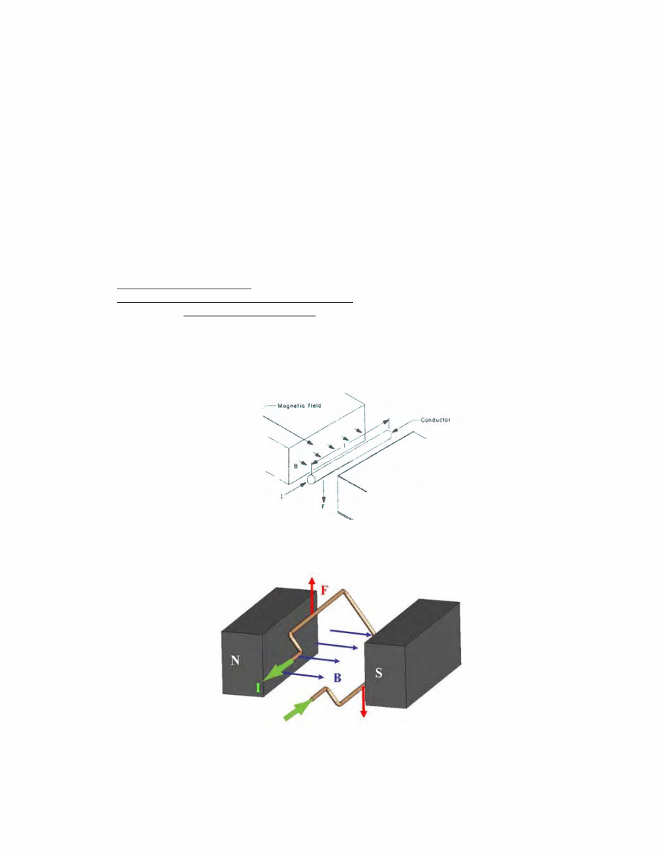
Lower Unit Repair 09/08/08 1 - 1 Chapter 1. Lower Unit / Motor Assembly This chapter refers to the motor assembly only. Like all motors, permanent magnet direct current (PM DC) motors are used to convert electrical power into mechanical power. Unlike other types of motors, permanent magnet motors convert power more efficiently. This is because a permanent magnet motor does not require electrical energy to create a magnetic field. Permanent magnets have this field already built-in, thereby reducing the consumption of electrical power by as much as 30%. A permanent magnet DC motor consists of three main parts: 1. Current carrying conductors wound around a laminated iron core called an armature (or rotor). 2. A magnetic field provided by permanent magnets (or stator). 3. Some type of sliding contact arrangement for introducing current to moving conductors (usually carbon brushes and a commutator). Understanding how an electric motor works is really quite simple, but first requires an understanding the basic principle of “electromagnetism”. This principle says simply that when current carrying conductors (“I” in the drawing below) are placed within a magnetic field (B), a force (F) will act on them. Now, imagine this single wire from the above picture is replaced with a loop of wire. Between the magnets' poles, this looks like two wires with current flowing in opposite directions. The forces on the wires cause the loop to rotate. The process of switching current direction is called commutation. To switch the direction of current, brushed DC motors use brushes and commutators. The brushes are attached to the motor's two external wires, and the commutator segments slide over the brushes so that current through the coils switches at appropriate angles.
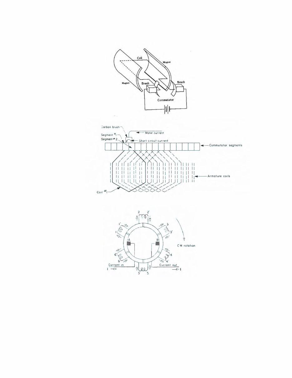
Lower Unit Repair 09/08/08 1 - 2 The following diagrams show how the brushes and commutator works together: The connection of the coils to the commutator can also be shown something like this: Current flow is in at brush A and out at brush B. The small radially-oriented arrows show current direction in the individual coil sides. If the rotation is clockwise, it can be seen that 1/6 of a revolution after the instant shown above, the current in coils 3-3’ and 6-6’ will have changed directions. As each successive commutator segments pass under the brushes, their current directions will also change. As a result of this switching, or commutation, current flow in the armature occupies a fixed position in space independent of rotation and a steady unidirectional force will result.
Lower Unit Repair 09/08/08 1 - 3 Instructions to Remove Lower Unit from Composite Shafts Step 1. Tighten the shaft and lower unit assembly in a bench vise. Utilize the Tube Holding Block Set (Minn Kota P/N 2001022) to lessen chances of scarring the shaft. The motor assembly should be slid directly next to the block set. Step 2. Heat the bung area with a commercial heat gun to loosen the LocTite. If you use a propane torch as a heat source, you risk blistering the paint. The heat needed to break down the LocTite is 450 degrees Fahrenheit for 5 minutes. We use LocTite 661 (with #7649 primer). If you cannot locate 661, 271 is more readily available and substantially less expensive. It will suffice for service work in the field. NOTE: Be careful not to heat the shaft itself (this is the reason the tube blocks should be slid down directly next to the bung when clamped in the vise). While the composite shafts are very strong, the combination of heat and the twisting force can break them. Step 3. Unscrew the lower unit from the shaft while hot. Once you break loose the LocTite, do not stop unscrewing or the LocTite may re-set. Step 4. Clean the residue out of the threads of the lower unit with the hollow tap kit (Minn Kota P/N 2881021). A. Slide the lower unit wires through the hole in the tap. B. While holding the lower unit upside down, gently screw the tap into the motor assembly letting the residue fall out. Be careful not to cross-thread the motor. Thru-bolt tightening specifications • 3 ¼” motors = 25-35 inch pounds • 3 5/8” motors = 35-45 inch pounds • 4” motors = 40-50 inch pounds • 4 5/8” motors = 40-50 inch pounds End Play specifications • Endplay should be .015” -.050”, if necessary use extra nylatron washers. Too much or too little endplay will result in motor running hot or wearing out prematurely. Case I. Lower unit does not run Step 1. Check to ensure proper voltage. Inspect all battery connections, trolling motor plug (if installed), and any butt splice connections in battery leadwire for corrosion and security. Step 2. Test lower unit directly (bypass all switches and/or control board). A. Connect the lead wire to battery. B. Hook the black battery lead directly to the black brush lead that exits the motor assembly. C. Hook the red battery lead to red brush lead that exits the motor assembly. The motor should run. If not, a problem exists in the lower unit. Disassemble lower unit and check for voltage at the brushes, water damage, brushes not making proper contact, and an open armature. C-1. An open armature will have some segments on the commutator that are dead. If the brushes happen to stop on this open segment, it will not run. If you can turn the prop a quarter and the motor starts and runs fine, the armature may have an open/dead spot. Replace armature. Case II. Motor works on high speed, but missing some or all of the lower speeds Step 1. Check speed coil functionality. A. Connect battery lead wire to battery. B. Hook the black battery lead directly to the black brush lead that exits the motor assembly. C. Touch the red battery lead to each colored speed coil wire one at a time. The motor should run as you make each connection. D. If the motor fails to run as you touch any of the colored speed coil wires, the problem is either speed coil is faulty and needs to be replaced or the speed coil jumper wire is not connected to the back of the brush plate (in the lower unit). D-1. If the motor runs as you touch the red battery lead to some of the colored speed coil wires, but not all the speed coil wires, the speed coil is faulty and needs to be replaced.
Lower Unit Repair 09/08/08 1 - 4 Case III. Motor works at all speed settings, but the customer is complaining that there is no variation between speeds. Step 1. Perform an amp draw check while the motor is running in a water test tank. A. If the amps step up as the speed setting increases, the motor is performing as designed. B. If the amp draw does not increase along with the speed settings check the amp draw of each speed directly through the speed coil: B-1. Remove the control box cover. Disconnect wires from the foot pedal (if a foot-control motor) or at the switch in the control box (if hand-control) from the wires to the lower unit. B-2. With the lower unit still in a water test tank, connect -12 volts to the black motor/brush lead. B-3. Connect +12 volts to each colored speed coil wire coming up through the motor tube from the lower unit. The motor will run (on the separate speed designations) as you make each connection. Note the amp draw as you test the different colored wires. a. If the amp draw does not vary as you make the different connections (with the lower unit still in a water test tank) replace the front end bell/potted speed coil assembly. b. If the amp draw does vary as you make the different connections, replace the 5-speed switch. Case IV. Customer complains of low power/thrust Step 1. Check to ensure proper voltage. Inspect all battery connections, trolling motor plug (if installed), and any butt splice connections in battery leadwire for corrosion and security. Step 2. Amp draw is a direct correlation to thrust. Test lower unit amp draw directly (bypass all switches and/or control board) while motor is under load in a water test tank. A. If amp draw meets specifications then the lower unit meets thrust specifications (amp specs are listed in the annual Minn Kota product brochures). A-1. Possible problem in wiring, switches, or control boards of motor or in boat’s supply voltage. A-2. Test amp draw specifications with voltage through complete trolling motor (remove any plug the consumer/dealer may have installed on the leadwire) to determine if a trolling motor problem exists or if there is a supply voltage problem to the trolling motor. B. If amp draw is lower than stated specifications: B-1. Inspect for water in lower unit. B-2. Inspect brushes and armature for discoloration or other signs of overheating (smell burnt). Replace parts as needed. B-3. Suspect low magnetism of motor shell. (Magnets lose power with time and usage.) C. If amp draw is higher than stated specifications: C-1. Check for proper/even torque of thru bolts. C-2. Check for shorted armature (commutator to armature shaft should not show continuity). C-3. The center section with magnets could be partially demagnetized causing high amp draw. Case V. Motor stops running while in use. Motor starts running again after it is pulled up out of the water and is placed back in the water, after the control box is struck, or after the prop is turned slightly. Step 1. The malfunction listed above is most likely due to an intermittent or marginal electrical connection at the armature windings and commutator. A. Dis-assemble the motor lower unit. Inspect for water damage. If water is present, repair and replace parts, as necessary. B. Inspect the armature. Examine the commutator sections for discoloration and arcing caused by the brushes as they make contact with “good/live” commutator sections and “bad/dead” sections. Test armature commutator sections for continuity from one section to the next going around the circumference of the commutator. B-1. Replace armature if severe arcing is noted or if no continuity is found when testing commutator sections. C. Examine commutator section “tangs” that connect armature windings to each commutator section. Each “tang” should be pressed down flush to the brush surface of the commutator section. If any space is noted between the “tang” and the commutator “face” the potential for an intermittent electrical connection exists and the armature needs to be replaced.
Lower Unit Repair 09/08/08 1 - 5 Case VI. Motor runs backwards Step 1. Polarity reversed to armature. Possible causes include: A. Wired backwards B. Brush plate in upside down B-1. On 4” motors the red brush lead is on the bottom; opposite on smaller motors. B-2. On 4” Terrova motors, the red brush is on the right side when viewing the brush plate from opposite the prop side. C. Magnet shell upside down (on 3 ¼” or 3 5/8” motor assemblies the marking notch should be on the bottom towards the skeg) Case VII. Motor is noisy Step 1. Possible causes: A. Water in lower unit B. Broken brush plate C. Grease or replace spherical or flange bearing D. Chipped/broken brushes (new brushes may take a few hours of operation to “seat” or round to the commutator and quiet down) E. Ensure rear seal shield (3 ¼” and 3 5/8” motors only) is securely in place and not “squealing” or rubbing against armature shaft F. Chipped/broken magnets – a rule of thumb is if the magnet that chips out is less than 1 square inch, the magnet shell is still functional. G. On 4” motors (bung on magnet center section), pull up lightly on brush wires to ensure all slack is out of lower area (so armature does not rub on the slack from the brush leads) H. Rough/worn commutator (where brushes ride) on armature. Smooth with fine sandpaper or emery cloth. If scratched too deeply, replace armature. I. Ensure the E-ring is securely snapped into place behind commutator. (Engine Mount models utilize a bushing instead of the E-ring.) J. The motors are “timed”. Before you open a lower unit it is a good idea to use a grease pencil or put a piece of tape across the joints of the lower unit (front endbell to center housing and center housingl to rear endbell). Cut the tape with razor blade. Use these marks to assemble the lower unit exactly as it was prior to disassembly. K. When re-assembling a motor assembly ensure you evenly tighten the thru-bolts. (Tighten one a little, then the other, etc... Torque specs listed on page 1-3.) Case VIII. Weedless Wedge 2 motor seems noisy Step 1. The malfunction listed above is most likely due to rough handling and concealed damage that may have occurred while the motor was in shipment to the distributor/dealer. A. Dis-assemble the motor lower unit to remove and inspect the armature thrust/support bearing (small, sealed, caged ball bearing on end of the armature shaft). B. To test for bearing smoothness/roughness grasp the outer race of the bearing and lift the armature up so that it hangs straight down below the hand grasping the bearing race and supporting the armature. With your free hand, give the armature a spin. The armature should spin freely with no feel of roughness or “catching” of the bearing. B-1. If any roughness or catching is noted inspect the armature. Examine the commutator sections for discoloration and arcing caused by the brushes as they make contact with “good/live” commutator sections and “bad/dead” sections. Replace armature if arcing is noted. B-2. Test armature commutator sections for continuity from one section to the next going around the circumference of the commutator. Replace armature if no continuity is found. B-3. Examine commutator section “tangs” that connect armature windings to each commutator section. Each “tang” should be pressed down flush to the brush surface of the commutator section. If any space is noted between the “tang” and the commutator “face” the potential for an intermittent electrical connection exists and the armature needs to be replaced. C. If the armature tested fine in Steps B-1 through B-3, then just replace the armature bearing only. A bearing puller should be used to remove the rough bearing from the armature when installing new bearing, p/n 140-010. Press or drive on inner race only when seating new bearing on shaft.
Lower Unit Repair 09/08/08 1 - 6 Case IX. Motor vibrating excessively Step 1. Possible causes include: A. Prop pin bent B. Prop – damaged or out-of-balance. Due to variables in materials, leading edge differences, and tolerance variations, some vibrations can be attributed to the prop. An easy fix is to: B-1. Disconnect leads from the battery. B-2. Remove the prop nut, keeping the prop pin horizontal. B-3. Remove the prop. B-4. Rotate the prop 180 degrees from the original position. B-5. Re-install the prop and prop nut. B-6. Re-test motor in water test tank. If vibration is not cured, replace with new propeller and re- test. If excessive vibration is still present, proceed to Step 1B. C. Armature – bent shaft or out-of-balance armature stack. C-1. Remove the prop from the armature shaft. C-2. Run the motor (never operate the motor for extended periods of time while out of water) on medium-to-high speed and watch the armature shaft for a “wobble” that may indicate a bent shaft. If wobble is noted, replace armature. You may also put your finger on the armature shaft to feel for a wobble, or briefly touch the shaft with a sharp pointed marker while it is spinning. A solid mark around the armature indicates a fairly straight shaft, while an inconsistent line may represent a bent armature shaft. Case X. Customer complains the trolling motor is draining battery / batteries down too fast Motors with a control board draw a small amount of amps whenever they are hooked to a power supply. (The relays are engaged.) Although this is a small amount, it will drain batteries down over time if the motor is left plugged in. We recommend unplugging the motor when not in use. Step 1. Perform amp draw test while motor is under load in a water test tank (amp specs are listed in the annual Minn Kota product brochures and on the top of the parts lists on the Service CD). A. If amp draw meets or is less than stated specs, the motor is not the cause of the problem. B. If amp draw is higher than stated specifications: B-1. Spin the prop by hand and feel for broken magnets. B-2. Check for proper/even torque of thru bolts. B-3. Check for shorted armature (commutator to armature shaft should not show continuity). B-4. The center section with magnets could be partially demagnetized causing high amp draw. Case XI. Motor show signs of corrosion / electrolysis Step 1. Ensure that this issue is not due to saltwater corrosion on a non-RipTide motor. A. It is a good idea to add the sacrificial anode to all motors that are used in saltwater. The anodes would replace the prop nut on the older units: p/n 2198400 for 3 ¼” and 3 5/8” motors and p/n 2198401 for 4” lower units. Step 2. If the motor is a 36-volt model, is the crank battery being used as one of the three trolling motor batteries? A. If no, go to Step 3. B. If yes, ensure the crank battery is the first battery in the trolling motor battery system. (The negative lead of the trolling motor should be connected to the crank battery.) Step 3. If the motor is a later model Universal Sonar 1 (or a US1 motor that has had an internal ground / bonding wire installed from the brush plate mounting screw to the directional indicator light circuit) ensure the ground is connected to the negative (-) side of the indicator light. A. If you are not sure which wire is the negative (-) side, power up the motor and turn it on (the light is designed to have voltage applied to it when the propeller is spinning). With your VOM (multi-meter) set to check for VDC, touch the probes to either wire on both sides of the indictor light. If you have a +12VDC reading, the negative side is the one that your black probe is touching. Step 4. The brush shunt wire may be inadvertently touching the inside of the motor case. This is more apt to happen on 4” motor assemblies after the lower unit has been opened during field repairs. Step 5. Check for shorted armature (commutator to armature shaft should not show continuity).
Depth Finder Interference 07/17/08 2 - 1 Chapter 2. Depth Finder Interference Variable speed motors with a PWM speed control / Maximizer circuit can sometimes interfere with the operation of a depth finder. This can be due to RF (radio Frequency) or electrical interference. NOTE: this procedure is for pre-Universal Sonar 2 units only. For more information regarding Universal Sonar, see Chapter 3. Here are a few steps to reduce or eliminate the interference problem: If the motor interferes with the depth finder when both are being operated: Step 1. Determine if supply voltage for trolling motor and depth finder is provided by the same / common battery. A. If yes, disconnect depth finder battery leads from the trolling motor battery and connect them to the engine cranking battery. B. Test depth finder for interference while operating motor. Step 2. Inspect for water in the lower unit. NOTE: Steps 3-5 DO NOT apply to Universal Sonar 2 units! Step 3. If interference is still present at Step 1B, proceed as follows: A. Connect a light gauge wire (18 gauge is fine) from the negative post of the trolling motor battery to the negative post of the engine’s cranking battery. We suggest installing a 1 or 2 amp inline fuse in this ground wire. (Minn Kota P/N 2060310 is the fused grounding wire.) B. Test for depth finder interference while operating the motor. Step 4. If interference is still present after installing the ground wire, proceed as follows: A. Check the routing of the depth finder and trolling motor battery leads. If they run parallel to each other for any length of distance, separate the leads as much as possible or run the leads to the trolling motor and depth finder on opposite sides of the boat. B. Test depth finder for interference while operating the motor. Step 5. The brush shunt wire may be inadvertently touching the inside of the motor case. This is more apt to happen on 4” motor assemblies, after the lower unit has been opened during field repairs. Step 6. If interference persists after completing the previous steps, proceed as follows: A. Check mounting location of the depth finder transducer. If the transducer is mounted externally on the trolling motor’s lower unit, try temporarily moving it way from the lower unit while operating the motor and observing the depth finder display. B. If the interference is reduced or eliminated when the transducer is moved away from the motor’s lower unit, the problem is due to the transducers proximity to the lower unit. C. To reduce / eliminate this type of RF interference, a ground wire can be connected to the trolling motor lower unit. This can be accomplished by means of either an external or internal connection. Grounding the motor case in this manner creates a “shield” between the motor brushes and the transducer, trapping / shunting the RFI to the ground. C-1. To ground the motor case externally, drill a small diameter hole (1/8”), in the motor skeg. Attach one end of the ground wire at this point by using a self tapping stainless steel screw (18 gauge wire may be used for this purpose). Run the ground wire up the motor shaft along with the transducer coax cable. Connect the other end of the ground wire to the motor negative battery lead or post.
Looking for detailed information about your device? Look no further than this comprehensive manual. Our manuals are available in PDF format, compatible with Windows desktop, Macs, iPad, and most PDF readers. Whether you're a professional mechanic or a DIY enthusiast, this manual serves as an ideal replacement for a missing copy and provides valuable insights into your product. Say goodbye to unreliable postal delivery – this manual is instantly accessible via download upon payment completion. With the convenience of printing only the necessary pages, you can work on your repairs without worrying about damaging the physical copy. Trust this manual to equip you with the knowledge needed to avoid unscrupulous repair services. Satisfaction guaranteed.