SPORT JET INSTALLATION Page 6A-2 90-858804 AUGUST 1998 General Information Notice to Installer Throughout this publication, “Warnings” and “Cautions” (accompanied by the International Hazard Symbol ! ) are used to alert the installer to special instructions concerning a particu- lar service or operation that may be hazardous if performed incorrectly or carelessly. –– Ob- serve Them Carefully! These “Safety Alerts,” alone, cannot eliminate the hazards that they signal. Strict com- pliance to these special instructions when performing the service, plus “common sense” op- eration, are major accident prevention measures. WARNING Hazards or unsafe practices which COULD result in severe personal injury or death. CAUTION Hazards or unsafe practices which could result in minor personal injury or product or property damage. IMPORTANT: Indicates information or instructions that are necessary for proper in- stallation and/or operation. This installation manual has been written and published by the service department of Mer- cury Marine to aid installers when installing the products described herein. It is assumed that these personnel are familiar with the installation procedures of these prod- ucts, or like or similar products manufactured and marketed by Mercury Marine. Also, that they have been trained in the recommended installation procedures of these products which includes the use of mechanics’ common hand tools and the special Mercury Marine or rec- ommended tools from other suppliers. We could not possibly know of and advise the marine trade of all conceivable procedures by which an installation might be performed and of the possible hazards and/or results of each method. We have not undertaken any such wide evaluation. Therefore, anyone who uses an installation procedure and/or tool, which is not recommended by the manufacturer, first must completely satisfy himself that neither his nor the product’s safety will be endan- gered by the installation procedure selected. All information, illustrations, and specifications contained in this manual are based on the latest product information available at time of publication. As required, revisions to this man- ual will be sent to all OEM boat companies. INSTALLATION PRODUCTS Loctite “271” 92-823089--1 Quicksilver Anti-Corrosion Grease 92-78376A6 Liquid Neoprene 92-25711--2 Dielectric Grease 92-823506--1 Perfect Seal 92-34227--1
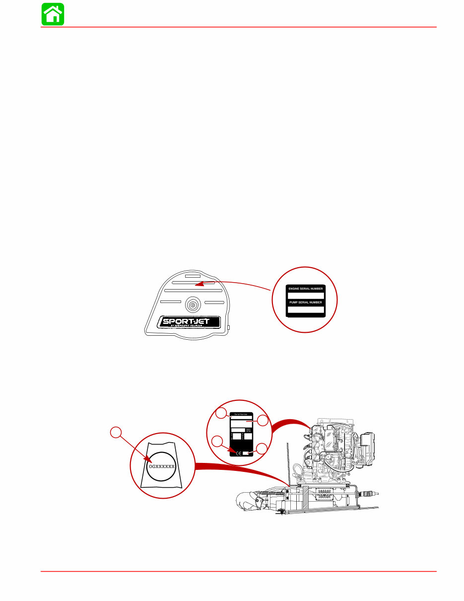
SPORT JET INSTALLATION 90-858804 AUGUST 1998 Page 6A-3 Torque Specifications NOTE: Tighten all fasteners, not listed, securely. Exhaust Bellows Clamps 50 lb. in. (5.6 N·m) Shift Cable Swivel Screws 50 lb. in. (5.6 N·m) Shift Cable Mounting Bracket Screws 50 lb. in. (5.6 N·m) 8 mm Fasteners(Powerhead to Pump) 20 lb. ft. (27 N·m) 10 mm Fasteners (Powerhead to Pump) 35 lb. ft. (47 N·m) Cooling Waterline Nut Snug with Wrench, Then Tighten One Addition Flat (60 degrees) Steering Cable Mounting Bracket Screws 200 lb. in. (23 N·m) Reverse Stop Screw 120 lb. in. (14 N·m) Forward Stop Screw 120 lb. in. (14 N·m) Ride Plate-to-Pump Screws 75 lb. in. (8.5 N·m) Drive Housing Cover to Drive Housing fasteners 35 lb. ft. (47 N·m) Serial Number Decal Location A serial number decal is located on the flywheel cover. OGXXXXXX IMPORTANT: The Pump Unit Serial Number sticker must be taken out of the envelope affixed to the pump unit and applied to the flywheel cover decal. The engine serial number and pump serial number are different and unique. The engine se- rial number is located aft of the flywheel cover. The pump unit serial number is stamped in a plug located above the shift cable hole on the port side of the pump housing. 19XX XX OGXXXXXX a b c d e a- Engine Serial Number b- Model Year c- Year Manufactured d- Certified Europe e- Pump Unit Serial Number
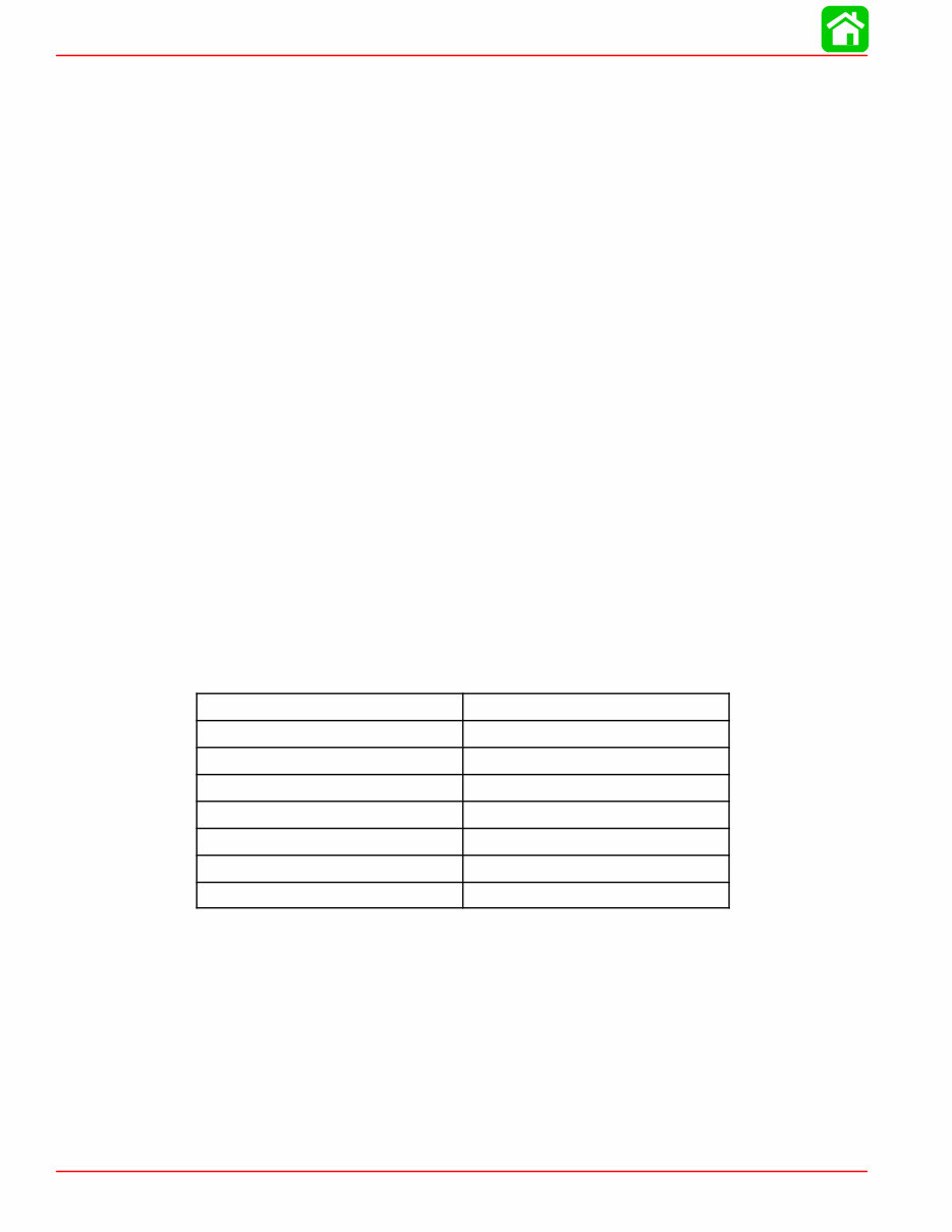
SPORT JET INSTALLATION Page 6A-4 90-858804 AUGUST 1998 Corrosion Protection This power package is equipped with anodes to help protect it from galvanic corrosion under moderate conditions. See the Operator’s Manual for location of anodes. Installation Requirements IMPORTANT: The Sport Jet is considered an INBOARD engine. The boat it is installed in must meet industry standards (ABYC, NMMA, etc.), federal standards and Coast Guard regulations for INBOARD engine installations Battery/Battery Cables IMPORTANT: Boating industry standards (ABYC, NMMA, etc.), federal standards and Coast Guard regulations must be adhered to when installing battery. Be sure battery cable installation meets the pull test requirements and that positive battery terminal is properly insulated in accordance with regulations. IMPORTANT: Engine electrical system is negative (–) ground. It is recommended (re- quired in some states) that battery be installed in an enclosed case. Refer to regula- tions for your area. 1. Select a battery that meets all of the following specifications: a. 12-volt marine type. b. 670 Marine Cranking Amps (MCA) or 520 Cold Cranking Amps (CCA). c. Reserve capacity rating of at least 100 minutes. 2. Select proper size positive (+) and negative (–) battery cables using chart. Battery should be located as close to engine as possible. IMPORTANT: Terminals must be soldered to cable ends to ensure good electrical contact. Use electrical grade (resin flux) solder only. Do not use acid flux solder, as it may cause corrosion and a subsequent failure. Cable Length Cable Gauge Up to 3-1/2 ft. (1.1 m) 4 (25 mm 2 ) 3-1/2 - 6 ft. (1.1-1.8 m) 2 (35 mm 2 ) 6 - 7-1/2 ft. (1.8-2.3 m) 1 (50 mm 2 ) 7-1/2 - 9-1/2 ft. (2.3-2.9 m) 0 (50 mm 2 ) 9-1/2 - 12 ft. (2.9-3.7 m) 00 (70 mm 2 ) 12 - 15 ft. (3.7-4.6 m) 000 (95 mm 2 ) 15 - 19 ft. (4.6-5.8 m) 0000 (120 mm 2 ) Boat Construction IMPORTANT: All applicable Coast Guard regulations for INBOARD engines must be complied with, when constructing engine compartment. Care must be exercised in the design and construction of the engine compartment. Seams must be located so that any rain water or splash, which may leak through the seams, is di- rected away from the engine and carburetor cover. Also, the passenger compartment drain- age system should not be routed directly to the engine compartment. Water that runs on or is splashed in the carburetor cover may enter the engine and cause serious dam- age to internal engine parts. IMPORTANT: Mercury Marine will not honor any warranty claim for engine damage as a result of water entry.
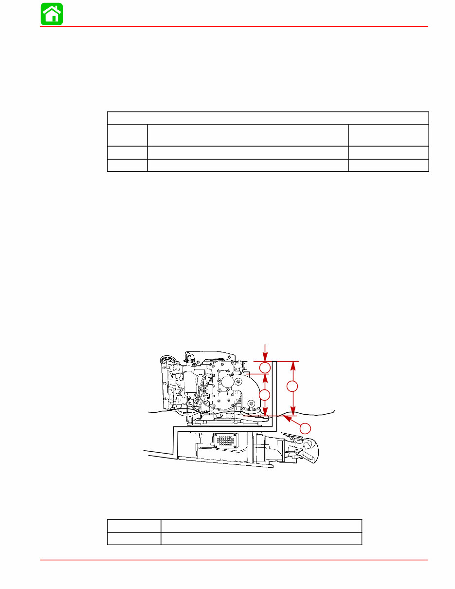
SPORT JET INSTALLATION 90-858804 AUGUST 1998 Page 6A-5 Engine Compartment Ventilation Engine compartment must be designed to provide a sufficient volume of air for engine breathing and also must vent off any fumes in engine compartment in accordance with industry standards (ABYC, NMMA, etc.), federal standards and Coast Guard regulations for inboard engines. Pressure differential (outside engine compartment versus inside engine compartment) should not exceed 2 in. (51 mm) of water (measured with a manometer) at maximum air flow rate. Engine Compartment Specifications Model Engine Air Requirements at Wide Open Throttle Physical Engine Volume* 95 HP 230 ft. 3 /min. (0.109m 3 /sec.) 0.60 ft. 3 (17 L) 120 HP 304 ft. 3 /min. (0.143 m 3 /sec.) 0.67 ft. 3 (19 L) * Physical engine volume is used in flotation calculations and is representative of the amount of flotation the engine provides. For serviceability, it is recommended that an additional 6 inches minimum (152 mm) (per side) of clearance be allowed between powerhead and engine compartment walls. Exhaust System IMPORTANT: It is the responsibility of the boat manufacturer, or installing dealer, to properly locate the engine. Improper installation may allow water to enter the exhaust manifold and combustion chambers and severely damage the engine. Damage caused by water in the engine will not be covered by Mercury Marine Limited Warranty, unless this damage is the result of defective part(s). The engine must be properly located to ensure that water will not enter the engine through the exhaust system. Determine the correct engine height by taking measurements (a) and (b), with boat at rest in the water and maximum load aboard. Subtract (b) from (a) to find (c). If (c) is less than specified in chart, boat construction must be altered to properly lower waterline relative to exhaust elbow. a b c d a- From Waterline to Top of Transom b- From Highest Point on Exhaust Elbow to Top of Transom c- (a) minus (b) = (c) d- Waterline at Rest (at Maximum Load) Model c = (a) minus (b) 95/120 HP (c) must be 7.5 in. (330 mm) or more.
Get your hands on a comprehensive service repair workshop manual that covers all repairs from A-Z for models dating back to 1998. This manual is a valuable resource for both professional mechanics and DIY enthusiasts. It includes detailed information on tools & techniques, troubleshooting, maintenance, tune-up, timing and adjustments, fuel system, electrical ignition system, jet drives/sea drives (if applicable), base repair, lower unit, tilt & trim, gear case repair, rewind starter, parts numbers, and detailed pictures and diagrams. It provides everything needed to set up, install, repair, tune, troubleshoot, and maintain your outboard.
Delivered in an easy-to-read format, this professional-quality manual is accompanied by high-quality pictures and diagrams. It is compatible with all operating systems including PC and MAC, such as Windows 95, 98, 2000, Me, Xp, Vista, and Windows 7. Whether you are using a PC or a MAC, this manual will be a valuable asset in your repair and maintenance endeavors.
Recently Viewed
5,521,897Happy Clients
2,594,462eManuals
1,120,453Trusted Sellers
15Years in Business
Price:
Actual Price:
1998 Mercury Marine 120XR Sport Jet Engine Service & Repair Manual