
")
1993-1995 Mercury 90 HP and 120 HP Sport Jet Service & Repair Manual
What's Included?
Fast Download Speeds
Online & Offline Access
Access PDF Contents & Bookmarks
Full Search Facility
Print one or all pages of your manual
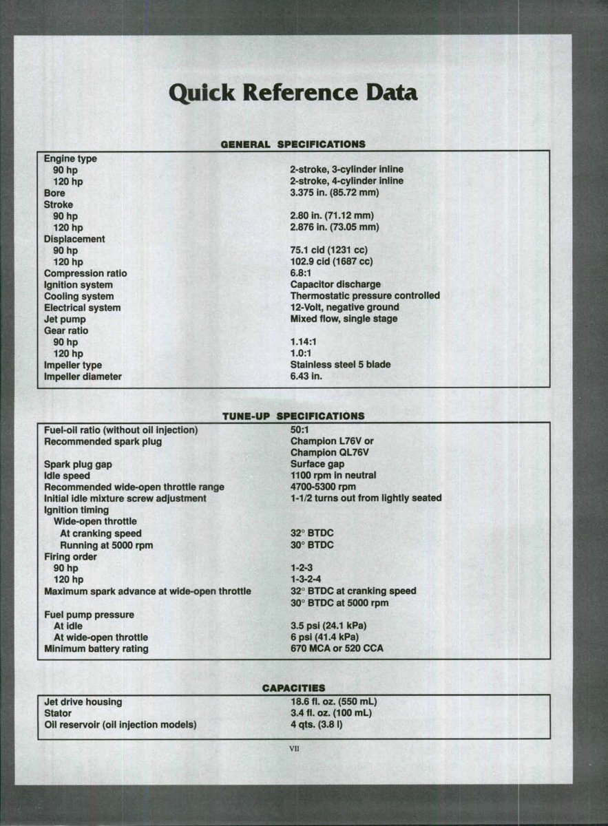
Quick Reference Data
GENERAL SPECIFICATIONS
Engine type
90 hp
120 hp
Bore
Stroke
90 hp
120 hp
Displacement
90 hp
120 hp
Compression ratio
Ignition system
Cooling system
Electricai system
Jet pump
Gear ratio
90 hp
120 hp
impeller type
impeller diameter
2-stroke, 3-cyilnder Inline
2-stroke, 4-cyilnder inline
3.375 in. (85.72 mm)
2.80 in. (71.12 mm)
2.876 in. (73.05 mm)
75.1 cid (1231 cc)
102.9 cid (1087 CO)
6.8:1
Capacitor discharge
Thermostatic pressure controlled
12-Voit, negative ground
Mixed flow, single stage
1.14:1
1.0:1
Stainless steei 5 blade
6.43 in.
TUNE-UP
Fuel-oH ratio (without oii injection)
Recommended spark plug
Spark plug gap
Idle speed
Recommended wide-open throttle range
Initiai Idle mixture screw adjustment
ignition timing
Wide-open throttle
At cranking speed
Running at 5000 rpm
Firing order
90 hp
120 hp
Maximum spark advance at wide-open throttie
Fuei pump pressure
At idie
At wide-open throttie
Minimum battery rating
SPECIFICATIONS
50:1
Champion L76V or
Champion QL76V
Surface gap
1100 rpm in neutral
4700-5300 rpm
1-1/2 turns out from lightiy seated
32° BTDC
30° BTDC
1-2-3
1-3-2-4
32° BTDC at cranking speed
30° BTDC at 5000 rpm
3.5 psi (24.1 kPa)
6psi(41.4kPa)
670 MCA or 520 CCA
CAPACITIES
Jet drive housing
Stator
OII reservoir (oii injection models)
18.6 fl.oz. (550 mL)
3.4fi.oz.(100mL)
4 qts. (3.81)
VII

Introduction
This Clymer shop manual covers the Mercury 90
and 120 hp Sport Jet propulsion system produced
from 1993-1995.
Troubleshooting, tune-up, maintenance and re-
pair are not difficult, if you know what tools and
equipment to use and how to perform the job.
Step-by-step instructions guide you through jobs
ranging from simple maintenance to complete en-
gine, drive train and steering overhaul.
This manual can be used by anyone from a first
time do-it-yourselfer to a professional mechanic.
Detailed drawings and clear photographs give you
all the information you need to do the job right.
Chapter One
General Information
Special tools are required to perform some of
the procedures in this manual. However, a re-
sourceful mechanic may be able, in come cases,
to fabricate an acceptable substitute for a particu-
lar special tool. This can be as simple as using a
few pieces of threaded rod, washers and nuts to
remove or install a bushing or bearing. However,
using a substitute for a special tool is generally
not recommended as it can cause personal injury
and may damage the part. But, if you find that a
tool can be designed, made and safely used, you
may want to search out a local community col-
lege or high school that has a machine shop
curriculum. Shop teachers sometimes welcome
outside work that can be used as practical shop
applications for advance students.
U.S. standard and metric measurements are
used throughout this manual. Table 1 contains
fractional, decimal and metric equivalents. Ta-
ble 2 lists torque specifications for general fas-
teners.
Tables 1-2 are found at the end of this chapter.
MANUAL ORGANIZATION
This chapter provides general information
useful to Sport Jet owners and mechanics. In
addition, information in this chapter discusses
the tools and techniques used for preventive
maintenance, troubleshooting and repair.
Chapter Two provides troubleshooting meth-
ods and suggestions for quick and accurate diag-
nosis and repair of problems. Troubleshooting
procedures discuss typical symptoms and logical
methods to pinpoint the trouble.
Chapter Three explains the periodic lubrica-
tion and routine maintenance necessary to keep
your Sport Jet in top operating condition. Chap-
ter Three also includes recommended tune-up
CHAPTER ONE
procedures, eliminating the need to constantly
consult other chapters on the various assemblies.
Subsequent chapters describe specific sys-
tems, providing disassembly, repair, reassembly
and adjustment procedures in simple step-by-
step form. If a specific repair procedure is im-
practical for a home mechanic, it is so indicated.
In some cases, it could even be faster and less
expensive to take such repairs to a dealer or
qualified repair shop. Specifications concerning
a specific system are located at the end of the
appropriate chapter.
NOTES, CAUTIONS AND WARNINGS
The terms NOTE, CAUTION and WARN-
ING have specific meanings in this manual. A
NOTE provides addition information to make a
step or procedure clearer or easier to understand.
Disregarding a NOTE may cause inconvenience,
but should not result in damage or personal
injury.
A CAUTION emphasizes areas where equip-
ment damage might occur. Disregarding a CAU-
TION could cause permanent mechanical
damage; however, personal injury is unlikely.
A WARNING emphasizes areas where per-
sonal injury or even death could result from
negligence. Mechanical damage may also occur.
WARNINGS are to he taken seriously. Serious
injury or death can result from disregarding
warnings.
SAFETY FIRST
Professional mechanics can work for years
and never sustain a serious injury. If you observe
a few rules of common sense and safety, you too
can enjoy many safe hours servicing your own
machine. If you ignore these rules you can hurt
yourself or damage the equipment.
1. Never use gasoline as a cleaning solvent.
2. Never smoke or use a torch in the vicinity of
flammable liquids, such as cleaning solvent, and
especially gasoline.
3. If welding or brazing is required on the ma-
chine, remove the fuel tank and move it to a safe
distance, at least 50 ft. {15m) away.
4. Use the proper size wrenches to avoid dam-
age to fasteners and injury to yourself.
5. When loosening a tight or stuck fastener, be
guided by what would happen if the wrench
should slip. Be careful and protect yourself ac-
cordingly.
6. When replacing a fastener, make sure to use
one with the same measurements and strength as
the old one. Incorrect or mismatched fasteners
can result in damage to the boat or propulsion
unit and possible personal injury. Beware of
fastener kits that are filled with cheap and poorly
made nuts, bolts, washers and cotter pins. Refer
to Fasteners in this chapter for additional infor-
mation.
7. Keep all hand and power tools in good con-
dition. Always clean greasy and oily tools after
using them. Greasy or oily tools are difficult to
hold and can cause injury. Replace or repair worn
or damaged tools.
8. Keep your work area clean and uncluttered.
9. Wear safety goggles during all operations
involving drilling, grinding, the use of a cold
GENERAL INEORMATION
chisel, punch or anytime you feel unsure about
the safety of your eyes. Safety goggles should
also be worn anytime solvent and compressed air
are used to clean parts.
10. Keep an approved fire extinguisher nearby.
Be sure it is rated for gasoline (Class B) and
electrical (Class C) fires.
11. When drying bearings or other rotating parts
with compressed air, never allow the air jet to
rotate the bearing or part. The air jet is capable
of rotating them at speeds far in excess of those
for which they were designed. The bearing or
rotating part is very likely to disintegrate causing
serious personal injury. To prevent bearing dam-
age when using compressed air, hold the inner
bearing race by hand.
SERVICE HINTS
Most of the service procedures covered are
straightforward and can be performed by anyone
reasonably skillful with tools. It is suggested,
however, that you consider your own capabilities
carefully before attempting any operation in-
volving major disassembly.
1. "FRONT" as used in this manual, refers to the
front or bow of the Sport Jet system or boat; the
front of any component is the end closest to the
front of the Sport Jet. The terms, "left-" and
"right-hand" sides refer to the position of the
propulsion system or parts as viewed when
standing behind the boat engine and jet drive
assembly. These rules are simple, but confusion
can cause a major inconvenience during service.
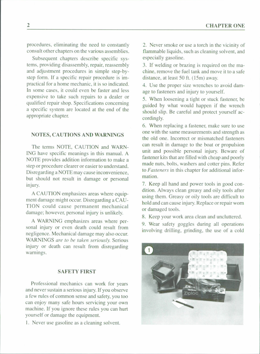
2. When disassembling any engine or drive
component, mark the parts for original location
and direction. Mark all parts which mate to-
gether, for location and direction. Small parts,
such as bolts, can be identified by placing them
in plastic sandwich bags. Seal the bags and label
them with masking tape and a marking pen (Fig-
ure 1). When reassembly will take place imme-
diately, an accepted practice is to place nuts,
screws, bolts and other fasteners in a cupcake tin
or egg carton in the order of disassembly.
3. Finished surfaces should be protected from
physical damage or corrosion. Keep gasoline
and solvent off painted surfaces.
4. Use a suitable penetrating oil on frozen or
tight bolts, then tap the bolt head a few times with
a hammer and punch (use a screwdriver on
screws). Avoid the use of heat where possible, as
it can warp, melt or affect the temper (hardness)
of the component. Heat also ruins finishes, espe-
cially paint and plastics.
5. No component removed or installed (other
than bushings and bearings) in the procedures
given in this manual should require unusual
force during disassembly or reassembly. If a part
is difficult to remove or install, find out why
before proceeding.
6. Cover all openings after removing compo-
nents or assemblies to prevent small tools, parts,
dirt or other contamination from entering.
7. Read each procedure completely while look-
ing at the actual parts before starting a job. Make
sure you thoroughly understand what is required,
then carefully follow the procedure, step-by-
step.
8. Recommendations are occasionally made to
refer service or maintenance to a Sport Jet dealer
or a specialist in a particular field. In some cases,
the work may even be done more quickly and
economically than if you performed the job
yourself.
9. In procedural steps, the term "replace" means
to discard a defective part and replace it with a
new or exchange unit. "Overhaul" means to re-
move, disassemble, inspect, measure, repair or
replace defective parts, then reassemble and in-
stall major systems or parts.
10. Some operations require the use of a hydrau-
lic or an arbor press. If a suitable press is not
available, it would be wise to have these opera-
tions performed by a shop equipped for such
work, rather than to try to do the job yourself
CHAPTER ONE
with makeshift equipment that may damage your
machine.
11. Repairs go much faster and easier if your
machine is clean before you begin work. There
are many special cleaners on the market for
washing the engine and related parts. Follow the
manufacturer's instructions on the container for
the best results. Clean all oily or greasy parts
with cleiining solvent as you remove them.
WARNING
Never use gasoline as a cleaning agent.
It presents an extreme fire hazard. Be
sure to work in a well-ventilated area
when using cleaning solvent. Keep afire
extinguisher, rated fi)r gasoline fires,
handy in any case,
12. If special tools are necessary, make arrange-
ments to obtain them before starting work. It is
frustrating and time-consuming to get partially
into a job, then be unable to complete it.
13. Make diagrams (or take a Polaroid picture)
whenever similar parts are found. For example,
crankcase bolts are often not the same length.
You may think you can remember where every-
thing came from, but mistakes can be costly. It
is also possible that you may be sidetracked and
not retum to the work for days or even weeks.
During such time carefully arranged parts may
become disturbed.
14. When reassembling parts, be sure all shims
and washers are replaced exactly as they were
removed.
15. Whenever a rotating part contacts a station-
ary part, look for a shim or washer.
16. Always install new gaskets, seals and O-
rings during reassembly. Gaskets are usually in-
stalled dry (without sealant), unless otherwise
specified.
17. If it should become necessary to make a
gasket, and the old gasket is not available for use
as a guide, use the outline of the cover or part.
Apply engine oil to the gasket surface, then place
the part on the new gasket material. Apply pres-
sure to the part and the oil will leave a very
accurate outline on the gasket material.
CAUTION
If purchasing gasket material to fabri-
cate a gasket, measure the thickness of
the old gasket. The gasket material must
have the same approximate thickness as
the original gasket.
18. Heavy grease can be used to hold small parts
in place if they tend to fall from position during
assembly. Keep grease and oil away from elec-
trical components, however. In addition, any
GENERAL INFORMATION
grease used inside the power head must be gaso-
line soluble.
19. A carburetor is best cleaned by disassem-
bling it and soaking the parts in a commercial
carburetor cleaner. Never soak gaskets and rub-
ber parts in these cleaners. Never use v^ire to
clean carburetor jets and air passages. Use com-
pressed air to blow out the carburetor passages.
20. Most of all, take your time and do the job
right. Do not forget that a newly rebuilt engine
must be correctly broken-in, just like a new one.
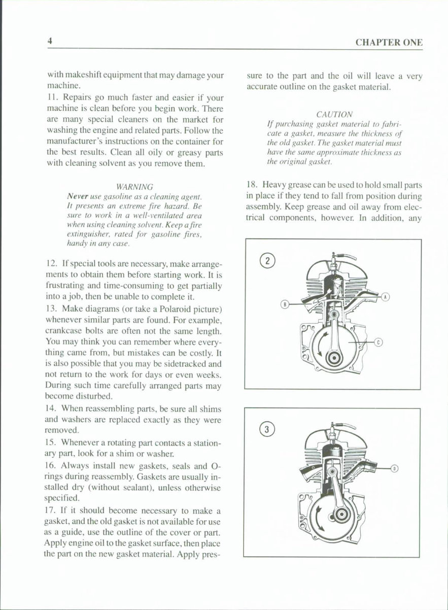
ENGINE OPERATION
All Mercury Sport Jet models are equipped
with a 2-stroke marine engine. During this dis-
cussion, assume that the crankshaft is rotating
counterclockwise in Figure 2. As the piston
travels downward, a transfer port (A, Figure 2)
between the crankcase and cylinder is uncov-
ered. The exhaust gases leave the cylinder
through the exhaust port (B, Figure 2), which is
also opened by the downward movement of the
piston. A lightly compressed, fresh fuel-air
charge travels from the crankcase (C, Figure 2)
to the cylinder through the transfer port (A) as
the port opens. Since the incoming charge is
under pressure, it rushes into the cylinder
quickly and helps to scavenge (expel) the ex-
haust gases from the previous combustion.
Figure 3 illustrates the next phase of the cycle.
As the crankshaft continues to rotate, the piston
moves upward, closing the exhaust and transfer
ports. As the piston continues upward, the air-
fuel mixture in the cylinder is compressed. No-
tice also that a vacuum is being created in the
crankcase at the same time. Further upward pis-
ton movement uncovers the intake port (D, Fig-
ure 3). A fresh fuel-air charge is then drawn into
the crankcase through the intake port because of
the vacuum created by the upward piston move-
ment.
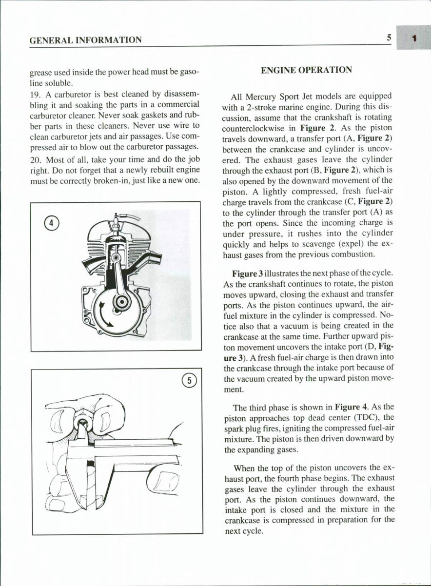
The third phase is shown in Figure 4. As the
piston approaches top dead center (TDC), the
spark plug fires, igniting the compressed fuel-air
mixture. The piston is then driven downward by
the expanding gases.
When the top of the piston uncovers the ex-
haust port, the fourth phase begins. The exhaust
gases leave the cylinder through the exhaust
port. As the piston continues downward, the
intake port is closed and the mixture in the
crankcase is compressed in preparation for the
next cycle.
CHAPTER ONE
TORQUE SPECIEICATIONS
Torque specifications throughout this manual
are given in foot-pounds (ft.-lb.) and Newton-
meters (N.m).
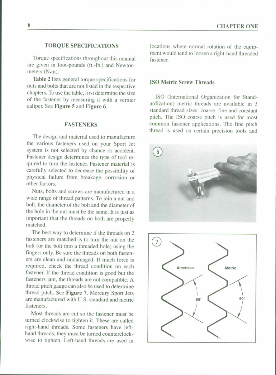
Table 2 lists general torque specifications for
nuts and bolts that are not listed in the respective
chapters. To use the table, first determine the size
of the fastener by measuring it with a vernier
caliper. See Eigure 5 and Eigure 6.
EASTENERS
The design and material used to manufacture
the various fasteners used on your Sport Jet
system is not selected by chance or accident.
Fastener design determines the type of tool re-
quired to tum the fastener. Fastener material is
carefully selected to decrease the possibility of
physical failure from breakage, corrosion or
other factors.
Nuts, bolts and screws are manufactured in a
wide range of thread patterns. To join a nut and
bolt, the diameter of the bolt and the diameter of
the hole in the nut must be the same. It is just as
important that the threads on both are properly
matched.
The best way to determine if the threads on 2
fasteners are matched is to tum the nut on the
bolt (or the bolt into a threaded hole) using the
fingers only. Be sure the threads on both fasten-
ers are clean and undamaged. If much force is
required, check the thread condition on each
fastener. If the thread condition is good but the
fasteners jam, the threads are not compatible. A
thread pitch gauge can also be used to determine
thread pitch. See Eigure 7. Mercury Sport Jets
are manufactured with U.S. standard and metric
fasteners.
Most threads are cut so the fastener must be
turned clockwise to tighten it. These are called
right-hand threads. Some fasteners have left-
hand threads; they must be turned counterclock-
wise to tighten. Left-hand threads are used in
locations where normal rotation of the equip-
ment would tend to loosen a right-hand threaded
fastener.
ISO Metric Screw Threads
ISO (International Organization for Stand-
ardization) metric threads are available in 3
standard thread sizes: coarse, fine and constant
pitch. The ISO coarse pitch is used for most
common fastener applications. The fine pitch
thread is used on certain precision tools and
GENERAL INFORMATION
instruments. The constant pitch thread is used
mainly on machine parts and is not generally
used on fasteners. The constant pitch thread is,
however, used on all metric thread spark plugs.
ISO metric threads are specified by the capital
letter M followed by the diameter in millimeters
and the pitch (or distance between each thread)
in millimeters separated by the sign "x." For
example a M8 x 1.25 bolt is one that has a
diameter of 8 millimeters with a distance of 1.25
millimeters between each thread. The measure-
ment across 2 flats on the head of the bolt indi-
cates the proper wrench size used to turn the
fastener. Figure 11 shows how to determine bolt
diameter.
NOTE
When purchasing a bolt from a dealer
or parts store, it is important to know
how to specify bolt length. The correct
way to measure bolt length is by meas-
uring the length starting from under the
bolt head to the end of the bolt. Always
measure bolt length in this manner to
avoid purchasing bolts that are too long
or too short.
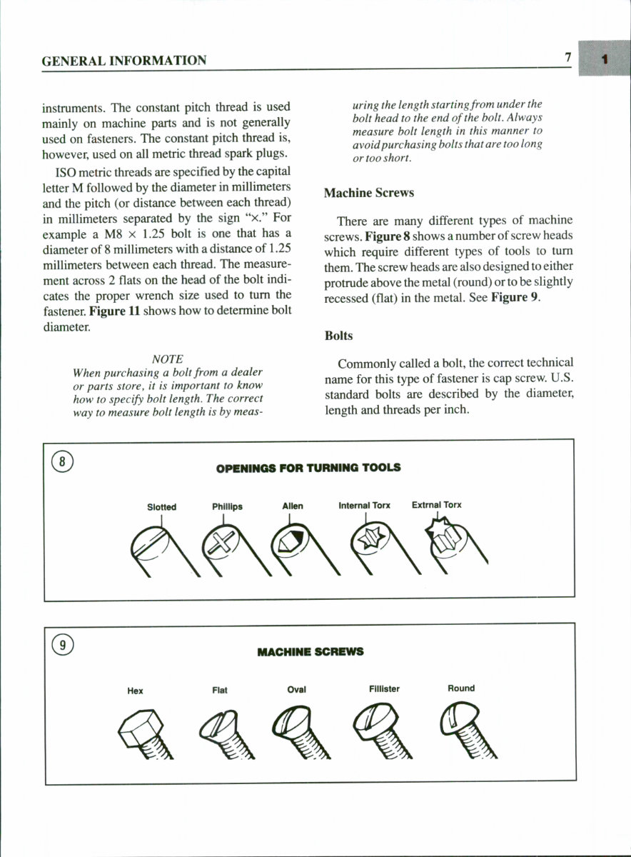
Machine Screws
There are many different types of machine
screws. Figure 8 shows a number of screw heads
which require different types of tools to turn
them. The screw heads are also designed to either
protrude above the metal (round) or to be slightly
recessed (flat) in the metal. See Figure 9.
Bolts
Commonly called a bolt, the correct technical
name for this type of fastener is cap screw. U.S.
standard bolts are described by the diameter,
length and threads per inch.
OPENINGS FOR TURNING TOOLS
Slotted Phillips
Allen Internal Tone Extrnal Torx
MACHINE SCREWS
CHAPTER ONE
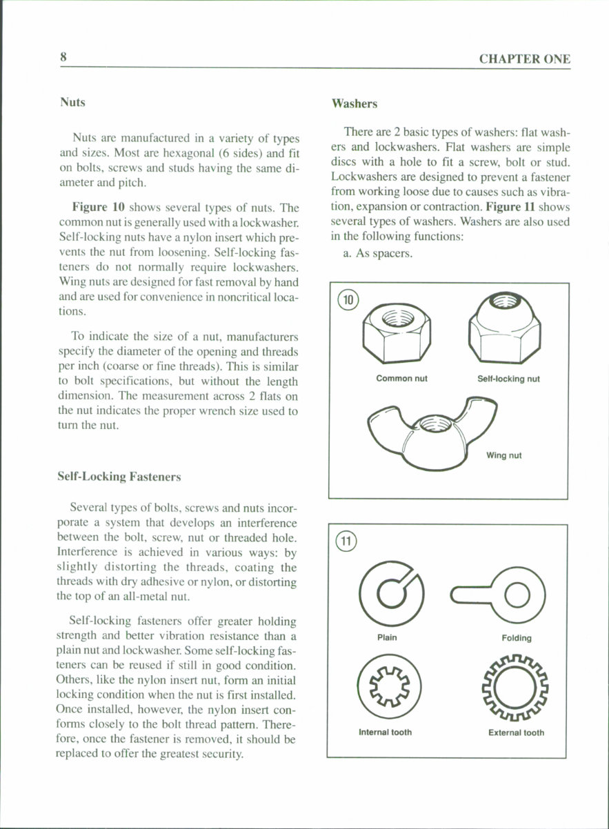
Nuts
Nuts are manufactured in a variety of types
and sizes. Most are hexagonal (6 sides) and fit
on bolts, screws and studs having the same di-
ameter and pitch.
Figure 10 shows several types of nuts. The
common nut is generally used with a lockwasher.
Self-locking nuts have a nylon insert which pre-
vents the nut from loosening. Self-locking fas-
teners do not normally require lockwashers.
Wing nuts are designed for fast removal by hand
and are used for convenience in noncritical loca-
tions.
To indicate the size of a nut, manufacturers
specify the diameter of the opening and threads
per inch (coarse or fine threads). This is similar
to bolt specifications, but without the length
dimension. The measurement across 2 flats on
the nut indicates the proper wrench size used to
tum the nut.
Self-Locking Fasteners
Several types of bolts, screws and nuts incor-
porate a system that develops an interference
between the bolt, screw, nut or threaded hole.
Interference is achieved in various ways: by
slightly distorting the threads, coating the
threads with dry adhesive or nylon, or distorting
the top of an all-metal nut.
Self-locking fasteners offer greater holding
strength and better vibration resistance than a
plain nut and lockwasher. Some self-locking fas-
teners can be reused if still in good condition.
Others, like the nylon insert nut, form an initial
locking condition when the nut is first installed.
Once installed, however, the nylon insert con-
forms closely to the bolt thread pattern. There-
fore, once the fastener is removed, it should be
replaced to offer the greatest security.
Washers
There are 2 basic types of washers: flat wash-
ers and lockwashers. Flat washers are simple
discs with a hole to fit a screw, bolt or stud.
Lockwashers are designed to prevent a fastener
from working loose due to causes such as vibra-
tion, expansion or contraction. Figure 11 shows
several types of washers. Washers are also used
in the following functions:
a. As spacers.
Common nut Self-locking nut
Wing nut
Plain Folding
Internal tooth External tooth
You're Reading a Preview
What's Included?
Fast Download Speeds
Online & Offline Access
Access PDF Contents & Bookmarks
Full Search Facility
Print one or all pages of your manual
$31.99
Viewed 17 Times Today


Secure transaction
What's Included?
Fast Download Speeds
Online & Offline Access
Access PDF Contents & Bookmarks
Full Search Facility
Print one or all pages of your manual
$31.99
This manual covers the following models:
- Mercury 90 HP Sport Jet (1993 1994 1995)
- Mercury 120 HP Sport Jet (1993 1994 1995)
Whether you are a first-time owner, amateur, or professional technician, this manual provides easy-to-read instructions and all the necessary information to perform procedures correctly. Keeping this shop manual handy and using it regularly for routine and preventive maintenance can save you time and money by preventing premature failure and unnecessary repairs.
The manual includes the following contents:
- Quick Reference Data
- Chapter One: General Information
- Manual organization
- Notes, cautions, and warnings
- Safety first
- Service hints
- Fasteners
- Lubricants
- Gasket sealant
- Threadlocking compound
- Serial numbers
- Special tools
- Mechanics tips
- Bearing replacement
- Oil Seals
- Specifications
- Chapter Two: Troubleshooting
- Operating requirements
- Starting system
- Choke circuit and solenoid test
- Key (ignition) switch test
- Charging system
- Ignition system
- Fuel system
- Power head
- Chapter Three: Lubrication, Maintenance and Tune-Up
- Lubrication
- Fuel selection
- Alcohol extended gasoline
- Oil selection
- Oil mixture
- Jet drive lubrication
- Storage
- Anticorrosion maintenance
- Engine flushing and auxiliary cooling water connection
- Tune-up
- Compression check test
- Spark plugs
- Starter solenoid check
- Wiring harness check
- Performance test
- Specifications
- Chapter Four: Engine Synchronization and Adjustment
- Engine timing and synchronization
- Carburetor linkage adjustment
- Ignition timing
- Choke valve synchronization
- Throttle and oil pump synchronization
- Specifications
- Chapter Five: Fuel System
- Fuel pump
- Carburetors
- Carburetor disassembly, reassembly, and adjustment
- Carburetor cleaning and inspection
- Core plugs and lead shot
- Reed valve assembly
- Choke solenoid
- Fuel recirculation system
- Specifications
- Chapter Six: Ignition and Electrical Systems
- Battery
- Component wiring
- Alternator charging system
- Electric starting system
- Starter motor system
- Ignition system
- Specifications
- Chapter Seven: Power Head
- Serial numbers
- Fasteners and torque specifications
- Flywheel removal/installation
- Power head disassembly
- Piston and connecting rod assembly
- Connecting rod and crankshaft
- Specifications
- Chapter Eight: Drive System
- Serial numbers
- Impeller selection
- Shift cable adjustment
- Steering cable adjustment
- Main drive housing
- Shim selection
- Jet drive pump
- Specifications
- Chapter Nine: Oil Injection System
- Oil injection
- Specifications
- Index
- Wiring Diagrams
File Format: .PDF
Compatibility: All Versions of Windows & Mac
Language: English
Requirements: Adobe Reader & WinZip


