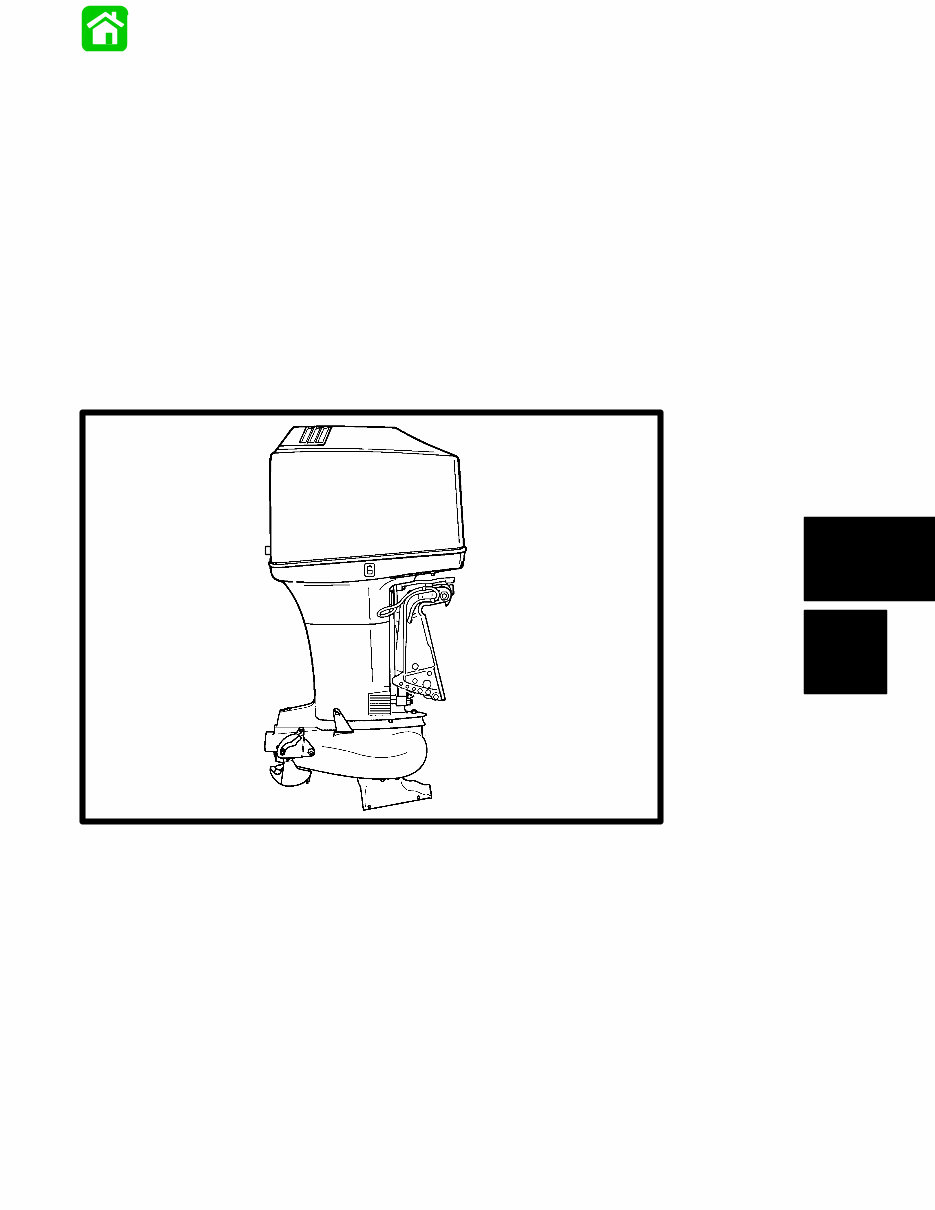
calcActive())">
1992-2000 Mercury Mariner 135HP Outboard Service & Repair Manual
What's Included?

Fast Download Speeds
Offline Viewing
Access Contents & Bookmarks
Full Search Facility
Print one or all pages of your manual

6
F
JET OUTBOARDS

6F-0 - JET OUTBOARDS 90-824052R3 JUNE 2002
Table of Contents
Page
105/140 Jet 6F-2 . . . . . . . . . . . . . . . . . . . . . . . . . . . . . .
Jet Components 6F-4 . . . . . . . . . . . . . . . . . . . . . . . . .
Selecting a Boat that is best suited for
Jet Power 6F-5 . . . . . . . . . . . . . . . . . . . . . . . . . . . . .
Engine Horsepower Selection 6F-5 . . . . . . . . . . . . . .
Transom Height of the Boat 6F-6 . . . . . . . . . . . . . . . .
Locate Centerline of the Outboard 6F-6 . . . . . . . . . .
Outboard Mounting Height 6F-6 . . . . . . . . . . . . . . . . .
Water Testing 6F-7 . . . . . . . . . . . . . . . . . . . . . . . . . . . .
Checking for Cavitation 6F-7 . . . . . . . . . . . . . . . . .
Shift Cable Installation Jet 105 and 140 6F-8 . . . . .
Lubricating the Driveshaft Bearing 6F-9 . . . . . . . . . .
Impeller Removal and Installation 6F-9 . . . . . . . . . .
Steering Pull Adjustment 6F-11 . . . . . . . . . . . . . . . . .
Impeller Clearance Adjustment 6F-11 . . . . . . . . . . . .
Worn (Dull) Impeller 6F-11 . . . . . . . . . . . . . . . . . . . . .
Flushing the Cooling System 6F-11 . . . . . . . . . . . . . .
Liner Replacement 6F-12 . . . . . . . . . . . . . . . . . . . . . .
Jet Drive Removal and Installation 6F-12 . . . . . . . . .
Bearing Carrier Disassembly 6F-14 . . . . . . . . . . . . . .
Bearing Carrier Reassembly 6F-14 . . . . . . . . . . . . . .
Installing Seals 6F-14 . . . . . . . . . . . . . . . . . . . . . . .
Installing Upper Seals 6F-15 . . . . . . . . . . . . . . . . .
Installing Driveshaft Bearing(s) 6F-15 . . . . . . . . .
Installing Driveshaft 6F-16 . . . . . . . . . . . . . . . . . . .
Installing Upper Seal Housing 6F-17 . . . . . . . . . .

90-824052R3 JUNE 2002 JET OUTBOARDS - 6F-1
Notes:

6F-2 - JET OUTBOARDS 90-824052R3 JUNE 2002
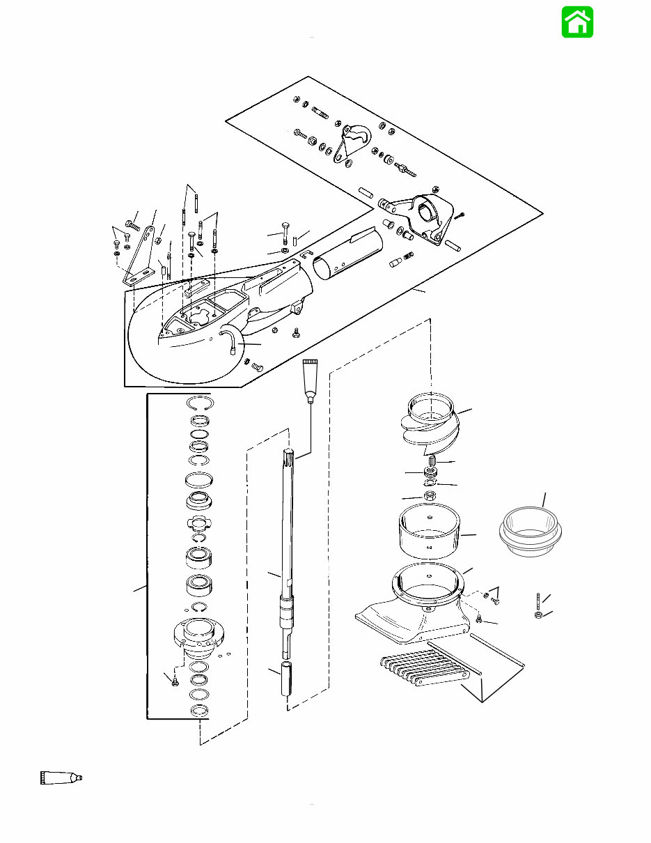
Jet Pump Assembly
1
2
3
4
6
7
8
9
10
11
12
13
14
17
18
19
20
21
22
23
24
25
26
27
7
21
95
2-4-C With Teflon (92-825407A12)
95
5
4
4
15
16

90-824052R3 JUNE 2002 JET OUTBOARDS - 6F-3
Jet Pump Assembly
REF
TORQUE
REF .
NO.
QTY. DESCRIPTION lb. in. lb. ft. N·m
– 1 JET PUMP (BLACK) S/N-0G605661 & BELOW
– 1
JET PUMP (GRAY)
– 1 JET PUMP (S/N-0G605662 & UP - W/ALUMINUM IMPELLER)
– 1 JET PUMP (JET 105 - W/STAINLESS STEEL IMPELLER)
– 1 JET PUMP (JET 140 - W/STAINLESS STEEL IMPELLER)
1
1 HOUSING–Pump (S/N-0G605662 & UP)
1
1 HOUSING–Pump (S/N-0G605661 & BELOW)
2 1 HOSE–Lube
1 IMPELLER (S/N-0G605662 & UP - ALUMINUM)
3
1 IMPELLER (JET 105 - STAINLESS STEEL)
3
1 IMPELLER (JET 140 - STAINLESS STEEL)
1 IMPELLER (S/N-0G605661 & BELOW)
4
1 HOUSING–Intake (S/N-0G605662 & UP)
4
1 HOUSING–Intake (S/N-0G605661 & BELOW)
5 1 LINER (S/N-0G605662 & UP)
6 1 LINER (S/N-0G605661 & BELOW)
7
1 SHAFT–Drive (S/N-0G605662 & UP)
7
1 SHAFT–Drive (S/N-0G605661 & BELOW)
8 1 SLEEVE
9 1 NUT Drive Tight
10 1 KEY–Impeller
11 8 SHIM
12 1 TAB WASHER
13 6
SCREW (.312-18 x 1)
(S/N-0G605661 & BELOW)
144 12 16.5
14
4 SCREW (1/4-20 x .875) 70 8.0
14
4 SCREW (.312-18 x 1) 144 12 16.5
15 6
STUD (.312-18 x 1.81)
(S/N-0G605662 & UP)
144 12 16.5
16 6 NUT 144 12 16.5
17 2 SCREW (1/4-20 x .625) 70 8.0
18 1 SCREW (.312-18 x 1.25) 160 13.5 18.0
19 1 BRACKET
20 1 NUT (.312-18) 160 13.5 18.0
21 2 PIN–Dowel
22 1 STUD (.438 x 3.12)
23 2 STUD (.44 x 2)
24 1 SCREW (.312-18 x 2-3/4)
25 2 STUD (1/4-20 x .875)
26 1 SCREW (3/8-16 x 3) 22.5 30.5
27 1 WASHER

6F-4 - JET OUTBOARDS 90-824052R3 JUNE 2002
Jet Components
1
2
3
4
5
6
7
8
9
10
11
12
13
14
15
16
17
18
19
20
21
22
23
24
21
95
95
95
2-4-C With Teflon (92-825407A12)
REF
TORQUE
REF .
NO.
QTY. DESCRIPTION lb. in. lb. ft. N·m
1 3 SCREW (.190-32 x 1.62) 30 3.5
2 3 WASHER
3 3 BUSHING
4 1 PLATE
5 1 REV LIMITER
6 1 HARNESS–Adaptor-rev limiter
7 1 GREASE KIT
8 1 WATER PUMP BASE
9 1 GASKET
10 1 OIL SEAL
11 1 OIL SEAL
12 1 GASKET–lower
13 1 GASKET–upper
14 1 FACE PLATE
15 1 WATER PUMP BODY ASSEMBLY
16 1 INSERT
17 1 SEAL–rubber
18 1 lMPELLER
19 1 KEY
20 1 SCREW (2-1/4 IN.) 50 5.5
21 2 WASHER
22 2 NUT 50 5.5
23 1 WASHER
24 1 SLEEVE

90-824052R3 JUNE 2002 JET OUTBOARDS - 6F-5
Selecting A Boat That Is
Best Suited For Jet Power
To obtain the best performance from the jet drive, the
boat should have the following features:
1. The boat should be as light as possible.
2. The boat should have hull and transom that is
designed for use with a jet drive.
3. The boat should be at least 13 feet in length.
Engine Horsepower
Selection
A boat operating at slow speed requires considerably
more depth than one which is planing on the surface
of the water. It is important therefore to use sufficient
horsepower and not to overload your boat beyond its
ability to plane. See the following table.
The following table is based on experience ob-
tained with sled-type boats using outboard jets.
The gross weights shown includes the outboard,
boat people and all the gear carried. For a given
horsepower, loading beyond these weights will
give less than satisfactory performance.
Engine Horsepower Selection
0
20
40
60
80
100
120
140
160
180
200
220
500 6 8 1000 12 14 16 2000 22 24 26 28 18 3000 32 34 36
HP
Gross Weight - Lbs.

6F-6 - JET OUTBOARDS 90-824052R3 JUNE 2002
Transom Height of the Boat
Outboards with jet drives will be mounted approxi-
mately 7 inches higher on the transom than propeller
driven outboards. This requires outboards that have
a 15 in. shaft length to be installed on boats having
a 22 in. transom height and outboards that have a 20
in. shaft length to be installed on boats having a 27
in. transom height.
If the boat transom is of insufficient height, and the
outboard cannot be installed to the recommended
height, contact the boat manufacturer for recom-
mended procedure to build up the boat transom.
Locate Centerline of the
Outboard
Locate (and mark with pencil) the vertical centerline
(a) of boat transom.
B A
D C
a
a - Centerline of Transom
Outboard Mounting Height
The initial outboard mounting height setting will work
good for most applications, however, because of
different boat/hulls designs, the setting should be
rechecked by test-running the boat. Refer to Water
Testing.
• Installing the outboard too high on the transom
will allow the water intake to suck in air and cause
cavitation (cavitation will cause the engine to
overspeed in spurts and reduce thrust). This
condition should be avoided by proper height
setting.
• Installing the outboard too low on the transom will
allow excessive drag.
SETTING OUTBOARD MOUNTING HEIGHT ON
BOATS WITH “V” BOTTOM HULLS
1. Measure the width of the leading edge on the
water intake housing. Make a horizontal line (a)
on the transom up from the “V” bottom the same
length as the width of the water intake housing
(b).
a
b
2. Place (center) the outboard on the boat transom
so that the transom brackets are resting on top of
the transom. Temporally fasten the outboard to
the transom using two C-clamps.
3. Position the outboard in a vertical position.
4. Line-up a straight edge (c) along the bottom of
the boat with the horizontal line made in Step 1
and measure the distance between the horizon-
tal line and top front edge of the water intake
housing (d).
c
d
5. Raise the outboard up on the transom the dis-
tance measured in Step 4. Use a straight edge
and recheck the mounting height. The top edge
of the water intake housing should be lined-up
with the horizontal line made in Step 1.
6. Fasten outboard to the transom at this height.

90-824052R3 JUNE 2002 JET OUTBOARDS - 6F-7
SETTING OUTBOARD MOUNTING HEIGHT ON
BOATS WITH FLAT BOTTOM HULLS
1. Place (center) the outboard on the boat transom
so that the transom brackets are resting on top of
the transom. Temporally fasten the outboard to
the transom using two C-clamps.
2. Position the outboard in a vertical position.
3. Place a straight edge (a) along the bottom of the
boat as shown and measure the distance
between the bottom of the boat and top front
edge of the water intake housing (b).
b
a
a - Straight Edge
b - Top Edge of Water Intake Housing
4. Raise the outboard up on the transom the
distance measured in Step 3. Use a straight edge
and recheck the mounting height. The top edge
of the water intake housing should be in line with
the bottom of the boat as shown.
5. Fasten outboard to the transom at this height.
Water Testing
Checking for Cavitation
Making the initial outboard height setting should be
close to the optimum setting for the outboard.
However because of the hull design of some boats,
obstructions or imperfections in the hull ahead of
the water intake may require this setting to change
in order to prevent cavitation at running speeds.
When operating the boat, the outboard driveshaft
should be vertical when planing or tilted toward the
boat in order to provide a scooping angle on the water
intake. Tilting the outboard out beyond a vertical
position reduces the scoop angle and can cause
impeller slippage and cavitation. If the angle of the
boat transom does not allow the driveshaft to be
positioned vertical a Wedge kit should be installed
behind the transom brackets to increase the tilt-in
angle.
NOTE: Slight cavitation in sharp turns and rough
water is acceptable but excessive cavitation is
harmful to the outboard and should be avoided.
Test run the boat. If cavitation occurs (air enters the
pump causing loss of thrust, engine over-speeds
erratically), the first thing to try is lowering the
outboard height 1/4 in. This can be accomplished by
elongating the drilled mounting holes in the boat
transom by 1/4 in.
If cavitation still exists after lowering the outboard 1/4
in., it maybe helpful to seek advice from the boat
manufacturer.
A number of other options are available to further
reduce cavitation.
1. Water intake fin kit (a) – Available from
Quicksilver Accessories for the Jet 20 and the
Specialty Mfg. Co. for jet models 30 thru 140. The
purpose of these fins is to ram more water into the
intake and shield the forward sides of the intake
from the entrance of air. This kit will help reduce
cavitation when running with the wind in a chop.
a
a - Intake Fin Kit
Jet 105 and 140 – Water Intake Fin Kit Part
No.1186 for jet models 105 and 140 is available
from:
Specialty Mfg. Co.
2035 Edison Ave.
San Leandro, CA 94577

6F-8 - JET OUTBOARDS 90-824052R3 JUNE 2002
Water Testing
Checking for Cavitation (Continued)
2. Rough Water Plate (b) – Using this type of plate
may be helpful in reducing cavitation when
running in windy rough water conditions where
air is sucked-in the water intake when jumping
waves. Install a 1/32 in. metal plate that extends
from the hull bottom to the top of the water intake
housing. This plate tends to reduce air intake as
well as reduce spray.
b
b - Rough Water Plate
Shift Cable Installation Jet
105 and 140
WARNING
The shift cable must be adjusted to lock the
reverse gate against unexpected engagement
(caused by water pressure hitting the gate) while
operating the boat in forward. Activation of the
reverse gate will cause sudden unexpected
stopping of the boat. Sudden stopping may
cause occupants to be thrown within the boat or
even out of the boat. This action may result in
serious injury or death.
1. Attach shift cable (a) to the shift cam (b) with flat
washer and locknut as shown. Tighten locknut
against the flat washer, then back-off the locknut
1/4 turn.
2. Place remote control handle into full forward
position.
3. Adjust the brass barrel (c) on the shift cable so
that roller (d) is at the full end of travel (bottom) in
the shift cam when the remote control is in full
forward.
4. Attach the brass barrel (c) to the bracket with bolt
and locknut. Tighten the bolt until it seats against
the barrel, then back-off the bolt 1/4 turn. Hold
bolt from turning, and tighten locknut on bolt. The
barrel must be free to pivot.
c
b
a
d
a - Shift Cable
b - Shift Cam
c - Barrel
d - Roller
5. Recheck the shift cable adjustment in forward
shift position. The correct shift adjustment will
position the cam far enough on the roller in order
to lock the the reverse gate into forward position.
You should not be able to forcibly push up the
reverse gate toward neutral. Pull on the reverse
gate by hand to verify this.
IMPORTANT: The forward locking of the reverse
gate must be met. If not, readjust the shift cable.
You're Reading a Preview
What's Included?

Fast Download Speeds
Offline Viewing
Access Contents & Bookmarks
Full Search Facility
Print one or all pages of your manual
$31.99
Viewed 41 Times Today

Loading...
Secure transaction
What's Included?

Fast Download Speeds
Offline Viewing
Access Contents & Bookmarks
Full Search Facility
Print one or all pages of your manual
$31.99
- The 1992-2000 Mercury Mariner 135HP Outboard Service & Repair Manual is a comprehensive resource for boat owners, marine mechanics, and enthusiasts servicing Mercury Mariner 135HP outboard engines manufactured between 1992 and 2000.
- This manual provides in-depth information on maintenance schedules, diagnostic procedures, and repair techniques to ensure optimal engine performance and longevity.
- It covers various aspects of service including engine overhaul, electrical systems, fuel systems, and lower unit servicing.
- Detailed illustrations and step-by-step instructions guide users through every service and repair process, ensuring tasks can be completed accurately and efficiently.
- Additionally, the manual includes essential troubleshooting guides and wiring diagrams to assist in identifying and solving engine issues quickly.
- This manual is an essential tool for maintaining the reliability and performance of Mercury Mariner 135HP outboard engines.
- Printable: Yes
- Language: English
- Compatibility: Pretty much any electronic device, incl. PC & Mac computers, Android and Apple smartphones & tablet, etc.
- Requirements: Adobe Reader (free)