

1983 Mercury 50HP 4 Cyl 2-Stroke Outboard Service & Repair Manual
What's Included?
Fast Download Speeds
Online & Offline Access
Access PDF Contents & Bookmarks
Full Search Facility
Print one or all pages of your manual
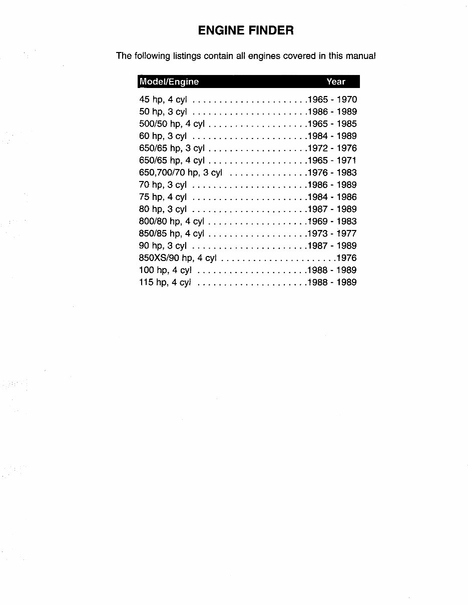
ENGINE FINDER
The following listings contain all engines covered in this manual
Model/Engine Year
45 hp, 4 cyl ...................... 1965 - 1970
50 hp, 3 cyl ...................... 1986 - 1989
500/50 hp, 4 cyl ................... 1965 - 1985
60 hp, 3 cyl ...................... 1984 - 1989
650/65 hp, 3 cyl ................... 1972 - 1976
650/65 hp, 4 cyl ................... 1965 - 1971
650,700/70 hp, 3 cyl ............... 1976 - 1983
70 hp, 3 cyl ...................... 1986 - 1989
75 hp, 4 cyl ...................... 1984 - 1986
80 hp, 3 cyl ...................... 1987 - 1989
800/80 hp, 4 cyl ................... 1969 - 1983
850/85 hp, 4 cyl ................... 1973 - 1977
90 hp, 3 cyl ...................... 1987 - 1989
850XS/90 hp, 4 cyl ...................... 1976
100 hp, 4 cyl ..................... 1988 - 1989
115 hp, 4 cyl ..................... 1988 - 1989

TABLE OF CONTENTS
1 SAFETY
INTRODUCTION 1-1
CLEANING, WAXING, & POLISHING 1-1
CONTROLLING CORROSION 1-1
PROPELLERS 1-2
FUEL SYSTEM 1-7
LOADING 1-9
HORSEPOWER 1-10
FLOTATION 1-10
EMERGENCY EQUIPMENT 1-12
COMPASS 1-14
ANCHORS 1-16
MISCELLANEOUS EQUIPMENT 1-17
BOATING ACCIDENT REPORTS 1-18
NAVIGA TION 1-18
2 TUNING
INTRODUCTION 2-1
TUNE-UP SEQUENCE 2-2
COMPRESSION CHECK 2-3
SPARK PLUG INSPECTION 2-3
IGNITION SYSTEM 2-4
TIMING AND SYNCHRONIZING 2-5
CARBURETOR ADJUSTMENT 2-7
FUEL PUMPS 2-9
CRANKING MOTOR
AND SOLENOID 2-10
INTERNAL WIRING HARNESS 2-11
WATER PUMP CHECK 2-12
PROPELLER 2-13
LOWER UNIT 2-15
BOAT TESTING 2-16
3 POWERHEAD
INTRODUCTION 3-1
Chapter Organization 3-3
POWERHEAD SERVICE -- ORIGINAL
DESIGN (See Listing on Page) 3-5
Removal 3-5
Disassembling 3-7
Cleaning & Inspecting 3-66
Assembling 3-14
Installation 3-25
POWERHEAD SERVICE -- REDESIGNED
MODEL (See Listing on Page) 3-27
Removal 3-27
Disassembling 3-32
Cleaning & Inspecting 3-66
Assembling 3-48
Installation 3-60
CLEANING & INSPECTING 3-66
Thermostat Service 3-66
Reed Block Service 3-66
Crankshaft Service 3-68
Connecting Rod Service 3-70
Piston Service 3-72
Honing Procedures 3-74
Cylinder Block Service 3-75
Check valves 3-76
4 FUEL
INTRODUCTION
GENERAL CARBURETION
INFORMA TION
TROUBLESHOOTING
"Sour" Fuel
Leaded Gasoline & Gasohol
Removing Fuel From the System
Fuel Pump Test
Fuel Line Test
Rough Engine Idle
Excessive Fuel Consumption'
Engine Surge
Anti-Syphon Valve
ENRICHENER SYSTEM
2+2 SYSTEM W/ACCELERATOR
PUMP -- 100 & 115HP
CARBURETOR IDENTIFICATION
REFERENCED "A" - SIDE BOWL
AND BACK DRAG
Removal & Disassembling
Cleaning & Inspecting
Assembling
Installation
Adjustments
4-1
4-1
4-4
4-4
4-5
4-5
4-7
4-9
4-10
4-10
4-11
4-11
4-11
4-12
4-13
4-14
4-14
4-16
4-19
4-21
4-23
4
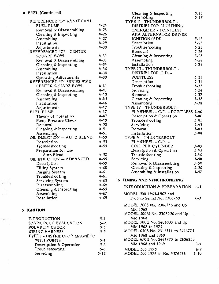
FUEL (Continued)
Cleanin~ &: Inspecting 5-14
REFERENCED "B" W/INTEGRAL
Assemb ing 5-17
TYPEII-THUNDERBOLT-
FUEL PUMP 4-24
DISTRIBUTOR LIGHTNING
Removal &: Disassembling 4-24
ENERGIZER - POINTLESS
Cleaning &: Inspecting 4-26 AKA ALTERNATOR DRIVER
Assembling 4-27 IGNITION (ADI) 5-23
Installation 4-29 Description 5-23
Adjustments 4-30 Troubleshooting 5-23
REFERENCED "C" - CENTER Removal 5-26
SQUARE BOWL 4-31 Cleaning &: Inspecting 5-28
Removal &: Disassembling 4-31 Assembling 5-28
Cleaning &: Inspecting 4-34 Installa tion 5-29
Assembling 4-36 TYPEIIT-THUNDERBOLT-
Installation 4-38 DISTRIB UTOR C.D. -
Operating Adjustments 4-39 POINTLESS 5-31
REFEREN CED "D" SERIES W ME Description 5-31
CENTER SQUARE BOWL 4-41 Troubleshooting 5-33
Removal &: Disassembling 4-41 Servicing 5-34
Cleaning &: Inspecting 4-43 Removal 5-37
Assembling 4-45 Cleaning &: Inspecting 5-38
Installation 4-46 Assembling 5-38
Adj ustm ents 4-47 TYPEIV-THUNDERBOLT-
FUEL PUMP 4-47 FL YWHEEL - C.D. - POINTLESS 5-40
Theory of Operation 4-47 Description &: Operation 5-40
Pump Pressure Check 4-49 Troubleshooting 5-41
Removal 4-50 Servicing 5-43
Cleaning &: Inspecting 4-51 Removal 5-43
Assembling 4-51 Installa tion 5-44
OIL INJECTION -- AUTO BLEND 4-53 TYPE V - THUNDERBOLT -
Description 4-53 FL YWHEEL - C.D. -
Troubleshooting 4-55 COIL PER CYLINDER 5-45
Preparation for Use Description &: Operation 5-45
Auto Blend 4-58 Troubleshooting 5-46
OIL INJECTION -- ADVANCED 4-59 Servicing 5-54
Description 4-59 Removal &: Disassembling 5-54
Filling System 4-60 Cleaning &: Inspecting 5-56
Purging System 4-61 Assembling &: Installation 5-57
Troubleshooting 4-61
Servicing System 4-63
6 nMING AND SYNCHRONIZING
Disassembling 4-64
INTRODUCTION &: PREP ARA TION 6-1
Cleaning &: Inspecting 4-65
Assembling 4-67 MODEL 500 1965-1967 and
Installation 4-69
1968 to Ser ial No. 2306755 6-3
MODEL 500S No. 2306756 and Up
5 IGNInON
Mid 1968
MODEL 500M No. 2307056 and Up
INTRODUCTION 5-1
Mid 1968
SPARK PLUG EVAUJA TION 5-2
MODEL 500E No. 2406035 and Up
POLARITY CHECK 5-4
Mid 1968 to 1975
WIRING HARNESS 5-5
MODEL 650S No. 2312311 to 2446775
TYPE I - DISTRIBUTOR MAGNETO
Mid 1968 and 1969
WITH POINTS 5-6
MODEL 650E No. 2446775 to 2606853
Description &: Operation 5-6
Mid 1968 and 1969 6-4
Troubleshooting 5-8 MODEL 500 1975 6-7
Servicing 5-12 MODEL 500 1976 to No. 4576236 6-10
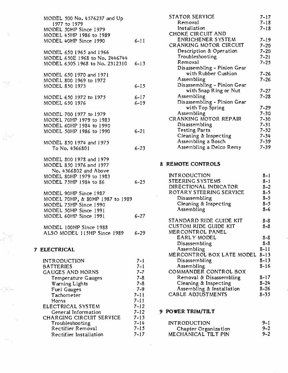
MODEL 500 No. 4576237 and Up
STA TOR SERVICE 7-17
1977 to 1979
Removal 7-18
MODEL 50HP Since 1979
Installation 7-18
MODEL 45HP 1986 to 1989
CHOKE CIRCUIT AND
MODEL 40HP Since 1990 6-11
ENRICHENER SYSTEM 7-19
CRANKING MOTOR CIRCUIT 7-20
MODEL 650 1965 and 1966
Description & Oper ation 7-20
MODEL 650E 1968 to No. 2446744
Troubleshooting 7-21
MODEL 650S 1968 to No. 2312310 6-13
Removal 7-25
Disassembling - Pinion Gear
MODEL 650 1970 and 1971
with Rubber Cushion 7-26
MODEL 800 1969 to 1972
Assembling 7-26
MODEL 850 1973 6-15
Disassembling - Pinion Gear
with Snap Ring or Nut 7-27
MODEL 650 1972 to 1975 6-17
Assembling 7-28
MODEL 650 1976 6-19
Disassembling - Pinion Gear
wi th Top Spring 7-29
MODEL 700 1977 to 1979
Assembling 7-30
MODEL 70HP 1979 to 1983
CRANKING MOTOR REPAIR 7-30
MODEL 60HP 1984 to 1990
Disassembling 7-31
MODEL 50HP 1986 to 1990 6-21
Testing Parts 7-32
Cleaning & Inspecting 7-34
MODEL 850 1974 and 1975
Assembling a Bosch 7-39
To No. 4366801 6-23
Assembling a Delco Remy 7-39
MODEL 800 1978 and 1979
MODEL 850 1976 and 1977
8 REMOTE CONTROLS
No. 4366802 and Above
MODEL 80HP 1979 to 1983
INTRODUCTION 8-1
MODEL 75HP 1984 to 86 6-25
STEERING SYSTEMS 8-1
DIRECTIONAL INDICA TOR 8-2
MODEL 90HP Since 1987
ROTAR Y STEERING SERVICE 8-5
MODEL 70HP, & 80HP 1987 to 1989
Disassembling 8-5
MODEL 75HP Since 1990
Cleaning & Inspecting 8-5
MODEL 50HP Since 1991
Assembling 8-6
MODEL 60HP Since 1991 6-27
STANDARD RIDE GUIDE KIT 8-8
MODEL 100HP Since 1988
CUSTOM RIDE GUIDE KIT 8-8
ALSO MODEL 115HP Since 1989 6-29
MERCONTROL PANEL
EARLY MODEL 8-8
Disassembling 8-8
7 ELECTRICAL
Assembling 8-11
MERCONTROL BOX LATE MODEL 8-13
INTRODUCTION 7-1 Disassembling 8-13
BATTERIES 7-1 Assembling 8-16
GA UGES AND HORNS 7-7 COMMANDER CONTROL BOX
Temperature Gauges 7-8 Removal & Disassembling 8-17
Warning Lights 7-8 Cleaning & Inspecting 8-24
Fuel Gauges 7-9
Assembling & Installation 8-26
Tachometer 7-11 CABLE ADJUSTMENTS 8-35
Horns 7-11
ELECTRICAL SYSTEM 7-12
General Information 7-12
9 POWER TRIM/TILT
CHARGING CIRCUIT SERVICE 7-13
Troubleshooting 7-14 INTRODUCTION 9-1
Rectifier Removal 7-15 Chapter Organization 9-2
Rectif ier Installation 7-17 MECHANICAL TILT PIN 9-2
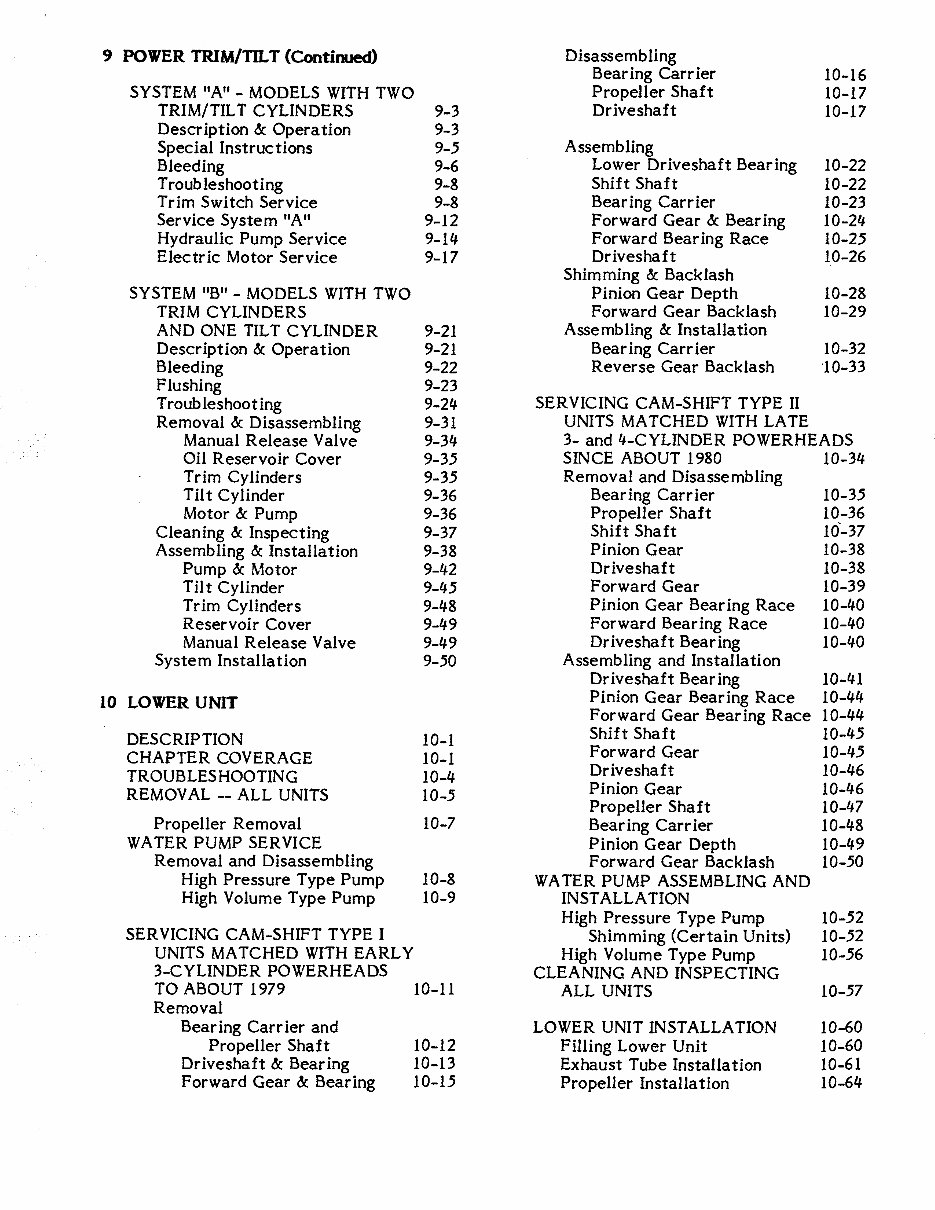
9 POWER TRIM/TILT (Continued) Disassembling
Bear ing Carr ier 10-16
SYSTEM "A" - MODELS WITH TWO Propeller Shaft 10-17
TRIM/TIL T CYLINDERS 9-3 Driveshaft 10-17
Description &: Operation 9-3
Special Instructions 9-5 Assembling
Bleeding 9-6
Lower Driveshaft Bearing 10-22
Troubleshooting 9-8 Shift Shaft 10-22
Trim Switch Service 9-8 Bearing Carrier 10-23
Service System "A" 9-12 Forward Gear &: Bearing 10-24
Hydraulic Pump Service 9-14 Forward Bearing Race 10-25
Electric Motor Service 9-17 Driveshaft 10-26
Shimming &: Backlash
SYSTEM "B" - MODELS WITH TWO Pinion Gear Depth 10-28
TRIM CYLINDERS Forward Gear Backlash 10-29
AND ONE TILT CYLINDER 9-21 Assembling &: Installation
Description &: Operation 9-21 Bear ing Carr ier 10-32
Bleeding 9-22 Reverse Gear Backlash '10-33
Flushing 9-23
Troubleshooting 9-24 SERVICING CAM-SHIFT TYPE II
Removal &: Disassembling 9-31 UNITS MATCHED WITH LATE
Manual Release Valve 9-34 3- and 4-CYLINDER POWERHEADS
Oil Reservoir Cover 9-35 SINCE ABOUT 1980 10-34
Trim Cylinders 9-35 Removal and Disassembling
Tilt Cylinder 9-36 Bearing Carr ier 10-35
Motor &: Pump 9-36 Propeller Shaft 10-36
Cleaning &: Inspecting 9-37
Shift Shaft 10'-37
Assembling &: Installation 9-38
Pinion Gear 10-38
Pump &: Motor 9-42 Driveshaft 10-38
Tilt Cylinder 9-45 Forward Gear 10-39
Trim Cylinders 9-48 Pinion Gear Bearing Race 10-40
Reservoir Cover 9-49 Forward Bearing Race 10-40
Manual Release Valve 9-49 Driveshaft Bearing 10-40
System Installation 9-50 Assembling and Installation
Driveshaft Bear ing 10-41
10 LOWER UNIT
Pinion Gear Bearing Race 10-44
Forward Gear Bearing Race 10-44
DESCRIPTION 10-1
Shift Shaft 10-45
CHAPTER COVERAGE 10-1
Forward Gear 10-45
TROUBLESHOOTING 10-4
Driveshaft 10-46
REMOV AL -- ALL UNITS 10-5
Pinion Gear 10-46
Propeller Shaft 10-47
Propeller Removal 10-7 Bear ing Carr ier 10-48
WATER PUMP SERVICE Pinion Gear Depth 10-49
Removal and Disassembling Forward Gear Backlash 10-50
High Pressure Type Pump 10-8
WATER PUMP ASSEMBLING AND
High Volume Type Pump 10-9 INSTALLA TION
High Pressure Type Pump 10-52
SERVICING CAM-SHIFT TYPE I
Shimming (Certain Units) 10-52
UNITS MATCHED WITH EARLY High Volume Type Pump 10-56
3-CYLINDER POWERHEADS
CLEANING AND INSPECTING
TO ABOUT 1979 10-11
ALL UNITS 10-57
Removal
Bear ing Carr ier and LOWER UNIT INSTALLATION 10-60
Propeller Shaft 10-12 Filling Lower Unit 10-60
Driveshaft &: Bearing 10-13 Exhaust Tube Installation 10-61
Forward Gear &: Bear ing 10-15 Propeller Installation 10-64

11 HAND REWIND STARTER
PROPELLER SERVICE
12-13
POWER TRIM/TILT
12-15
INTRODUCTION
INSIDE THE BOAT
12-16
TYPE "A" (See Introduction) 11-2
LOWER UNIT 12-16
Removal and Disassembling 11-2
WINTER STORAGE 12-18
Cleaning and Inspecting 11-4
Units With Oil Injection 12-19
Assembling and Installation 11-6
Battery Storage 12-20
Type ''S" (See Introduction)
APPENDIX
Removal and Disassembling 11-13
Cleaning and Inspecting 11-16
METRIC CONVERSION CHART A-I
Assembling and Installation 11-17
ENGINE SPECIFICATIONS
AND TUNE-UP ADJ. A-2 thru A-12
12 MAINTENANCE
REED STOP OPENING A-13
INTRODUCTION 12-1
CARBURETORJETS~E/
ELEV ATION CHART A-14
OUTBOARD SERIAL NUMBERS 12-2
LOWER UNIT BACKLASH TABLE A-16
LUBRICA TION - COMPLETE UNIT 12-2
LOWER UNIT OIL CAPACITY
PRE-SEASON PREP ARA TION 12-3
AND GEAR CHART A-17
Units With Oil Injection 12-4
PISTON & CYLINDER
All Units 12-5
SPECIFICA TIONS A-18
FIBERGLASS HULLS 12-10
WIRE IDENTIFICATION DWGS.
BELOW WATERLINE SERVICE 12-10
Igni tion Systems A-19 thru A-39
SUBMERGED ENGINE SERVICE 12-11
Power Trim/Til t A-40
Salt Water Submersion 12-11
Remote Controls A-43
Fresh Water Submersion 12-12
Console Wiring A-47
1
SAFETY
1-1 INTRODUCTION
In order to protect the investment for
the boat and outboard, they must be cared
for properly while being used and when out
of the water. Always store the boat with
the bow higher than the stern and be sure to
remove the transom drain plug and the inner
hull drain plugs. If any type of cover is used
to protect the boat, be sure to allow for
some movement of air through the hull.
Proper ventilation will assure evaporation of
any condensation that may form due to
changes in temperature and humidity.
1-2 CLEANING, WAXING, AND POLISHING
Any boat should be washed with clear
water after each use to remove surface dirt
and any salt deposits from use in salt water.
Regular rinsing will extend the time be-
tween waxing and polishing. It will also give
you "pride of ownership", by having a sharp
looking piece of equipment. Elbow grease, a
mild detergent, and a brush will be required'
to remove stubborn dirt, oil, and other un-
sightly deposits.
Stay away from harsh abrasives or strong
chemical cleaners. A white buffing com-
pound can be used to restore the or iginal
gloss to a scratched, dull, or faded area.
The finish of your boat should be thoroughly
cleaned, buffed, and polished at least once
each season. Take care when buffing or
polishing with a marine cleaner not to over-
heat the surface you are working, because
you will burn it.
1-3 CONTROLLING CORROSION
Since man first started out on the water,
corrosion on his craft has been his enemy.
The first form was merely rot in the wood
and then it was rust, followed by other
forms of destructive corrosion in the more
modern materials. One defense against cor-
rosion is to use similar metals throughout
the boat. Even though this is difficult to do
in designing a new boat, particularly the
undersides, similar metals should be used
whenever and wherever possible.
A second defense against corrosion is to
insulate dissimilar metals. This can be done
by using an exterior coating of Sea Skin or
by insulating them with plastic or rubber
gaskets.
·
········1.··.
i
l
'"
,Ij
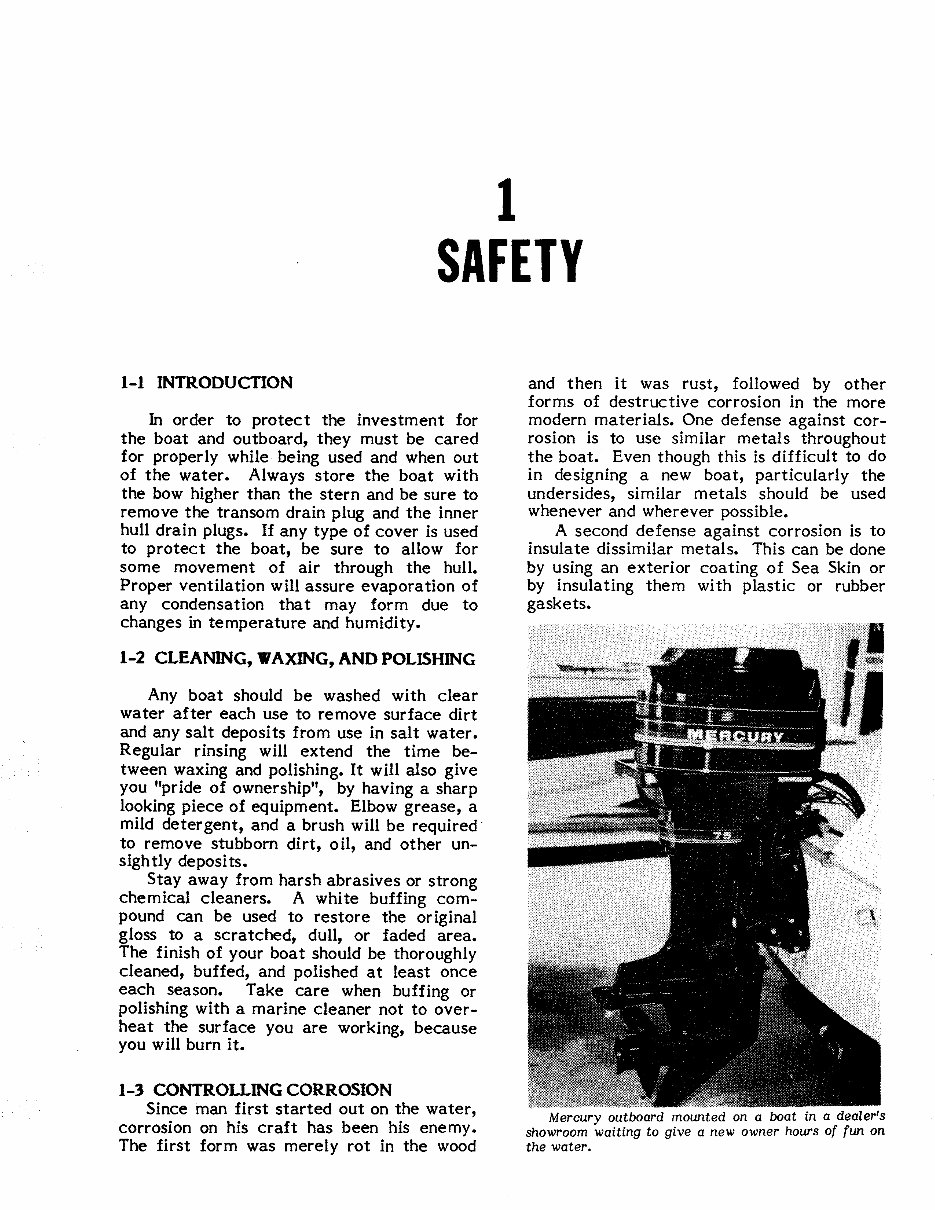
Mercury outboard mounted on a boat in a dealer's
showroom waiting to give a new owner hours of fun on
the water.
1-2 SAFETY
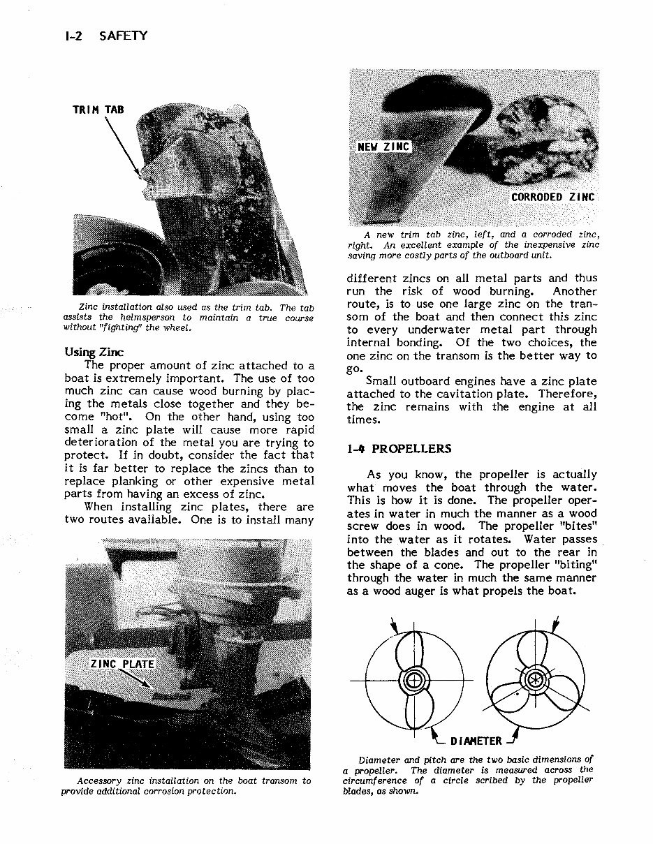
Zinc installation also used as the trim tab. The tab
assists the helmsperson to maintain a true course
without "fighting" the wheel.
Using Zinc
The proper amount of zinc attached to a
boat is extremely important. The use of too
much zinc can cause wood burning by plac-
ing the metals close together and they be-
come "hot". On the other hand, using too
small a zinc plate will cause more rapid
deterioration of the metal you are trying to
protect. If in doubt, consider the fact that
it is far better to replace the zincs than to
replace planking or other expensive metal
parts from having an excess of zinc.
When installing zinc plates, there are
two routes available. One is to install many
Accessory zinc installation on the boat transom to
provide additional corrosion protection.
A new trim tab zinc, left, and a corroded zinc,
right. An excellent example of the inexpensive zinc
saving more costly parts of the outboard unit.
different zincs on all metal parts and thus
run the risk of wood burning. Another
route, is to use one large zinc on the tran-
som of the boat and then connect this zinc
to every underwater metal part through
internal bonding. Of the two choices, the
one zinc on the transom is the better way to
go.
Small outboard engines have a zinc plate
attached to the cavitation plate. Therefore,
the zinc remains with the engine at all
times.
1... PROPELLERS
As you know, the propeller is actually
what moves the boat through the water.
This is how it is done. The propeller oper-
ates in water in much the manner as a wood
screw does in wood. The propeller "bites"
into the water as it rotates. Water passes.
between the blades and out to the rear in
the shape of a cone. The propeller "biting"
through the water in much the same manner
as a wood auger is what propels the boat.
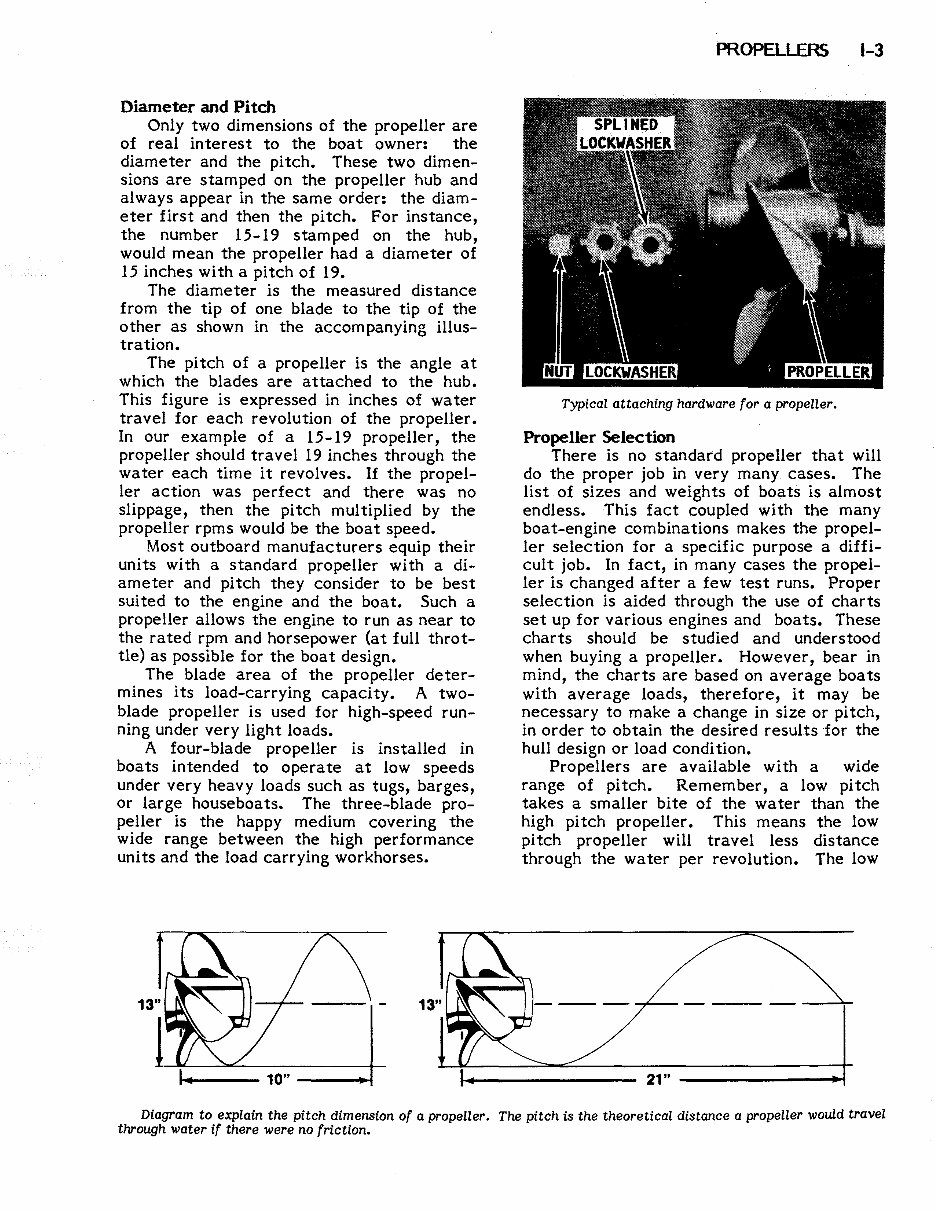
Diameter and pitch are the two basic dimensions of
a propeller. The diameter is measured across the
circumference of a circle scribed by the propeller
blades, as shown.
Diameter and Pitch
Only two dimensions of the propeller are
of real interest to the boat owner: the
diameter and the pitch. These two dimen-
sions are stamped on the propeller hub and
always appear in the same order: the diam-
eter first and then the pitch. For instance,
the number 15-19 stamped on the hub,
would mean the propeller had a diameter of
15 inches with a pitch of 19.
The diameter is the measured distance
from the tip of one blade to the tip of the
other as shown in the accompanying illus-
tration.
The pitch of a propeller is the angle at
which the blades are attached to the hub.
This figure is expressed in inches of water
travel for each revolution of the propeller.
In our exam pIe of a 15-19 propeller, the
propeller should travel 19 inches through the
water each time it revolves. If the propel-
ler action was perfect and there was no
slippage, then the pitch multiplied by the
propeller rpms would be the boat speed.
Most outboard manufacturers equip their
units with a standard propeller with a di-
ameter and pitch they consider to be best
sui ted to the engine and the boat. Such a
propeller allows the engine to run as near to
the rated rpm and horsepower (at full throt-
tle) as possible for the boat design.
The blade area of the propeller deter-
mines its load-carrying capacity. A two-
blade propeller is used for high-speed run-
ning under very light loads.
A four-blade propeller is installed in
boats intended to operate at low speeds
under very heavy loads such as tugs, barges,
or large houseboats. The three-blade pro-
peller is the happy medium covering the
wide range between the high performance
units and the load carrying workhorses.
.-.--- 10" ----t~
mOPELLERS 1-3
Typical attaching hardware for a propeller.
Propeller Selection
There is no standard propeller that will
do the proper job in very many cases. The
list of sizes and weights of boats is almost
endless. This fact coupled with the many
boat-engine combinations makes the propel-
ler selection for a specific purpose a diffi-
cult job. In fact, in many cases the propel-
ler is changed after a few test runs. Proper
selection is aided through the use of charts
set up for various engines and boats. These
charts should be studied and understood
when buying a propeller. However, bear in
mind, the charts are based on average boats
with average loads, therefore, it may be
necessary to make a change in size or pitch,
in order to obtain the desired results for the
hull design or load condition.
Propellers are available with a wide
range of pitch. Remember, a low pitch
takes a smaller bite of the water than the
high pitch propeller. This means the low
pitch propeller will travel less distance
through the water per revolution. The low
21" --------~
Diagram to explain the pitch dimension of a propeller. The pitch is the theoretical distance a propeller would travel
through water if there were no friction.
1-4 SAFETY
pitch will require less horsepower and will
allow the engine to run faster.
All engine manufacturers design their
units to operate with full throttle at, or
slightly above, the rated rpm. If you run
your engine at the rated rpm, you will
increase spark plug life, receive better fuel
economy, and obtain the best performance
from your boat and engine. Therefore, take
time to make the proper propeller selection
for the rated rpm of your engine at full
throttle with what you consider to be an
average load. Your boat will then be cor-
rectly balanced between engine and pro-
peller throughout the entire speed rahge.
A reliable tachometer must be used to
measure engine speed at full throttle to
ensure the engine will achieve full horse-
power and operate efficiently and safely.
Totes t for the correct propeller, make your
run in a body of smooth water with the
lower unit in forward gear at full throttle.
If the reading is above the manufacturer's
recommended operating range, you must try
propellers of greater pitch, until you find
the one that allows the engine to operate
continually within the recommended full
throttle range.
If the engine is unable to deliver top
performance and you feel it is properly
tuned, then the propeller may not be to
blame. Operating conditions have a marked
effect on performance. For instance, an
.')
o 0
o
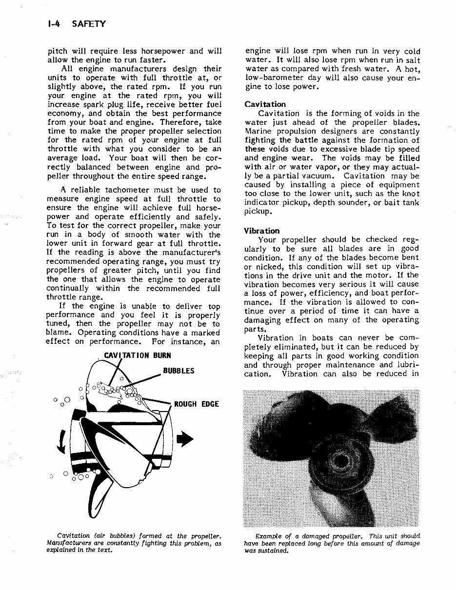
Cavitation (air bubbles) formed at the propeller.
Manufacturers are constantly fighting this problem, as
explained in the text.
engine will lose rpm when run in very cold
water. It will also lose rpm when run in salt
water as compared with fresh water. A hot,
low-barometer day will also cause your en-
gine to lose power.
Cavitation
Cavitation is the forming of voids in the
water just ahead of the propeller blades.
Marine propUlsion designers are constantly
fighting the battle against the formation of
these voids due to excessive blade tip speed
and engine wear. The voids may be filled
with air or water vapor, or they may actual-
ly be a partial vacuum. Cavitation may be
caused by installing a piece of equipment
too close to the lower unit, such as the knot
indica tor pickup, depth sounder, or bait tank
pickup.
Vibration
Your propeller should be checked reg-
ularly to be sure all blades are in good
condition. If any of the blades become bent
or nicked, this condition will set up vibra-
tions in the drive unit and the motor. If the
vibration becomes very serious it will cause
a loss of power, efficiency, and boat perfor-
mance. If the vibration is allowed to con-
tinue over a period of time it can have a
damaging effect on many of the operating
parts.
Vibra tion in boats can never be com-
pletely eliminated, but it can be reduced by
keeping all parts in good working condition
and through proper maintenance and lubri-
cation. Vibration can also be reduced in
Example of a damaged propeller. This unit should
have been replaced long before this amount of damage
was sustained.
You're Reading a Preview
What's Included?
Fast Download Speeds
Online & Offline Access
Access PDF Contents & Bookmarks
Full Search Facility
Print one or all pages of your manual
$39.99
Viewed 18 Times Today


Secure transaction
What's Included?
Fast Download Speeds
Online & Offline Access
Access PDF Contents & Bookmarks
Full Search Facility
Print one or all pages of your manual
$39.99
- Get ready to tackle outboard issues with the 1983 Mercury 50HP 4 Cyl 2-Stroke Outboard Service & Repair Manual.
- Whether you're a professional mechanic or a DIY enthusiast, this comprehensive manual offers troubleshooting and replacement procedures directly from the manufacturer.
- Equipped with step-by-step instructions, clear images, and exploded-view illustrations, this manual provides all the guidance you need for outboard repairs.
- Keep your outboard in top shape with the manufacturer's recommended troubleshooting charts and replacement procedures included in the manual.
- Save on costly repairs, enhance your outboard's reliability, and prevent future issues with this must-have resource for any outboard owner.
- Access every service and repair procedure recommended by the manufacturer, complete with step-by-step instructions, exploded-view illustrations, and clear images.
- Say goodbye to flipping through countless pages and hello to an easily accessible, searchable, and bookmarkable digital manual.
- Prefer a physical copy? You can always print it out, making it a convenient alternative to traditional bound manuals.
- Printable: Yes
- Language: English
- Compatibility: Works on various electronic devices, including PC and Mac computers, Android and Apple smartphones and tablets, and more.
- Requirements: Adobe Reader (free)


