

1996+ Mercury Mariner 40HP 4-Cylinder Outboards OEM Service & Repair Manual
You're Reading a Preview


1996+ Mercury Mariner 40HP 4-Cylinder Outboards OEM Service & Repair Manual
Models covered:
- Mercury Model 30 JET
- Mercury Model 40
Serial numbers covered:
- United States — 0C159200 and Above
- Belgium — 9570305 and Above
- Canada — 0A748269 and Above
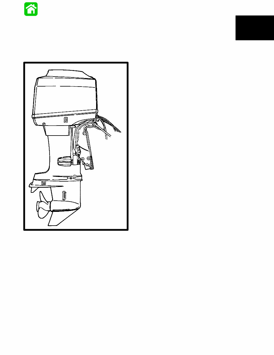
The 1996+ Mercury Mariner 40HP 4-Cylinder Outboards OEM Service & Repair Manual is the factory-issued reference used for maintaining and repairing both the 30 JET and 40HP four-cylinder outboard engines. Whether you're looking after a dependable workhorse on a fishing skiff or a family motor on a runabout, this manual keeps the maintenance process clear, consistent, and based on correct factory procedure — no guesswork, no unreliable second-hand tips.
Every major system — from carburetion to gearcase service — is broken down with step-by-step instructions, torque settings, adjustment specs, and inspection routines. This manual works equally well for professional marine technicians and DIY boat owners who want to understand their motor down to the last linkage and seal.
What’s Inside the Mercury Mariner 40HP Service & Repair Manual
Important Information
Model identification breakdown, service notes, safety practices, maintenance precautions, and setup fundamentals tailored to the 4-cylinder two-stroke platform.
Electrical & Ignition System
Ignition coil testing, timing procedures, starter motor servicing, alternator and rectifier/charging output checks, and proper synchronization of ignition components. Includes diagrams for tracing fault points and verifying signal continuity.
Fuel System & Carburetion
Carburetor cleaning and jet service, choke linkage adjustment, fuel pump inspection, tank vent troubleshooting, and mixture tuning for reliable idle and smooth throttle transition. Covers typical issues like hard starting, bogging, and surging.
Powerhead
Full teardown and rebuild instructions: cylinder head removal, piston and ring inspection, crankshaft bearings, gasket sealing, and lubrication flow paths. Also covers compression checks and wear measuring procedures for long-term engine health.
Mid-Section Assembly
Clamp bracket and swivel tube servicing, corrosion inspection points, trim and tilt mechanism operation, and servicing procedures for both manual and power trim assemblies (Design I–IV).
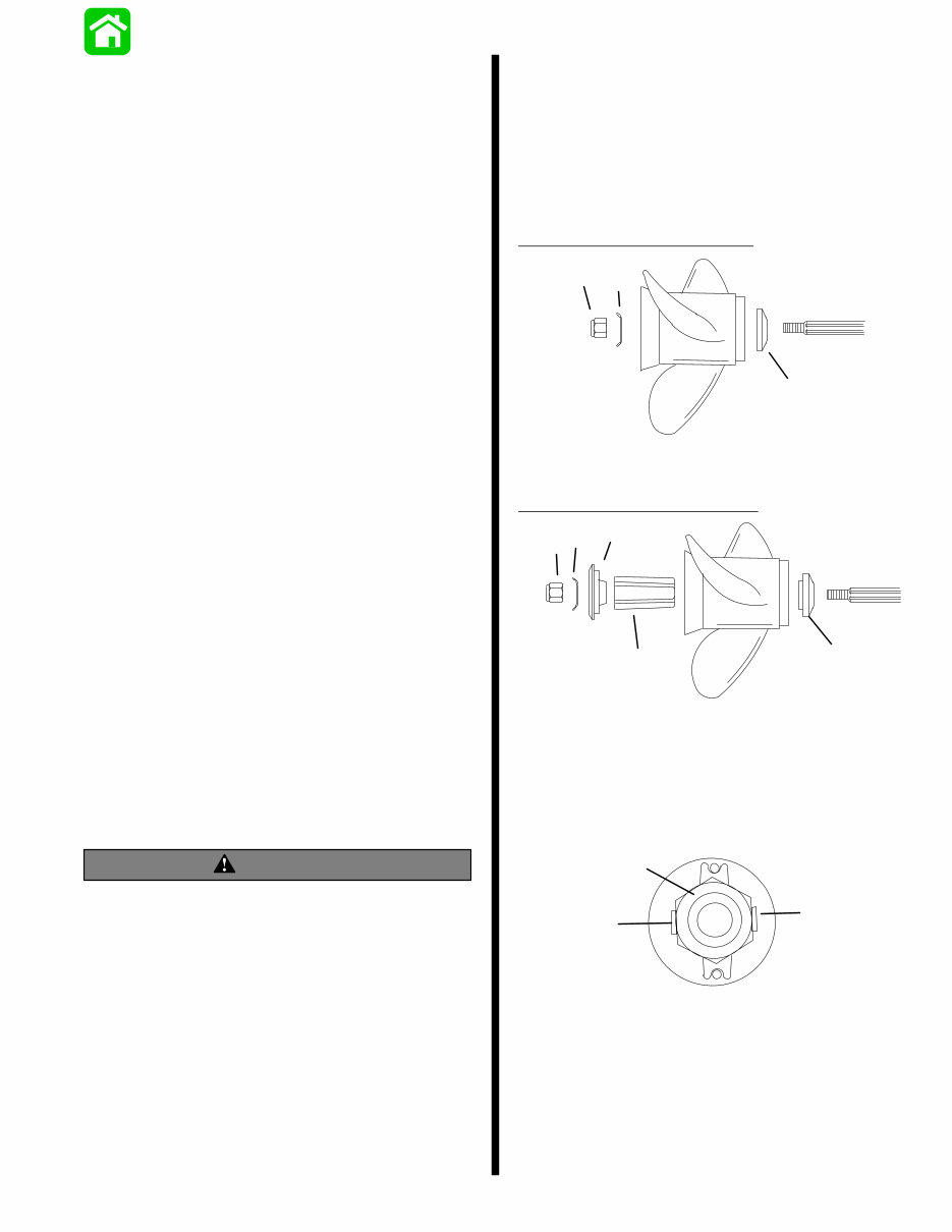
Lower Unit
Gearcase disassembly, gear and bearing inspection, driveshaft lubrication, seal replacement, impeller and water pump service, as well as configuration notes for Jet Drive units where fitted. Includes tips for diagnosing gear whine, cavitation, and cooling issues.
Outboard Motor Installation & Attachments
Proper transom mounting technique, bolt torque guidance, steering arm and tiller handle servicing, remote control integration, and rewind starter repair procedures.
Oil Injection System
Oil pump calibration procedures, reservoir bleeding, line inspection, and failure-prevention practices to avoid lubrication-related engine damage — particularly critical on engines run continuously at varying throttle loads.
Why Get the Mercury Mariner 40HP Manual?
These outboards are simple engines when you understand them, and a nightmare when you don’t. This manual makes sure you’re on the “simple” side of that equation. Whether you’re diagnosing a rough idle, replacing a water pump, or rebuilding a lower unit, this manual gives you the exact steps — no forum-guessing required.
Format & Use
Digital PDF format, fully searchable, designed for use on shop computers, laptops, tablets, or a phone tucked into a waterproof pocket. Print pages as needed — no greasy fingerprints on your original copy.
Language: English
Compatibility: Windows, macOS, Linux, iOS, Android
Requirements: PDF Reader (e.g., Adobe Reader)


