

2001 Mercury Marine Outboard Models Factory Service & Work Shop Manual
What's Included?
Fast Download Speeds
Online & Offline Access
Access PDF Contents & Bookmarks
Full Search Facility
Print one or all pages of your manual

CONTENTS
HOW TO USE THIS MANUAL 1·2
BOATING SAFETY 1-4
BOATING EQUIPME~ ( NOT REQUIRED
BUT RECOMMENDED) 1010
SAFffi IN SERVICE 1·12
TROUBLESHOOTING , ·1 3
SHOP EQUIPMENT '·17
TOOLS 1-19
fASTENERS, MEASUREMENT , AND CONVERSIONS 1-27
SPECIFICATIONS '·28
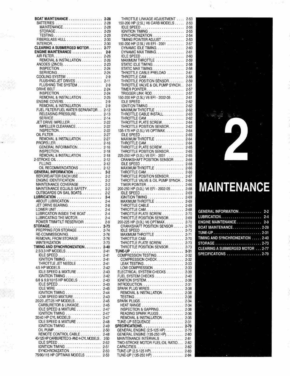
GENERAL INFORMATION 2·2
LUBRICATION 2-4
ENGINE MAINTENANCE 2·9
BOAT MAINTENANCE 2·28
TUNE-UP 2-31
TIMING AND SYNCHRONIZATION 2-40
STORAGE 2·73
CLEARING A SUBMERGED MOTOR 2·n
SPECIFICATIONS 2·79
FUEL AND COMBUSTION BASICS 3-2
FUEL TANK AND LINES 3·7
CARBURETED FUEL SYSTEM 3·12
ELECTRONIC FUEL INJECTION 3-44
OPTIMAX DIRECT FtlEl l NJECTJON ( OFI) 3-73
SPECIFICATIONS 3-107
UNDERSTANDING AND TAOUBLESHOOTING
ELECTRICAL SYSTEMS 4-2
IGNITION SYSTEMS 4-8
CHARGING CIRCUIT 4-40
SPECIFICATIONS 4-43
ELECTRICAL SWITCHISOLENOIO SERVICE 4-64
WIAING DIAGRAMS 4-66
OIL I NJECTION SYSTEM 5-2
COOLING SYSTEM 5-11
WARNING SYSTEMS 5-31
COOLING SYSTEM FLOW SCHEMATICS 5-41
SPECIFICATIONS S-46
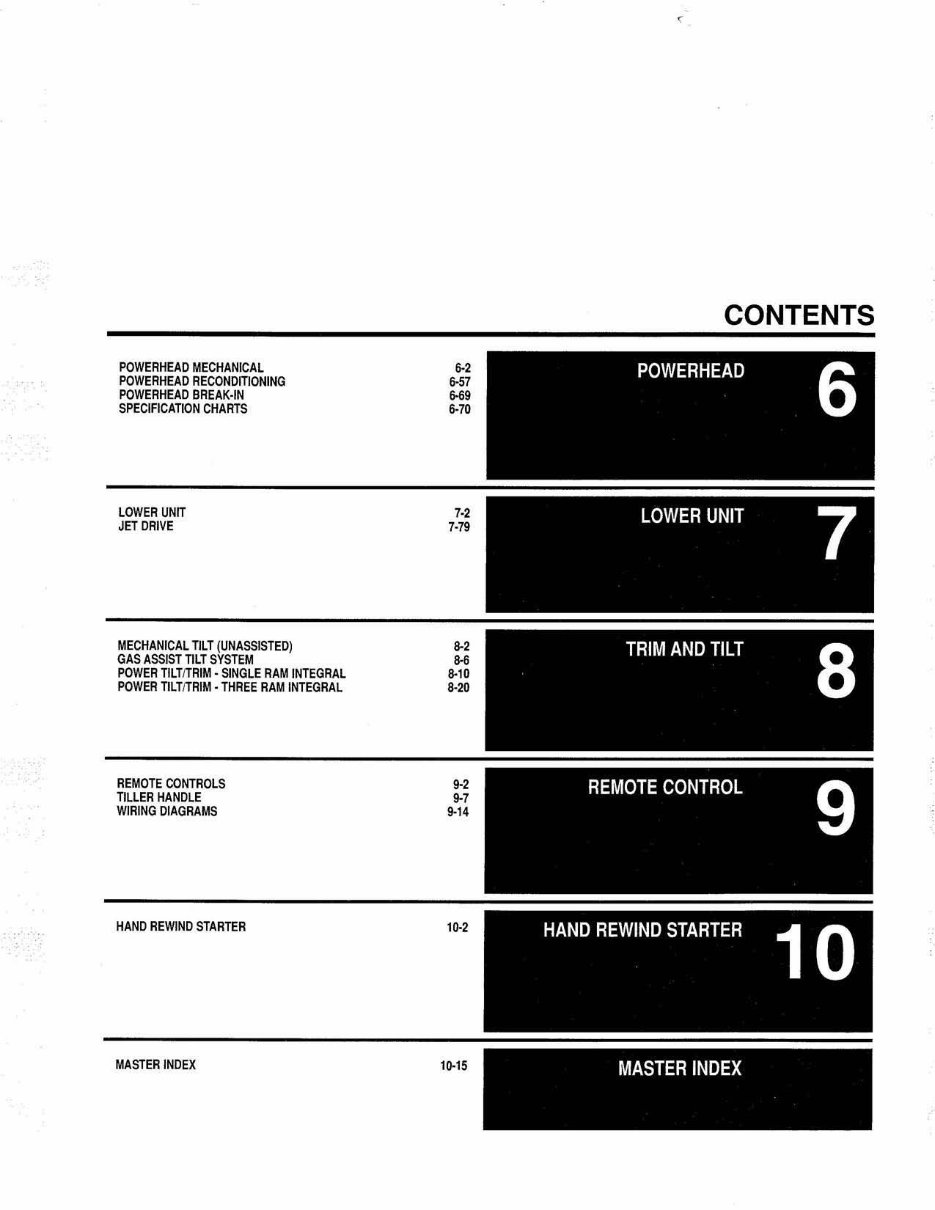
POWERHEAD MECHANICAL
POWERHEAD RECONDITIONING
POWERHEAO BREAK-IN
SPECIFICATION CHARTS
LOWER UNIT
JET DRIVE
MECHANICAL TILT (UNASSISTED)
GAS ASSIST nlT SYSTEM
POWER TllTfTRIM - SINGLE RAM INTEGRAL
POWER nLT/1RIM· THREE RAM INTEGRAL
REMOTE CONTROLS
nllER HANDLE
WIRING DIAGRAMS
HAND ReWIND STARTER
MASTER INDEX
6-2
6-57
.. 9
6-70
7-2
7-79
8-2
..
8-10
8-2<1
9-2
9-7
9-14
1~2
1!H5
<
CONTENTS
MASTER INDEX
BOAT MAINTENANCE .. . . . •• . . ••• . . •••. 2·28
BATIERI ES . . . . . . . . . . 2·28
MAINTENANCE. 2·28
STORAGE. . . . 2·29
TESTING. . . .. . . . .. . . . .• 2·29
FI BERGlASS HULL. 2·30
INTERIOR ... .. ... . ..... .. .. . .... .. .. 2-30
CLEARING A SUBMERGED MOT OR •••..•• 2·77
ENGINE MAINTENANCE .. .• . •• . . . •• . . •• 2·9
AIR FILTER .. ...... .. . .. .. .. 2·26
REMOVAL & INSTALLATION . 2·26
ANODES ( ZINCS). . . . 2·23
INSPECTION. . . . . . . . . . . . . 2·24
SERVICING . . . . . . . . . . .. 2·24
COOLING SYSTEM . • . 2·9
FLUSHI NG JET DRIVES .. . .. . .. .. ... 2 ·11
FLUSHING THE SYSTEM . 2·9
DRIVE BELT. . . . . . . .. . . . 2·24
INSPECTION. . . . . . . . . . . . . •. 2·24
REMOVAL & IN STAL LATION .. . ........ 2·25
ENGINE COVERS. . . . . .. . . . . 2·9
REMOVAL & I NSTALLATION . . . . . . 2·9
FUEL FILTERIFUEL WATER SEPARATOR. 2·12
RELEASING PRESSURE. ..... 2· 13
SERViCE ............ • ............. 2·14
JET DRIVE I MPELLER . . . . . . . . . . . . . 2·22
IM PELLER CLEARANCE .. . 2·22
INSPECTION . 2·22
OIL FILTER. . .. . . . . . . . . . . . . . . . . . . • . . 2·27
REMOVAL & INSTALLATION. . . 2·27
PROPELLER. . . ................ 2·16
GENERAL IN FORMATION . .. . .. ...... 2 ·1 6
IN SPECTI ON .... . .. ... .. 2 ·1 8
REMOVAL & INSTALLATI ON . 2·18
2·STROKE OIL. . . . . . . . . •. . 2· 12
FI LLI NG .... .. ... . ..... 2·12
OIL RECOMMENDATIONS .. .. .. .. 2· 12
GENERAL INFORMATION •• . . ••• . ••. . . .. 2·2
BEFOREfAFTER EACH USE 2·2
ENGINE IDENTIFICATION. . . . . . . . . 2·2
MAINTENANCE COVERAGE . . . • . . . . . 2·2
MAINTENANCE EQUALS SAFETY. . . . . . . . 2·2
OUTBOARDS ON SAIL BQATS. . •• . . . . . .. 2·2
LUBRiCATION. ... . ••• . . ••• . . •••• ••• . . 2-4
ABOUT LUBRICATION . . 2·4
JET DRIVE BEARING . . . 2·8
LOWER UNIT. . . . . . . . . . . . . . . . . 2-4
LUBRICATION INSIDE THE BOAT . . . . 2·4
LUBRICATI NG THE M OTOR. . ..... .. . ... 2·4
POWER TRIMITILT RESERVOIR 2-9
S TORAGE . . ••• . . ••• . ••. . . ... . . 2·73
PREPPING FOR STORAGE ... 2·74
RE -COMMISSI ONING. . ........ 2·76
REMOVAL FROM STORAGE. 2·76
WINTERIZATION .. . . . . . . . . . . . . . . . . . . . 2·73
TIM ING AND SyNCHRONiZATION •• .. ••• . • 2·40
2.513.3 HP MODELS .... .. ... . ... 2·41
IDLE SPEED . 2·41
I GNI TION TIMING. 2·41
THROmE JET NEE DL E.. 2-4 1
415 HP MODELS. . . . . . • . . . . . . . . . . 2·42
IDLE SPEED & MIXTURE .......... 2·43
IGNITION TIM ING . . . .. 2·42
618 & 9.911 0115 HP MODELS 2-43
IDLE SPE ED ..... 2·43
IDLE WIRE .. . . ... . .. .. 2·45
IGN ITION TIMING . . . . . . . . . . . . . . . 2-44
LOW SPEED MIXTURE . .. . . . . . . . • . . . 2-43
20120 JET/25 HP MODELS. . . . . 2·45
CARBURETOR & LINKAGE . . .. 2-45
IDLE SPEED & MIXTURE. . . . . . . . . . . 2·47
I GNITION TIMING. . . . . . . . . . . . . . . . 2-47
30140 HP CYL MODELS . . . . . 2-47
IDLE SPEED & MIXTURE .......... 2·48
IGNITION TIM ING 2·49
OIL PUMP ....... .. ....... . ........ 2·50
REMOTE CONTROL CABLE .. . . . . . 2·48
4I}-125 HPCAAElJRETEDJ..tW4-CYLt.OES . 2·50
IDLE SPEED . . . . . . . . . . . . . . 2·52
IGNITION TIMI NG. .. .. .•...•. 2·51
SYN CHRONtZATI ON . . . . . . . . . . 2·50
75190/115 HP OPTIMAX MODELS 2·53
THRomE LINKAGE ADJUSTMENT . . 2·53
1 50·200 HP (2. 5L) V6 CARB MODE LS. 2·53
IDLE SPEED. . . . . . .. . . . . . . . . . 2·56
IGNITION TIMING . . .. . . . .. . . . • . 2· 55
SYN CHRON IZATION . . . . . 2·54
TIMING POINTER ADJUST . . . .. ... 2·53
150·200 HP (2.5L) V6 EFI· 2001 2,57
DYNAMIC IDLE TIMING... .. .. . .. 2·60
DYNAMIC MAX TIMING .. . 2·61
IDLE SPEED . . . . . . . . . . . ... . ... 2·60
MAXIMUM THROmE .•. 2·59
STATIC IDLE TIMI NG ............. 2·58
STATIC MAX TIMING .. .... . .. 2·58
THROmE CABLE PRELOAD . . 2·61
THROmE CAM. . . . . . . . . . . . . 2·58
THROmE POSITI ON SENSOR .. 2·59
THROmE VAL VE & OIL PUMP SYNCH .. 2·61
TIMER P OINTER. . . . . . . . . . 2·57
TRIGGER LINK ROD. . . . . . . . . . • 2·57
1 50·200 HP (2. 5L) V6 EFI· 2002·05 . 2, 61
I DLE SPE ED . . . . 2·62
I GNITION TIM ING . . . . . . . . • . 2·62
MAXIM UM THRomE • .... •. 2·62
THROTILE CABLE INSTALl. . . 2·63
TH RomE CAM . . . . . . . . . . . . . . . 2·62
nmOTILE PLATE SCREW. . . . 2-64
THROmE POSITION SE NSOR. . . . . 2·62
135· 175 HP ( 2.5L) V6 OPTIMAX . . . . . 2-64
I DLE SPEED. . . . . . . . . . . . . . . . . . . . . 2·65
MAXIMUM nmomE .. . . . . . . . . . 2·64
THRomE CAM. . . . . . . . . . . . 2·64
THROmE PLATE SCREW .. . .. 2-65
THROmE POSITION SENSOR .. 2-65
225·250 HP (3.0L) V6 E FI . 2001 .•. 2-65
CRANKSHAFT POSITION SENSOR. .. . 2·66
I DLE SPEED. . . . . . . . . . . . . . . . . . . . . . 2·68
MAXI MUM THRomE .... . . . . . . . . .. 2·66
THRomE CAM . . . . . . . . . . . . . . 2·66
THRomE POSITION SEN SOR . 2·67
THROTILE VALVE & OIL PUMP SYNCH .. 2-66
TI MER POINTER . . . . . . . . . . . . . . . . 2·66
200,250 HP ( 3.0LJ V6 EFt - 2002·05 ... . ... 2·68
I DLE SPEED ••...•...• .... • ....... • 2·69
IGNI TION TIMING. . . 2-69
MAXIMUM THRomE 2·69
THRomE CABLE . . . . . . . . . . . . . . . . . 2·69
THROTTLE CAM. . . . . . . . . . . . . . 2·68
THROmE PLATE SCREW.. .... 2 ·70
T HROTtlE POSI T ION SENSOR . . . 2·69
200·225 HP (3.0L) V6 OPTIMAX. . . . . 2·70
CRANKSHAFT POSITION SENSOR 2·70
IDLE SPEED .. .. 2·73
MAXIMUM THRomE 2·71
THROmE CAM . . . . . .. . . . . 2-70
THROmE P LATE SCREW. ... . . •. 2·73
THRomE POSITION SENSOR. 2·73
TUNE·UP ••• . . ••• . . •• . . •• . . ••. . •• 2·31
COMPRESSION T ESTING . . . . . . . . . 2·32
COMPRESSION CHECK . • . . . • . . . 2·32
LEAK TESTING . . 2·33
LOW COMPRESSION . . . . . . . . . . . .. . 2·33
EL ECTRICAL SYSTEM CHECKS . 2·39
FUEL SYSTEM CHECKS. . . . . . . . . . . . . 2·40
IGNITION SYSTEM. 2-38
INTRODUCTION..... 2 ·31
SPARK PLUG WIRES . 2·38
REMOVAL & INSTALLATiON. 2-38
TESTING. . . . . . . . . . 2,38
SPARK PLUGS . 2·34
HEAT RANGE . . . . . . . . . . . . .• . . 2·34
INSPECTION & GAP PI NG. 2·38
READI NG SPARK PLUGS . . 2·36
REMOVAL & INST ALLATION. 2·35
TUNE· UP SE QUENCE ....... . ... 2·31
SPECiFiCATiONS •• ... ••..••..••..•• . •• 2·79
GENERAL ENGINE (2.5·125 HPj... 2·79
GENERAL ENGINE (135·250 HP). . . . . • . .. 2·80
MAINTENANCE INTERVALS ..... .... 2·S1
TWO·STROKE MOTOR FUEL:OIL RATIO.. 2-82
CAPACITIES. .. . . . . . . . . . . . . . . . . . . . 2·82
TUNE·UP ( 2.5·1 25 HP). 2·83
TUN E-UP (135-250 HPJ. . . . . . . . . . . 2·84

2·2 MAINTENANCE
GENERAL INFORMATION (WHAT EVERYONE SHOULD KNOW ABOUT MAINTENANCE)
At Seloc, we estimate that 75% of engine repair work can be directly or
indirectly attributed to lack of proper care tor the engine. This is especially
true 01 care during the off-season period. There is no w<fI on this green earth
for a mechanical engine, particularly an outboard motor, 10 be left sitting idle
for an extended period of time, say tor six months, and then be ready lor
instant satisfactory service.
Imagine, if you will, leaving your car or truck for six months, and then
expecting to turn the key, having it roar to lile, and being able to dr ive off in
the same manner as a daily occurrence.
Theretore ij is critical tor an outboard engine to either be run (at least
once a month), preferably, in the water and properly maintained between
uses or for il to be specifically prepared for storage and serviced again
immediately belora the start of the season .
Only through a regular maintenance program can the owner expect to
receive long l ife and satistactory performance at minimum cost.
Many times, if an outboard is not performing properly, the owner will
' nurse" H through the season w ith good intentions of working on the unH
once it is no longer bei ng used. As with many New Year' s resolutions, the
good intentions are not completed and the outboard may lie for many months
before the work is begun or the unH is taken to the marine shop for repair.
Imagine, it you will , the cause of the problem being a blown head gasket
And let us assume water has found its way into a cylinder. This water,
allowed to remain over a long period of time , will do consklerably more
damage than ~ would have if the unit had been disassembl ed and the repair
work performed immedi ately. Therefore, if an outboard is not functioning
properly, do not stow it away with promises to get at it when you get time,
because the work and expense will only get worse the longer corrective
action is postponed. In the example ot the blown head gasket, a relatively
sillllie and inexpensive repair job could very well develop into major
overhaul and rebuild work.
Maintenance Equals Safety
OK, perhaps no one thing that we do as boaters will protect us trom risks
invol ved with enjoying the wind and the water on a powerboat But, each
time we perform maint enance on our boat or mot or, we increase the
likelihood that we will find a potential hazard before it becomes a pr obl em,
Each time we inspect our boat and motor, we decrease the possibilrty that it
could leave us stranded on the water.
In this way, perlorming boat and engine service is one of the most
important ways that we, as boat ers, can help protect ourselves, our boats,
and the friends and family that we bring aboard.
Outboards On Sail Boats
(),yners of sailboats pride themselves in their abWty to use the wind to
clear a harbor or for movement from Pori A to Port B, or maybe just for a day
sail on a lake. For some, the outboard is carried only as a last resort· in
case the wind fails completely, or in an emergency sHuation or tor ease of
docking.
Therefore, in some cases, the outboard is slowed below, usually in a very
poorly ventilated area, and subjected to moisture and stale air· in short, an
excellent environment for ' sweating' and corrosion.
If the owner could just take the time at least once every month, to pull out
the outboard, dean it up, and give it a shorl run, not only would he/she have
'peace of mind" knowlng it will start in an emergency, but aJso maintenance
costs will be drastically reduced.
Maintenance Coverage In This Manual
At Seloc, we strongly feel that every boat owner should pay dose
attention to this section. We also know that it is one of the most frequently
used portions ot our manuals. The material in this section is di vided into
sections to help simpl ify the process of maintenance. Be sure to read and
thoroughly understand the various tasks that are necessary to keep your
outboard in tip-top shape.
TOpics covered in this secti on include:
t. General Information (What Everyone Should Know About
Maintenance) . an introduction to the benefits and need for proper
maintenance. A guide to tasks that should be performed before and alter
each use.
2. Lubrication Service· after the basic inspections that you should
perform each Eme the motor is used, the most frequent form of perlodic
maintenance you wi ll conduct wil l be the Lubrlcati on Service. This section
takes you through each 01 the various steps you must take to keep corrosion
fr om slowly destr oyi ng your motor before your very eyes.
3. Engine Maintenance· the various procedures that must be
perlormed on a regular basis in order to keep the motor and all of its various
systems operating properly.
4. Boat Maintenance· the various procedures that must be performed
on a regular basis in or der to keep the boat hull and its accessories looking
and working like new.
5. Tune·Up· also known as the pre·season tune-up, but donllet the
name 1001 you. A complete tune·up is the best way to det ermine the
condition of your outboard while also preparlng it for hours aoo hours 01
hopefully trouble·lree enjoyment And if you use your boat enough during a
single season, a second or even third tune·up could be required.
6. Wint er Storage and Spring Commissioning Checklists· use Ihese
sections to guide you through the various parts 01 boat and motor
maint enance that protect your valued boat through periods of storage and
return ~ to operaEng condi tion when ~ is time to use ~ agai n.
7. Specification Charts · located at the end of the section are quick·
reference, easy to read charts that provide you wHh critical informaflon such
as General Engine Specifications, Maintenance Intervals and Capaciti es.
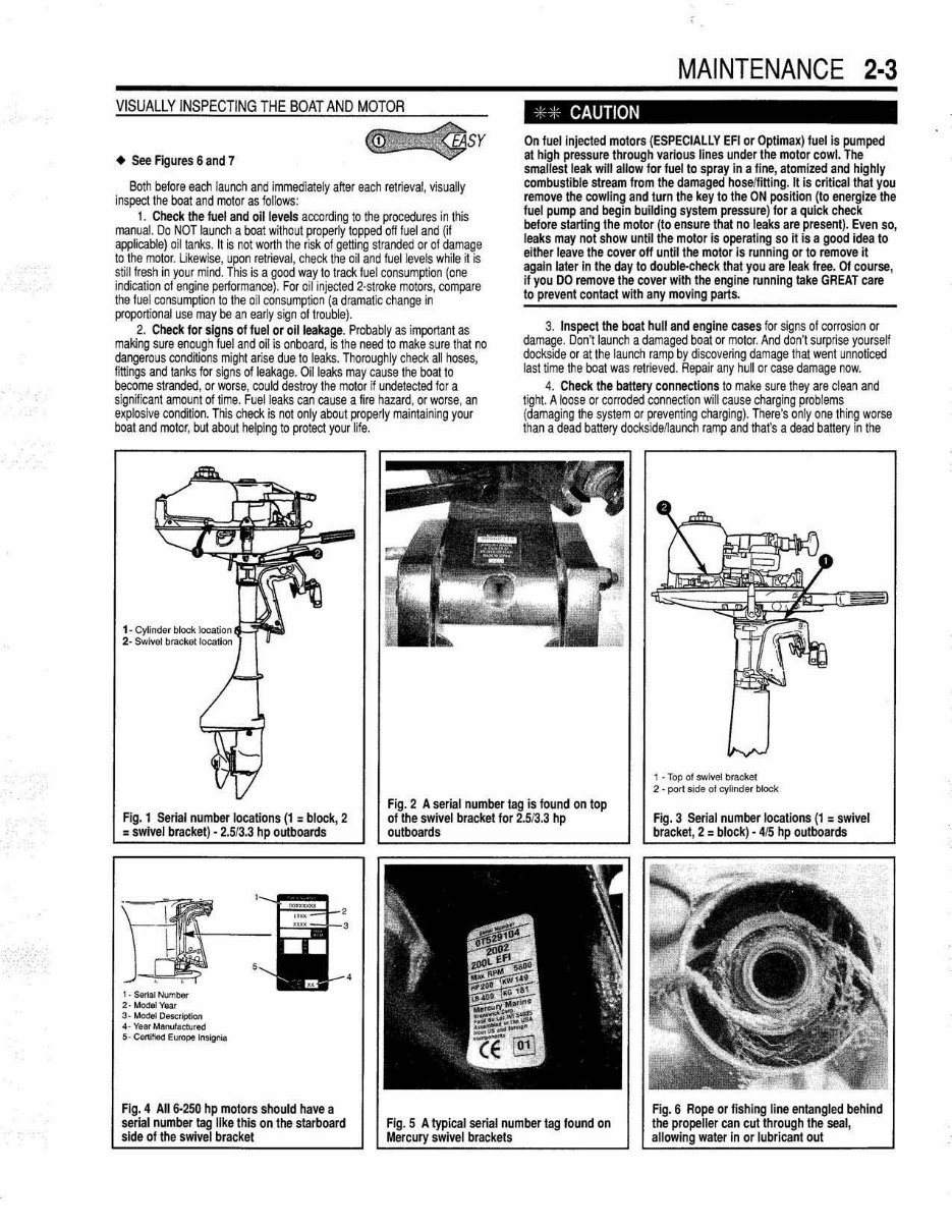
Engme (and Senal Number) Identificatton
• See Figures 1 thru 5
For many years the engine serial numbers were Mercury's key to engine
changes. These numbers identify the year of manufacture, the horsepower
rating and the paris boo k ident~ication. If any correspondence or paris are
required, it is still a good klea to use the engine serial number to make
SURE you get the right part.
However, we're happy to report that more and more Mercury has come in
line with other engine manufacturers and is slicking doser and closer to
model years than ever before. At l east one of the serial number tags used by
Mercury on their newer 2·strokes i ncludes a specifiC spot which displays the
MODEL YEAR of the mot or (along wHh the serial number, hp rating, weight
rating, and year of manufactural .
• Al so remember that the serial number tag estab lishes the model
year and th e y'ear In which the engine was produced which is (or are)
not necessarily the year of first installation.
Two serial numbers tags were placed on each of these mot ors. One is
attached to the powerhead itseH, usually on the lower starboard side of the
powerhead, but on some 75 hp and larger motors ~ may be instead affixed
to the TOP of the powerhead.
All motors are also equipped with a serial number ID tag on the swivel
bracket. For the smallest mot ors (2.5/3.3 hp models) this tag may be on the
top center of the swivel bracket, but for most Mercury motors it is found on
the starboard SIDE 01 the swivel bracket.
F or mora information on engine identification and specifications, please
refer to the General Engine Specifications charls later in this section.
Before After Each Use
As stat ed earlier. the best means of extending engine lile and helping to
protect your self while on the water is to pay close attention to boaVergine
maintenance. This starts with an inspection of syst ems and components
before and after each time you use your boat.
A list of checks, inspections or requi red maintenance can be found in the
Maintenance Intervals Chart at the end of this section. Some of these
inspectjons or t asks are performed before the boat is launched , some only
after it is retrieved and the rest , both times .
VISUAllY I NSPECTI NG T HE BOAT AND MOTOR
• See Figures 6 and 7
~SY
Both before each launch and immediately after each retrieval , vi sually
inspect the boat and motor as follows :
1. Check the fuel and oil levels according to the procedures in this
manual. 00 NOT launch a boat without properly topped off f uel and (i l
applicable) oil tanks. 1\ is not worth the risk of getting stranded or at damage
to the motor. Ukewlse, upon retrieval, check the oil and fuel levels while if is
still fresh in your mind. This is a good way 10 track fuel consumption (one
indica1ion 01 engine performance). For oil injected 2·stroke motors, compare
the fuel consumption 10 the oil consumption (a dramatic change in
proportional use may be an early sign of trouble).
2. Check lor signs of fuel or oil leakage. Probably as important as
making sure enough f uel and oil is onboard, is the need to make sure that no
dangerous conditions might arise due 10 leaks. Thoroughly check all hoses.
littings and tanks for signs of leakage. Oil leaks may cause the boat to
become stranded. or worse. could destroy the motor jf undetected for a
significant amount of time. Fuel leaks can cause a fire hazard, or worse, an
explosive condition. This check is not only about properly mai ntaining your
boat and motor, but about hetping to protect your tife.
MAINTENANCE 2-3
, CAUTION
On fuellnjecled motors (ESPECIAllY EFI or Optlmax) fuel is pumped
at high pr essure through various lines under the motor cowl. The
smallest leak will allow for fuel to spray in a fine, atomized and highly
combustible stream from the damaged hoselfilling. It is critical that you
remove the cowling and tum the key 10 Ihe ON position ( 10 energize the
fuel pump and begin building system pressure) for a quick check
before starling the motor (to ensure that no leaks are present). Even so,
leaks may not show until the molor is operating so II is a good idea to
either leave the cover off untillhe molor Is running or 10 remove it
again laler In the day to double-check thai you are leak tree. 01 course,
if you DO remove the cover with the engine running take GREAT care
10 prevent contact with any moving paris.
3. Inspect the boat hull and engine cases for signs 01 corrosion or
damage. Don't launch a damaged boat or motor. And don·t surprise yourseH
dockside or at the launch ramp by discovering damage that went unnoticed
last lime the boat was retrieved. Repair any hull or case damage now.
4. Check the battery connections to make sure they are clean a nd
tight. A loose or corroded connection will cause charging problems
(damaging the system or preventing charging). There's only one thing worse
than a dead battery docks1deJIaunch ramp and thaI's a dead battery in the
, • Top of $Wi ..... bracket
2 . port side ot cylind",. bIocl<
Fig. 1 Serial number locations (1 = block, 2
= swivel bracket) - 2 .513 .3 hp outboards
Fig. 2 A serial number tag is found on top
of the swivel bracket for 2 .513 .3 hp
outboards
Flg. 3 Serial number locations (1 = swivel
brackel, 2 = block) - 415 hp outboards
, . SariaI Number 2· __
3._~
4· Y_ ManuT_o:rure<l
5· CenIti«I Europe lnsIgnio
Flg.4 All 6-250 hp motors should have a
serial number tag like this on the starboard
side of the swivel bracket
serial number lag found on
Fig. 6 or fishing line entangled behind
the II cut through the seal,
water In or lubricant out
2-4 MAINTENANCE
middle of a bay, river or worse, the ocean. Whenever possible , make a q uick
visual check of battery electrolyte levels ( keeping an eye on the lavel will
give some w arning of overcharging pr oblems). This is especi ally true ~ the
engi ne is operated at high speeds for extended periods of time.
5. Check the propeller (Impeller on jet drives) and gearcase. Make
sure the propeller shows no signs of damage. A broken or bent propeller
may allow the engine to over·rev and it will certai nly waste fuel. The
gearcase should be checked before and after each use lor si gns of leakage.
Ch eck the gearcase oil for signs 01 ronlamination ff any l eak age is noted.
Also, visually ch eck beh ind the propeller for signs of enlangled rope or
fishi ng lines that could CUl1hrough the lower gearcase propeller shaft seal.
This is a common cause 01 gearcase lubricanl l eakage, and eventually, w ater
contaminati on that can lead to gearcase failure. Even ff no gearcase leakage
is noted w hen the boat is first retrieved, check again next time betore
launching . A n ick ed seal might not seep Huid right away when still swollen
from heat i mmediately after u se , but might begin seeping over the next day,
w eek or month as ij sal, coo'ed and dried out.
6. Check aU accessible fasteners for tightness. Make su re all easily
accessi bie lasteners appear to be tight. This is especially true tor the
propell er nut, any anode retaining bolts, all steering or th rott le li nkage
lasteners and the engi ne cl amps or mounting bo~s. Don't risk loosing control
or becoming stranded due to loose fasteners. Perform these checks before
h eading out, and immediately after you return ( so you' ll know it anything
needs to be serviced before you want to lau nch again .)
7. Check operation of all controts including the throtlle/shlf1er ,
steering and emergency stopfstar1 switch and/ or safety lanyard. Betore
launching, make su re that all linkage and steeri ng components operate
properly and move smoothly th rou gh their range of motion. AU electrical
switches ( such as power trimtti lt) and especially the emergency stop
system(s) must be in proper working order. While u nderway, walCh for signs
that a syst em is not working or has become damaged. With the steering ,
shifter or throttle, keep a watchful eye out for a change in resistance or the
start of jerkytnotchy movement.
8. Check the water pump intake grate and wat er Indicator. The
water pump intake grate shou ld be clean and u rdamaged before selling out
Remember that a damaged grate coul d allow debris i nto the system that
cou ld destroy the impeller or dog coo l ing passages. Once underway, make
sure the cooling indicator stream is visi bie at all limes. Make periodic ch ecks,
includi ng one final check before the motor is shut down each time. If a
cool ing indicat or stream is not present at any point, troubieshoot the problem
before further engi ne operation.
LUBRICATION
About Lubrication
• See Figure 8
An ou tboard motor's greatest enemy is corrosion. Face ij, oil and water
just don1 mix and , as anyone who has visited a junk yard MOWS, metal and
water aren't the greatest 01 friends either . To expose an engine to a h arsh
marine env i ronment of w ater and wind is to expect that th ese elements will
take their toll over time. But, there is a way to fight back and help prevent the
natural process of corrosion that will destroy your beloved boat motor.
Various marine grade lu bricants are available that serve two important
functions in preserving your mot or . Lubricants reduce fr iction on metal-to-
metal contact surlaces and. th ey al so displace air and moisture, therefore
slowing or preventing corrosion damage. Periodic lubrication services are
your best method of preserving an outboard motor. Marine lubricants are
desi gned for the harsh environment to which outboards are exposed and are
designed to stay in place, even when submerged in water (and we've got
some bathing sui ts with marine grease stains to a tt est to this).
Lubrication takes pl ace through various forms. For a ll engi nes. i nternal
moving parts are l ubricated by engine oil, in the case of 2-stroke motors it is
th rough oil contained in the fuell oil mixture. Also, on all conventional motors
( as opposed to jet drives) the gearcase is fiJled with gear oil that lubricates
the driveshaft, propshaH, gears and other internal gearcase components.
The gear oil should be peri odically checked and replaced lollowing the
appropriate E ngi ne Maintenance procedures. Perlonn these services based
on time or engine use, as outl i ned in the Maintenance Intervals chart at the
end of this secti o n.
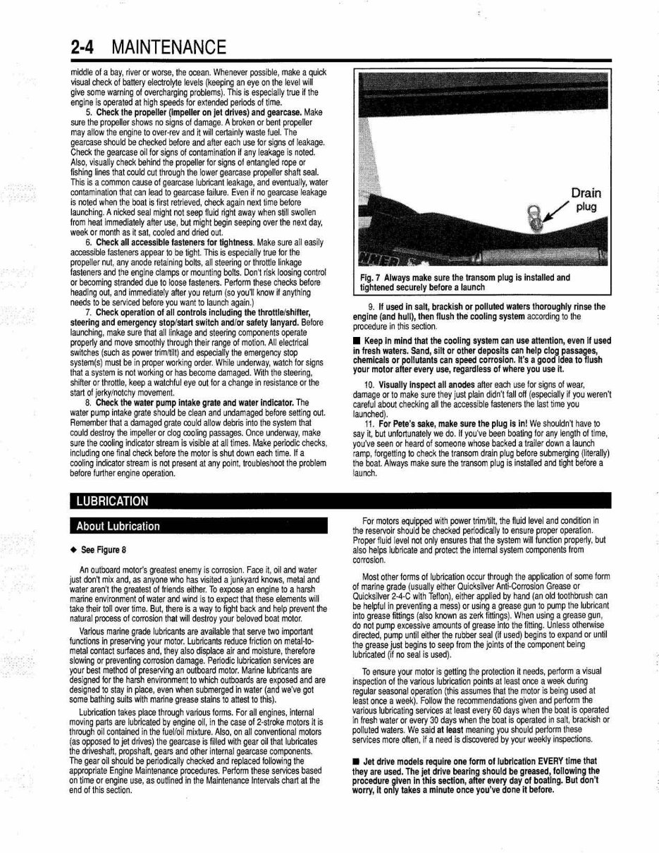
Afwa ys make sure the transom plug Is installed and
launch
9. If used In sail, brackish or poHuled walers Ihoroughly rinse the
engine ( and huH), then flush the cooling system according to the
procedure in this section.
• Keep In mind that the cooling syslem can use al tenllon, even if used
in fresh waters. Sand , silt or other deposits can help clog passages,
chemicals or pollutants can speed corrosion . II's a good idea 10 flush
your motor after every use, regardless of where you use it.
10. Visually Inspect all anodes after each use for signs of wear,
damage or to make su re they just plain didn't f all off ( especiall y ~ you w eren't
caref ul about checklng all the accessible fasteners the last time you
launched).
11 . For Pete's sake, make sure the plug Is In! We shouldn't h ave to
say it, but unfortunately we do. If you've been boating for any length of lime ,
you 've seen or heard of someone whose back ed a trailer down a launch
ramp, forgetting to check the transom drain plug before submerging ( literally)
the boat Always make sure the transom plug is installed ard ti ght before a
lau nch.
For motors equipped wi th pow er tri mltilt, the nuid levei and condition in
the reservoir shoul d be check ed periodical ly to ensure proper operation.
Pr oper fluid level not only ensures th at the system wi ll function properly, but
also hel ps lubri cate and protect the internal system components from
corrosion.
Most oth er lonns 01 lubrication occur through the application of some fonn
of marine grade ( usually either Qui cksi lver Anti-Corrosion Grease or
Quicksilver 2·4-C wi th Tefl on ), either appli ed by hand (an old toothbrush can
be helpful in preventing a mess) or using a grease gun to pump the lubricant
into grease fittings (also known as zerlo; fittings). When using a grease gun ,
do not pump excessive amounts of grease into the f rtl ing. Unless otherwise
directed, pump unlit either the rubber seal (i f used) begins to expand or until
the grease just begins to seep from the joints of the romponent being
lubricated (il no seal is used).
To ensure your motor is getti ng the protection ~ needs, perfonn a visual
inspection of the various lubricalion points at least o nce a week during
regular seasonal operation ( this assumes that the motor is being used at
least once a week). Follow the r ecommendations given and perlorm the
various lubricating services at least every 60 days when the boat is operated
in fresh water or every 3{) days when the boat is operated in salt, brack ish or
polluted waters. We sa id at least meaning you should perform th ese
services more often. H a need is di scovered by your weekly inspections.
• J et drive models require ooe form of tubrlc al ion EVERY time thal
they are used. The jet drive bearing shoutd be greased , followinglhe
procedure jlV en In this section, after every day of boating. But don 't
worry, it on y takes a minute once you've done it before.
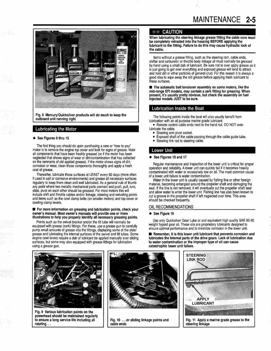
Fig. 8 Mercury/Quic ksil ver products will do much to keep the
outboard unit running right
lubricating the Motor
• See Figur es 9 thru 15
The first thing you should do upon purchasing a new or "new 10 you'
molor is to remove the engine top cover and look for signs of grease, Nole
all COfTllOllents that have been freshly greased (or if the motor has been
neglected that shows signs of wear or dirVcontamination thai has collected
on the remnants of okl applied grease). If the motor shows signs of dirt,
corrosion or w ear, dean those components thoroughly and apply a Iresh
coat of grease.
Thereafter, lubricate those surfaces at LEAST every 60 days (more often
if used in salt or corrosive environments) and grease all necessary surfaces
regul arly to keep them clean and well lubricated. As a general rule of Ihurrb
any point where two metallic mechanical parts connect and push , pul l, lum,
slide, pivot on each other should be greased. For most motors this w ill
incl u de shifl and throttle cables and/or linkage, steering and swiveling points
and items such as the cowl damp bolts (on smaller motors) and top cover or
cowling clamp levers.
• For more information on greaslng and lubrication poI nts, check your
owner"s manual. Most owner's manuals will provide one or more
UluslraUons to help you properly ldenUfy all necessary greasing poInts.
Points such as the swivel bracket and/or the tilt tube will normally be
equipped with grease (zerk) littings. For these, use a grease gun to carelully
pump small amounts of grease into the littings, displacing some of the older
grease and lubricating the intemal surfaces of the swivel and ti~ tubes. Some
engine cowl levers require a dab of lubricant be applied manually over sliding
surfaces, but some may also equipped with grease fittings for lubrication
using a grease gun.
MAINTENANCE 2·5
· - CAUTION
When lubricating the steering linkage grease fitting Ihe cable core must
be completely retrac1ed Inlo the housing BEFORE applying the
lubricant 10 the fitting. Failure to do this may cause hydraulic lock of
the cable.
Items without a grease fitting, such as the steering ram, cable ends,
shifter and carburetor or throttle body li nkage all must normally be greased
by hand using a small dab of lubricant. Be sure not to over apply grease as H
is just going to get over everything and exposed grease will tend to attract
and hold dirt or other particles of general crud. For this reason it is always a
good idea to wipe aw ay the old grease before applying fresh lubricant to
these surfaces.
• The automatic belilensioner assembly on some motors, like the
mid· range EFI models, may contain a zerk fitting for greasing. When
present, it's usually pretty obvious, but check the assembly on fuel
Injected models JUST to be sure.
Lubrication InSide the Boat
The following poi nts inside the boal will also usual ly benefit from
lubrication with an all purpose marine grade lubricant:
• Remote control cable ends n9}:t to the hand nut. DO NOT over-
lubricate the cable.
• Steering arm pivot socket.
• Exposed shaft 01 the cable passing through the cable guide tUbe .
• Steering link rod to steering cable.
Lower Unit
• See Figures 16 and 17
Regular maintenance and inspection of the lower unit is critical for proper
operation and reliability . A lower unit can quickly fail if it becomes heavi ly
contaminated with water or excessi vely Iow an oil. The most common cause
of a lower uni t failure is w ater contaminati on .
Water in the low er unit is usual ly caused by fishing line or other f oreign
material, becoming ent angl ed around the propeller shah and damaging the
seal. If the l ine is not removed , ~ wil l eventually cut the propeller shaft seal
and allow water to enter the lower uni t. FIShi ng line has also been known 10
cut a groove in Ihe propel ler shah if left negl ected over time. This ar ea
should be checked frequently.
O IL RE COMM ENDA T IONS
• See Figure 18
Use only Quicksilver Gear Lube or and equivalent high quality SAE 85·90
weight hypoid gear oil. These oi ls ale proprietary lubricants designed to
ensure optimal performance and to minimize corrosion in the lower unit.
• Remember, it is thi s lower unit lubricant Ihat prevents corrosion and
lubricates the internal parts of the drive gears. Lack of lubrication due
to water contamination or the Improper type of all can cause
catastrophic lower unit failure.
Fig . 9 Various lubrication points on the
powemead should be maintained regularly
to ensure a long service life including all
rotallng . ..
Fig. 10 ••• or sliding linkage points and
cable ends
2-6 MAINTENANCE
CHECKING GE A RCA SE OIL LEVEL & CONDI T ION
• See Figures 19 and 20
~SY
Visually inspect the gearcase before and after each use tor signs of
leakage. At least monthly, or as needed , remove the gearcase level plug in
order to check the lubricant le vel and condition as follows:
I. Position the engine in the upright position wi th the motor shut off for
alleasl1 hour. Whenever possible, checking the level overnight cold will
give a true indica~on 01 the level w ithout having to account f or heat
expanSion.
2. Disconnect the negative banery cable or remove the propeller for
safety.
CAUTION
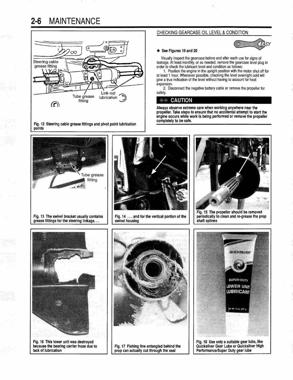
12 Steering cable grease fitting s and pivot poinllubricalion
Always observe extreme care when working anywhere near the
propeller. Take steps to ensure lhal no accIdental allempllo start the
engine occurs whil e work Is being performed or remove the propeller
completely to be sale.
Fig. 13
grease
II contains
Fig. 16 This low er unit was destroyed
because the bearing carrier froze due to
lack 01 lubrication
Fig. 17 Fishing line entangled behind the
prop can actually cut through the seal
3. Position a small drain pan under the gearcase, toon unthread the
drainlfiller plug al the bottom of the housing and allow a small sample (a
teaspoon or l ess) to drain from the gear cast!. Quickly inSlalllhe drain/filler
plug and tight en securely.
4. Examine the gear oil as fol lows:
a. Visually check the oi l for obvious signs of water. A small amount 01
moisture may be present from condensation, especiall y if a motor has been
stored for some ti me, but a milky appearance ind i cates that either the fluid
has not been changed in ages or the gearcase allowing some water to
intrude. If significant water contamination is present, the firs t suspect is the
propeller shaft seal.
b. Dip an otherwise cl ean finger into the oil, then rub a small amount 01
the fluid between your finger and your thumb to check for the presence of
debris. The lubricant should feel smoot h. A very small amount 01 met allic
shavirgs may be present, but should not really be f eM. large amounts of grit
or met allic partides indi cate the need to overhaul the gearcase looking for
damaged!wom gears, shafts, bearings or thrust surfaces.
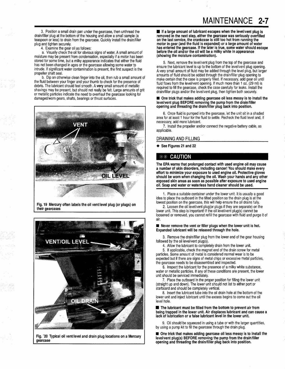
Fig. 19 Mercury often labels the oil vent/level plug (or plugs) on
their
Fig. -20 Typical oil ventilevel and drain plug locations on a Mercury
gearcase
MAINTENANCE 2-7
• If a large amount 01 lubricant escapes when the level/vent plug is
remo v ed In the nen step, either the gearcase was seriously overfilled
on the last servIce, the crankcase is slilltoo hot from runnI ng the
molor in gear (and the lIuid is expanded) or a large amount 01 water
has entered the gearcase. If the later is true, some water should escape
before the 011 and/or the oil will be a milky white in appearance
(showing the moisture contamination).
5. Next, remove the leveVvent plug Irom the lop of the gearcase and
ensure the lubricanllevel is up to the bottom of the leveVvent plug opening.
A very smal l amount of fluid may be aclded through the level plug, but l arger
amounts of fluid should be added through the drainlfiller plug opening to
make certain that the case is pr operly filled. If necessary, acid gear oil unt il
fluld flows from the IeveVvent opening. If much more than 1 oz. (29 ml) is
required to fill the gearcase , check the case carefully for leaks. InstaJl the
drainlfiller plugs and/or the leveVvent plug , then tighten both securely.
• One trick that makes adding gearcase oil less messy is to install the
level / vent plug BEFORE removing the pump from the drainlfiller
opening and threading the drainJfilier plug back into position.
6. Once fluid is pumped into the gearcase, let the un~ si t in a shaded
area f or at least 1 hour lor t he lIuid to settle. Recheck the lIuid level and, il
necessary, add more lubricant.
7. Install the propeller and/or connect the negative battery cable, as
applicable.
DRAINING AND FI L LING
• See Figures 21 and 22
CAUTION
The EPA warns that prolonged contact with used engine oil may cause
a number of skin disorders, including cancer! You should make every
effort to minimize your exposure to used engine oil. Protec1ive gloves
should be wom when changing the 011. Wash your hands and any other
exposed skln areas as soon as possible after exposure to used engine
oil. Soap and water or waterless hand cleaner should be used.
1. Place a suitable container under the lower un~. n is usua lly a good
idea to place the outboard in the @ed pos~ion so the drain plug is at the
lowest pos~ion on the gearcase, this will help ensure the oil drains fully.
2. Loosen the oilleveVvent plug ( or plugs if they are separate) on the
lower unit. This step is important! II the oilleveVvent plug (s) cannot be
loosened or removed, you cannot refill the gearcase w~h fluid and purge ~ of
air.
• Never remove the vent or filler plugs when the lower unit is hot.
Expanded lubricant will be released through the hole.
3. Remove the drainlfill er plug from the lower end of the gear housing
followed by the oillevelfvent plug(S).
4. Allow the lubricant to completely drain from the lower unit.
5. If applicabfe, check the magnet end of the drain screw lor metal
particles. Some amount of metal Is considered nor mal wear is to be
expected but ~ there are si gns of metal chips or excessive metal particl es,
the gearcase needs to be disassembled and inspected.
6. Inspect the lubricant for the presence of a milky wMe substance,
water or metallic particles. II any of these cond~ions are present, the lower
un~ should be serviced i mmediately.
7. Place the outboard In the proper pos~ion for filling the lower un~
(straight up and down) . The lower unit should not list to either port or
starboard and should be completely vertical.
8. Insen the lubricant tube into the oil drain hole at the bottom of the
lower un~ and injed lubricant until the excess begins to come out the oil
l evel hote.
• The lubricant must be IUled from the bottom to prevent air from
being trapped in the lower unit . Air displaces lubricant and can cause a
lack of lubrication or a false lubricant level in the lower unit.
9. Oil should be squeezed in using a tube or with the larger quantities,
by using a pump kit to fill the gearcase thr ough the drain p lug.
• One Irick that makes adding gearcase 011 less messy is 10 install the
level /Vent plug(S) BEFORE removing the pump from the drainlfiller
opening and threading the drainlfiUer plug back into position.
2-8 MAINTENANCE
10. Using new gasketslwashels (~equipped) install the oil JeveV venl
pl ug(sj first, then instalilhe oil fill plug.
11. Wipe the excess oil from the lower un it and inspect the unit for leaks.
12. Place the used lubricant in a suitable container for transportation to
an authorized recycling facility.
Jet Drtve Bearing
• See Agure 23
Jet drive models requ i re special attention 10 ensure that the driveshaft
bearing remains properly lubricated .
Mercury recommends that you lubricate the jet drive bearing using a
grease gun after EACH days use. However, at an absolute minimum, use the
grease fitting every 10 hours (in fresh water) or 5 hours (in salt water). Also,
after about every 30 hours of qleraflon, the dr ive bear ing grease must be
replaced. Follow the appropriate procedure:
RECOMMENDED LUBRICANT
Use Quicksi l ver 2·4-C with Tellon or an equival ent water-resistant NlGI
No . t lubricant.
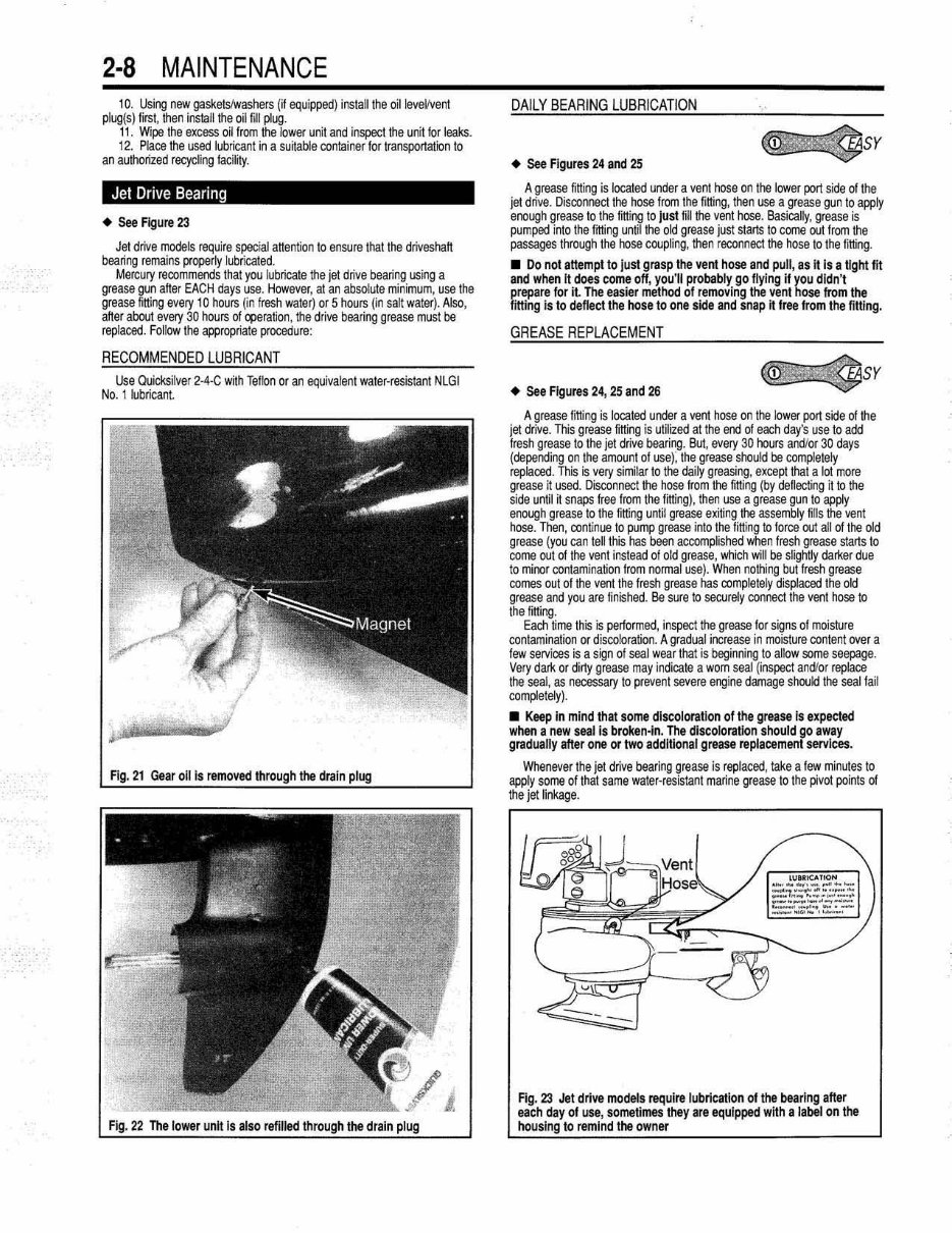
Flg. 21 Gear 011 is the drain
F ig. 22 The lower unh is I the drain
DAILY BEARING LU BRICATI ON
• See FiQures 24 aoo 25
~SY
A grease fitting is located under a vent hose on the lower port side of the
jet drive. Disconnect the hose from the fitting, then use a grease gun to apply
enough grease to the fitt i ng to Just fill the vent hose. BaSically, grease is
pumped into Ihe fming until the old grease just slarts to come out Irom the
passages through Ihe hose coupling, then r econnect the hose to the fitting .
• Do not atte mpt to Just grasp the vent hose and pull, as it iii a UglYt lit
and when It does come off, you'll probably go Hying if you didn't
prepare for it. The easier method of removing the vent hose from the
litting is to deflect the hose to one side and snap it lree from lhe IiIUng.
GREASE REPLACEMENT
• See Figures 24, 25 and 26
~SY
A grease fitting is located under a vent hose on the loWE!( port side of the
jet drive. This grease fitting is utilized at the end of each day's use to add
fresh grease to the jet drive bearing. But, (!Very 30 hours andlor 30 days
(depending on the amount of use): the grease should be completely
replaced. This is very similar to lhe daily greasing, except that a lot more
grease it used. Disconnect the hose from lhe fitting (by deflecting illo the
side until ij snaps froo from the filting), Ih en use a grease gun to apply
enough grease to the filting unti! grease exiting the assembly fi l ls the venl
hose. Then, continue to pump grease into the fitting 10 torce out all of the old
grease (you can tell this has been accomplished when fresh grease starts to
come out of the vent instead ot old grease, which will be slightly darker due
to minor contamination trom normal use). When nothing but fresh grease
comes out of the vent the fresh grease has completely displaced the old
grease and you are finished. Be sure 10 securely connect the vent hose 10
the filling.
Each time this is performed, inspect the grease for signs of moisture
conlamination or discoloration. A gradual increase in moisture conlent over a
few servlces is a sign of seal w ear that is beginning to allow some seepage.
Very dark or dirty grease may indicate a worn seal (inspect and/or replace
the seal, as necessary to prevent severe engi ne damage should the seal fail
completely) .
• Keep in mind that some discoloration 01 the grease is expeC1ed
when a new seal is broken-In. The discoloration shoul d go away
gradually after one or two additional grease replacement services.
Whenever the jet drive bearing grease is replaced, take a tew minutes to
awly some of that same water-resistant marine grease to the pivot points of
the jet linkage.
--
-
Fig. 23 Jet dri ve models require lubrication of the bearing after
each day 01 use, sometimes they are equI pped with a Jabel on the
housing to remind the owner
You're Reading a Preview
What's Included?
Fast Download Speeds
Online & Offline Access
Access PDF Contents & Bookmarks
Full Search Facility
Print one or all pages of your manual
$39.99
$51.99
Viewed 57 Times Today


Secure transaction
What's Included?
Fast Download Speeds
Online & Offline Access
Access PDF Contents & Bookmarks
Full Search Facility
Print one or all pages of your manual
$39.99
$51.99
- The 2001-2005 Mercury Mariner 2.5HP to 225HP Outboards Service & Repair Manual is a comprehensive resource for fixing problems on your outboard, providing troubleshooting and replacement procedures recommended by the manufacturer.
- It includes step-by-step instructions, clear images, and exploded-view illustrations to assist both professional mechanics and DIY enthusiasts in maintaining and repairing their outboard.
- Regular maintenance is essential for outboards, and this manual offers the manufacturer's recommended troubleshooting charts and replacement procedures to ensure the outboard's reliability.
- With this manual, you can save on repairs, increase your outboard's reliability, and effectively address issues as they arise.
- Conveniently, the manual eliminates the need to search through numerous pages, providing easy access to specific information without the risk of damage or loss.
- It is available in a printable format and compatible with various electronic devices, including PC & Mac computers, Android and Apple smartphones & tablets, etc. The only requirement is Adobe Reader, which is free to use.


