

HONDA BF90A BF90 OUTBOARD OWNER Owners Manual
What's Included?
Fast Download Speeds
Online & Offline Access
Access PDF Contents & Bookmarks
Full Search Facility
Print one or all pages of your manual
© HONDA MOTOR CO., LTD. 1995
BF75A/90A
Owner’s
Manual
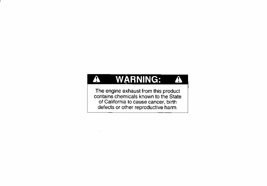
The engine exhaust from this product

Thank you for purchasing a Honda
Outboard Motor.
This manual describes the operation
and maintenance of the Honda
BF 75A and BF 90A Outboard
Motors.
All information in this publication is
based on the latest product informa-
tion available at the time of printing.
Honda Motor Co., Ltd. reserves the
right to make changes at any time
without notice and without incurring
any obligation.
No part of this publication may be
reproduced without written
permission.
This manual should be considered a
permanent part of the Outboard Motor
and it must stay with the Outboard
Motor if resold.
SAFETY MESSAGES
Your safety and the safety of others are
very important. We have provided
important safety messages in this
manual and on the outboard motor.
Please read these messagescarefully.
A safety message alerts you to poten-
tial hazards that can hurt you and
others. Each safety message is preceded
by a safety alert symbol A and one of
three words: DANGER, WARNING,
or CAUTION.
These mean:
B
You WILL be
KILLED or SERIOUSLY HURT
if you don’t follow instructions.
-
You CAN be
KILLED or SERIOUSLY HURT
if you don’t follow instructions.
-
You CAN be HURT
if you don’t follow instructions.
Each message tells you what the hazard
is, what can happen, and what you can
do to avoid or reduce injury.
DAMAGE PREVENTION
MESSAGES
You will also see other important
messages that are preceded by the
word NOTICE.
This word means:
NOTICE Your outboard motor
or other property can be damaged
if you don’t follow instructions.
The purpose of these messages is to
help prevent damage to your outboard
motor, other property, or the
environment.
HONDA MOTOR CO., LTD. 1995
ALL RIGHTS RESERVED
1
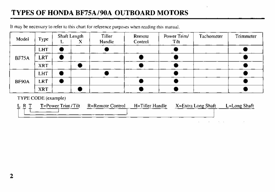
TYPES OF HONDA BF75AIBOA OUTBOARD MOTORS
It may be necessary to refer to this chart for reference purposes when reading this manual.
TYPE CODE (example)
LRT T=Power Trim /Tilt R=Remote Control H=Tiller Handle X=Extra Long Shaft L=Long Shaft
TT,
2
IDENTIFICATION NUMBERS
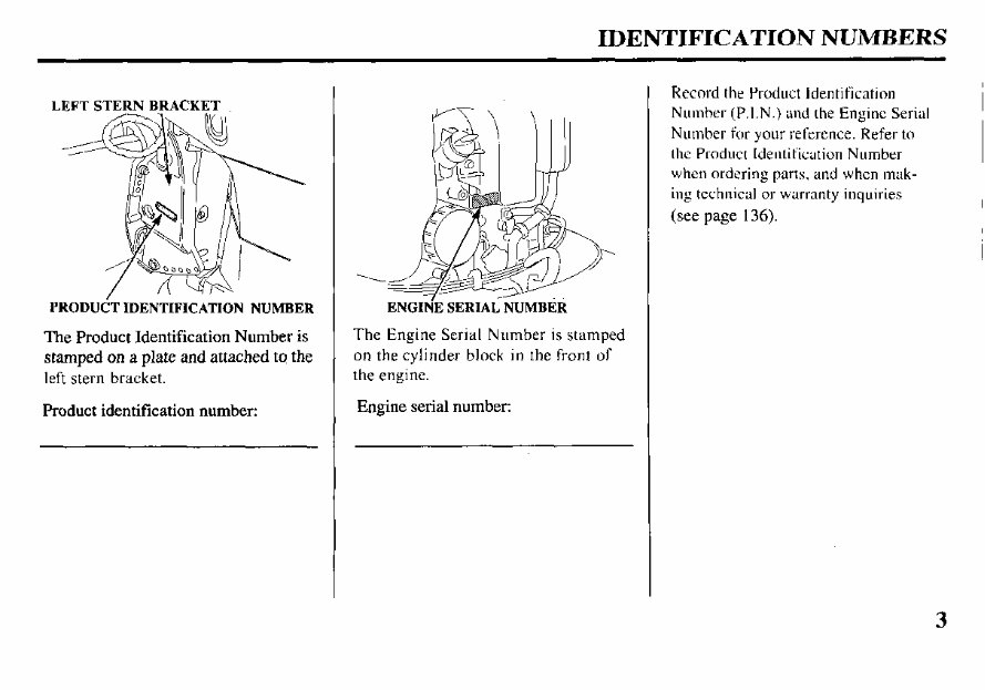
LEFTSTERNBRACKET
PRODUdT IDENTIFICATION NUMBER
The Product Identification Number is
stampedon a plate and attached to the
left stern bracket.
Product identification number:
ENGIN’E SERIAL NUMBER
The Engine Serial Number is stamped
on the cylinder block in the front of
the engine.
Engine serial number:
Record the Product Identification
Number (P.I.N.) and the Engine Serial
Number for your reference. Refer to
the Product Identification Number
when ordering parts, and when mak-
ing technical or warranty inquiries
(see page 136).
CONTENTS
1. SAFETY
SAFETY LABELS.. ...................
SAFETY INFORMATION.. ......
2. COMPONENT IDENTIFICATION ...
3. CONTROLS & INSTRUMENTS
TILLER HANDLE TYPE
Ignition Switch ...........................
Gear Shift Lever.. .......................
Choke Knob ................................
Throttle Grip.. .............................
Throttle Opening Indicator.. .......
Throttle Friction Knob ...............
Engine Stop Switch ....................
Emergency Stop Switch Lanyard ..
Oil Pressure Indicator Light .......
Overheat indicator Light ............
Power Trim/Tilt Switch.. ............
Steering Friction Adjuster ..........
REMOTE CONTROL TYPE
(SIDE-MOUNT TYPE)
Remote Control Lever.. ..............
Neutral Release Lever ................
Ignition Switch ...........................
Emergency Stop Switch Lanyard ..
Choke/Fast Idle Lever ................
Manual Choke Knob ..................
Oil Pressure IndicatorLight/Buzzer ....
Overheat Indicator Light/Buzzer ...
Power Trim/Tilt Switch.. ............
4
6
7
8
14
I4
I4
I5
I5
15
16
I6
17
I7
18
18
I9
20
20
;:
22
23
23
24
(PANEL-MOUNT TYPE)
Remote Control Lever.. .............. 25
Nertral Release Lever.. ............... 26
Ignition Switch ........................... 26
Emergency Stop Switch Lanyard 27
Throttle Button ........................... 28
Choke Switch ............................. 28
Manual Choke Knob .................. 28
Oil Pressure Indicator Light/Buzzer .... 29
OverheatIndicator Light/Buzzer.. .... 29
Power Trim/Tilt Switch.. ............ 30
(TOP-MOUNT TYPE)
Remote Control Lcvcr ................ 3 I
Ignition Switch ........................... 32
Emergency Stop Switch Lanyard 33
Throttle Button ........................... 34
Choke Switch ............................. 34
Manual Choke Knob .................. 34
Oil Pressure Indicator Light/Buzzer.... 35
Overheat Indicator Light/Buzzer.. . 35
Power Trim/Tilt Switch
(remote control lever). . 36
Power Trim/Tilt Switch
(control box console). .. 36
COMMON
Power Tilt Switch (engine pan). . 37
Trim Meter.. ...................................... 37
Tachometer (optional equipment) .. 37
Manual Relief Valve .................. 38
Tilt Lock Lever.. ......................... 39
Trim Tab ..................................... 39
Anode Metal ............................... 40
Cooling System Indicator ........... 40
Water Intakes .............................. 40
Transom Angle Adjusting Rod .. 41
Fuel Cap/Gauge/Vent Knob
(optional fuel tank) .. 42
Over-Rev Limiter ....................... 42
Engine Cover Lock Lever .......... 43
Fuel Host Connector .................. 43
4. PRE-OPERATION CHECKS
Engine Cover Removal/Installation.. 44
Engine Oil ..,............................... 45
Fuel Level (optional fuel tank) ... 46
Fuel Recommendations .............. 47
Oxygenated Fuels ....................... 48
Propeller and Cotter Pin Inspection .. 49
Steering Friction Adjustment
(TILLER HANDLE TYPE) .. 50
Remote Control Friction
Adjustment ................................. 50
Engine Cover Lock Lever
Adjustment .. 51
Other Checks
l Stem bracket ............................ 52
l Tool Kit .................................... 52
l Anodes ,........,.......................,,.. 52
5. STARTlNG THE ENGINE
Optional Fuel Tank ..................... 53
Fuel Line Connection ................. 53
CONTENTS
STARTING THE ENGINE
(TILLER HANDLE TYPE) .... 55
STARTING THE ENGINE
(REMOTECONTROLTYPE) ... 60
(SIDE-MOUNT TYPE) .......... 60
(PANEL-MOUNT TYPE) ...... 63
(TOP-MOUNT TYPE) ............ 66
STARTING THE ENGINE
(EMERGENCY STARTING). 69
Troubleshooting Starting Problems.. 74
6. OPERATION
Break-in Procedure ..................... 75
TILLER HANDLE TYPE
Gear Shifting ........................... 76
Steering .................................... 76
Cruising ................................... 77
REMOTE CONTROL TYPE
(SIDE-MOUNT TYPE)
Gear Shifting ........................... 78
Cruising ................................... 79
(PANEL-MOUNT TYPE)
Gear Shifting ........................... 80
Cruising ................................... 81
(TOP-MOUNT TYPE)
Gear Shifting ........................... 82
Cruising ................................... 83
POWER TRIM/TILT
Power Trim/Tilt System ........ 84
Trim Meter .............................. 86
Power Tilt Switch (engine pan) ... 87
Manual Relief Valve ............... 87
Tilt Lock Lever.. ...................... 88
Trim Tab Adjustment .................. 89
MOTOR PROTECTION SYSTEM
Engine Oil Pressure and
Overheat Warning System ...... 90
Over-Rev Limiter .................... 92
Anodes ..................................... 92
Shallow Water Operation ........... 93
High Altitude Operation ............. 94
7. STOPPING THE ENGINE
TILLER HANDLE TYPE.. ........ 95
REMOTE CONTROL TYPE
(SIDE-MOUNT TYPE) ............. 96
(PANEL-MOUNT TYPE) ......... 97
(TOP-MOUNT TYPE) ............... 98
8. TRANSPORTING ...................... 99
9. CLEANING AND FLUSHING . 102
IO. MAINTENANCE ....................... 104
THE IMPORTANCE OF
MAINTENANCE .................... I04
MAINTENANCE SAFETY ....... 104
EMISSION CONTROL
SYSTEM INFORMATION.. .. 105
Tool Kit and Spare Parts ............ 108
MAINTENANCE SCHEDULE.. .. 109
Engine Oil ............................... 111
Gear Oil ................................... 113
Spark Plugs .............................. 115
Battery (not included) .............. 116
Lubrication .............................. 118
Engine Fuel Filter.. .................. 12 1
Fuel Tank and Filter ................ 123
Fuse Replacement ................... 124
Propeller .................................. 125
Submerged Motor.. .................. 126
11. STORAGE.. ................................ 128
12. TROUBLESHOOTING ............. 132
13. SPECIFICATIONS .................... 134
14. WARRANTY SERVICE ........... 136
15.INDEX.. ...................................... 137
16. WIRING DIAGRAM ................. 14 1
5
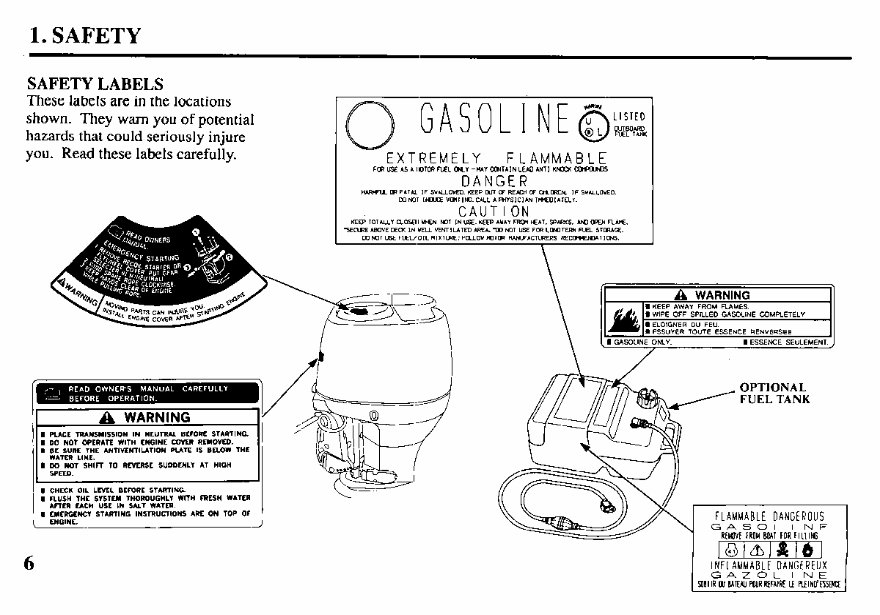
1. SAFETY
SAFETYLABELS
These labels are in the locations
shown. They warn you of potential
hazards that could seriously injure
you. Read these labels carefully.
FUEL TANK
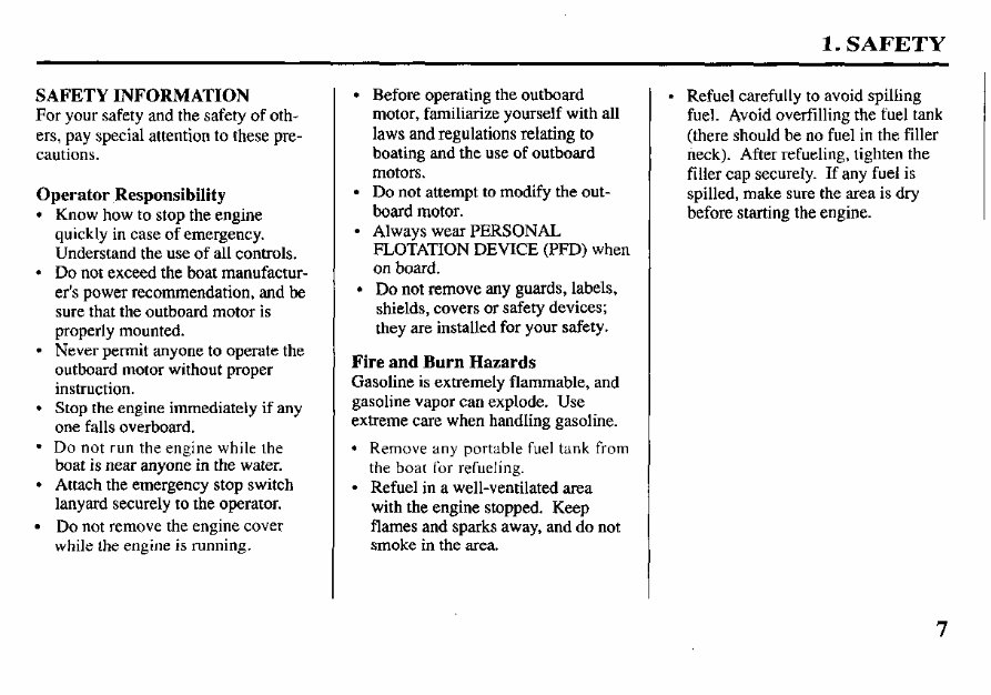
1. SAFETY
SAFETY INFORMATION
For your safety and the safety of oth-
ers, pay special attention to these pre-
cautions.
Operator Responsibility
l Know how to stop the engine
quickly in caseof emergency.
Understand the use of all controls.
l Do not exceed the boat manufactur-
er’s power recommendation, and be
sure that the outboard motor is
properly mounted.
l Never permit anyone to operate the
outboard motor without proper
instruction.
l Stop the engine immediately if any
one falls overboard.
l Do not run the engine while the
boat is near anyone in the water.
l Attach the emergency stop switch
lanyard securely to the operator.
l Do not remove the engine cover
while the engine is running.
l Before operating the outboard
motor, familiarize yourself with all
laws and regulations relating to
boating and the use of outboard
motors.
l Do not attempt to modify the out-
board motor.
l Always wear PERSONAL
FLOTAmON DEVICE (PFD) when
on board.
l Do not remove any guards, labels,
shields, covers or safety devices;
they are installed for your safety.
Fire and Burn Hazards
Gasoline is extremely flammable, and
gasoline vapor can explode. Use
extreme care when handling gasoline.
l Remove any portable fuel tank from
the boat for refueling.
l Refuel in a well-ventilated area
with the engine stopped. Keep
flames and sparks away, and do not
smoke in the area.
l Refuel carefully to avoid spilling
fuel. Avoid overfilling the fuel tank
(there should be no fuel in the filler
neck). After refueling, tighten the
filler cap securely. If any fuel is
spilled, make sure the area is dry
before starting the engine.
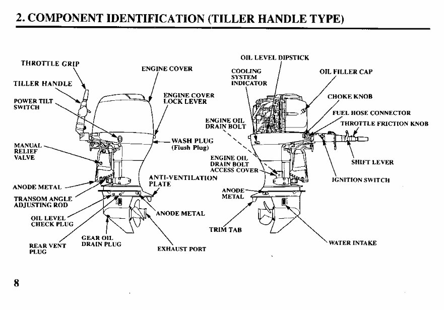
2. COMPONENT IDENTIFICATION (TILLER HANDLE TYPE)
THROTTLE GRIP
POWER TILT
ENGINE COVER
LOCK LEVER
L HOSE CONNECTOR
HROTTLE FRICTION KNOB
WASH PLUG
VALVE ENGINE OIL
DRAIN BOLT
HIFT LEVER
ACCESS COV
‘I-VENTILATION
NITION SWITCH
ANODE METAL
TRANSOM ANG
ADJUSTING RO
NODE METAL
/
GEAR OIL
REAR VENT
DRAIN PLUG
\
PLUG
EXHAUST PORT
\
WATER INTAKE
8
You're Reading a Preview
What's Included?
Fast Download Speeds
Online & Offline Access
Access PDF Contents & Bookmarks
Full Search Facility
Print one or all pages of your manual
$30.99
$40.99
Viewed 77 Times Today


Secure transaction
What's Included?
Fast Download Speeds
Online & Offline Access
Access PDF Contents & Bookmarks
Full Search Facility
Print one or all pages of your manual
$30.99
$40.99
- Outboard Motor Safety
- Important Safety
- Safety Label Location
- Controls and Features
- Control and Feature Identification
- Codes
- Component and Control Locations
- Controls
- LHT Type (tiller handle)
- Ignition Switch
- Emergency Stop Switch Clip and Emergency Stop Switch
- Throttle Grip
- Throttle Friction Adjuster
- Gearshift Lever
- Steering Friction Knob
- LRT and XRT Types (remote control)
- Side-Mount Type
- Ignition Switch
- Emergency Stop Switch Clip and Emergency Stop Switch
- Gearshift/Throttle Control Lever
- Fast Idle Lever
- Panel-Mount Type
- Ignition Switch
- Emergency Stop Switch Clip and Emergency Stop Switch
- Gearshift/Throttle Control Lever
- Fast Idle Button
- Top-Mount Type
- Ignition Switch
- Emergency Stop Switch Clip and Emergency Stop Switch
- Gearshift/Throttle Control Lever
- Fast Idle Button
- Common Controls
- Power Trim/Tilt Switch
- Power Tilt Switch
- Manual Relief Valve
- Tilt Lock Lever
- Engine Cover Latch (front/rear)
- Trim Tab
- Instruments
- Trim Meter (optional equipment)
- Tachometer (optional equipment)
- Speedometer (optional equipment)
- Indicators
- Alternator (ACG) Indicator
- Programmed Fuel Injection (PGM-FI) Indicator
- Oil Pressure Indicator
- Overheat Indicator
- Cooling System Indicator
- Other Features
- Water Separator Buzzer
- Overrev Limiter
- Portable Fuel Tank (optional equipment)
- Fuel Filler Cap Vent Knob (optional equipment)
- Fuel Priming Bulb (optional equipment)
- Anodes
- Before Operation
- Are You Ready to Get Underway?
- Is Your Outboard Motor Ready to Go?
- Tiller Handle Height/Angle Adjustment (LHT type)
- Operation
- Safe Operating Precautions
- Break-in Procedure
- Portable Fuel Tank (optional equipment)
- Fuel Hose Connections
- Fuel Priming
- Starting the Engine
- LHT Type (tiller handle)
- LRT and XRT Types (remote control)
- Side-Mount Type
- Panel-Mount Type
- Top-Mount Type
- Emergency Starting
- Stopping the Engine
- Emergency Engine Stopping
- Normal Engine Stopping
- Gearshift and Throttle Operation
- Steering
- Cruising
- Shallow Water Operation
- Mooring, Beaching, Launching
- Servicing Your Outboard Motor
- The Importance of Maintenance
- Maintenance Safety
- Tool Kit and Owners Manual
- Emergency Starter Rope
- Maintenance Schedule
- Trim Tab Adjustment
- Manual Relief Valve
- Engine Cover Removal and Installation
- Engine Oil Level Check
- Engine Oil Change
- Oil Filter Change
- Engine Oil Recommendations
- Spark Plug Service
- Lubrication Points
- Refueling
- Fuel Recommendations
- Water Separator Inspection and Service
- Fuel Filter Inspection and Replacement
- Portable Fuel Tank and Tank Filter Cleaning (optional)
- Anode Replacement
- Propeller Replacement
- Storage
- Storage Preparation
- Cleaning and Flushing
- Fuel
- Engine Oil
- Hoisting the Outboard Motor
- Storage Precautions
- Removal from Storage
- Some manuals may contain less/more sections but will cover everything for the outboard model listed in the title.
- Looking for an outboard manual? Try us, we do it cheaper ;-)


