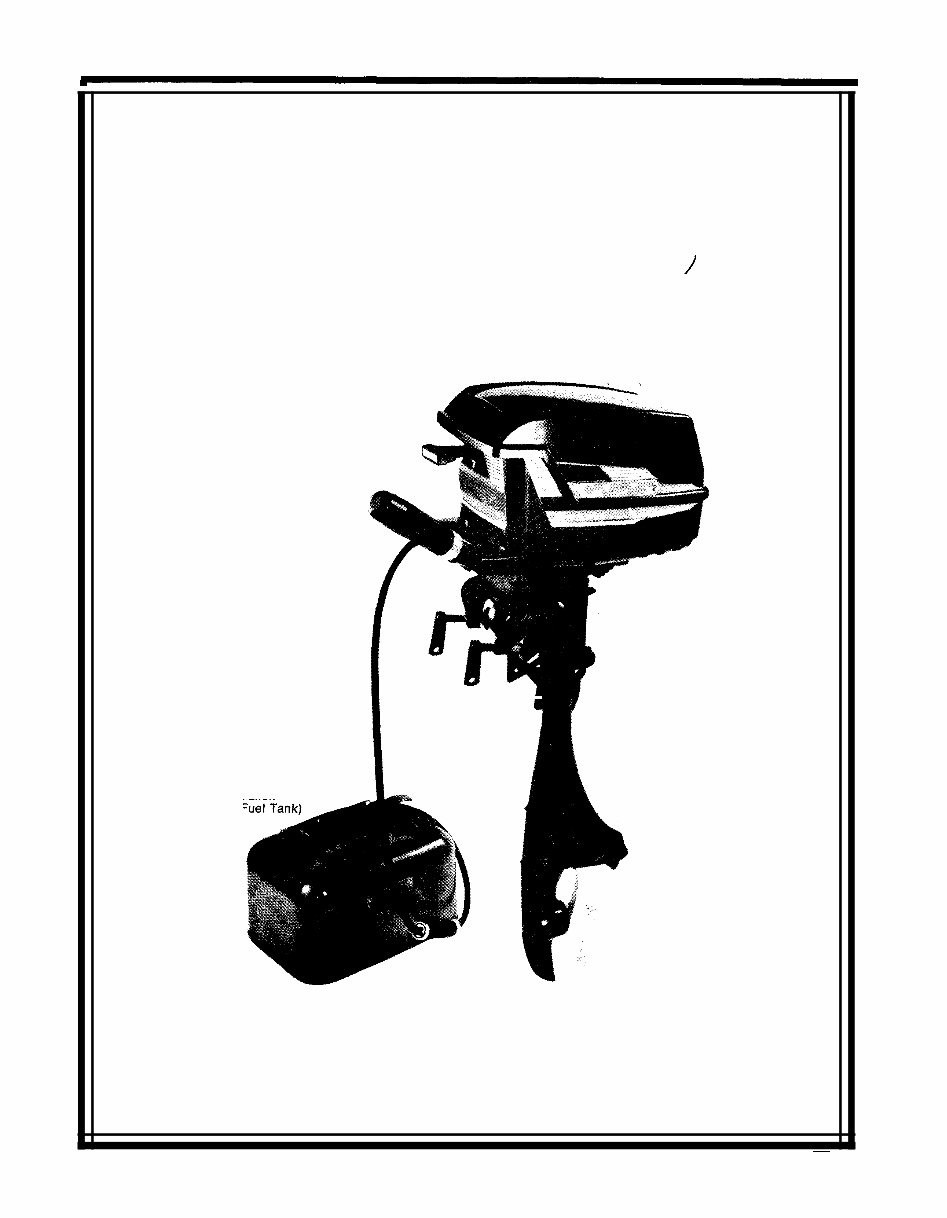
OWNERS MANUAL AND PARTS LIST FOR K - 700 OUTBOARD MOTOR PART NO. 137-596 AI R - COOLED MODEL K-700 (With 3 Gallon Remote I Manufactured by 7 - HP CLINTON ENGINES CORPORATION MAQUOKETA, IOWA orm No. 08 - 2134 PRINTED IN U.S.A.
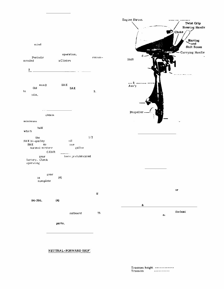
INTRODUCTION You have now invested in an Air Cooled Outboard Motor which has been engineered and built to the high- est of quality standards. Many hours of enjoyment are before you in boating pleasure. Read this Owner's Guide thoroughly before oper - ating the motor. The instructions are concise and com- plete in operation and recommendations to assure best in care and performance. As you read the instructions, keep in that maximum performance an3 service depend on the owner or operator. May we suggest that you practice the step by step instructions to be certain you are familiar with each servicing will be required. It is that you consult Service Center when service is required. CYCLE FUEL MIXTURE INSTRUCTIONS Use a good grade of regular gasoline. Do not use non- leaded gasoline. The use of premium gasolines will shorten spark plug life. In a clean container thoroughly ounces of high quality Outboard Motor (or its equivalent) of 30 or 40 viscosity one gallon of gasoline. Do not use D. M. 'or D. rated For best results strain mixed fuel through a fine screened funnel when filling gasoline tank. See Break- In Period instructions for the first tank full of gasoline. BREAK-IN PERIOD In order to maximum efficiency and service from your Outboard Motor it is recommended that a of five (5) hours Break- In Period be adhered to. During this period it is recommended the engine be run at throttle for a period of one hour, after it is permissible to increase engine speed gradually to full throttle. For first five (5) hours running, mix pint outboard motor (or its equivalent) of 30 or viscosity oil to gallon of gasoline. Use of 3 ounces per thereafter. The housing has at the HOUSING lubricant a: leas: every twenty (20) hours as follows: 1. With outboard lower column up, remove pro - peller and housing cap. NOTE: Gear housing cap retained by screws. Fill gear housing cavity with Clinton part number 951-247 grease. Replace gear housing cap, making sure that gas - ket between cap and housing is not damaged. gasket is damaged replace with gasket number Tighten cap screws securely and in- stall propeller. Always remove old lubricant and replenish with new lubricant at the end of the season or hours of usage. This is important, as it removes any water from the gear housing and prevents possible corrosion to internal 2. 3. TWIST GRIP SPEED CONTROL Turning the twist grip handle advances the throttle and spark. Zones for starting and shifting the motor are clearly indicated on the handle, NEUTRAL-FORWARD SHIFT A clutch is provided to allow starting the engine in neutral. A limiter is also provided to allow shifting only at safe RPM. Do not force the shift lever at any time. Placing the twist grip in the shift zone (low rpm) will allow the shift handle to be moved easily. 1 Starter Handle Neutral - Forwar Fuel Inlet Adapter - Clamp Screws Steering Adjustment Screws Stern Bracket Column Muffler Exhaust Cap Gear Housing STEERING ADJUSTMENTS The steering adjustment is controlled by a spring - mounted friction clamp located in the Swivel Bracket Cap. Turning the nuts located on each side of the cap will increase or decrease the steering tension. This device is designed to hold the motor on course at any speed, but if it is noticed that the boat wanders when not controlled by the operator, adjust the friction clamp by tightening the adjusting nuts. WATER PUMP Although the outboard has an air cooled engine, a water pump is provided to cool the column and con- dense exhaust gases. When the pump is working prop- erly a fine spray of water will come out of the small holes on rear of the column just below the reverse lug. If the water inlet holes are plugged the pump should fail, stop at once and correct the source of trouble. Do not run the outboard out of water for more than one minute as this may damage the water pump. INSTALLING ADJUSTING OUTBOARD T O BOAT 1. Mount the motor onthecenter of stern board. Secure the c l a p screws, tighten clamp screws by hand. Do not use a wrench or other tools. To adjust the motor to the proper position, loosen wing nut located on carriage bolt in stern bracket. Move to an angle enough to allow the outboard column to enter the water with the propeller at a right angle to the water surface when underway. With proper adjustment, tighten the wing nut securely. Should the motor race or over - load when making sharp turn, readjust the angle one notch downward. To obtain the best performance from your outboard, the following boat transom speci - fications are recommended. 15 inches angle 12 to 15 degrees 2. 3. 4. ----
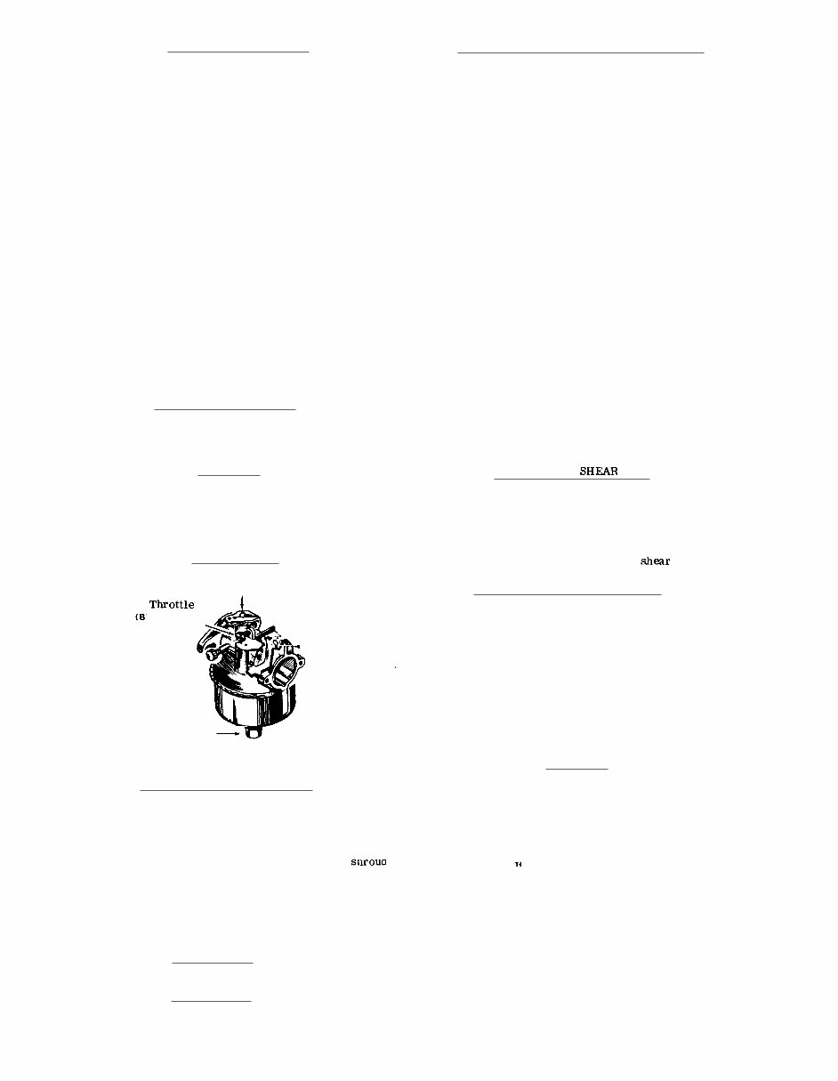
STARTING PROCEDURE To start the engine follow these steps: 1. 2. Insert fuel coupling into fuel pump inlet adapter located on the underside front carrying handle. Open air vent on tank. Since fuel is supplied to the carb - uretor by means of the fuel pump, it is necessary to prime the fuel system. The primer is located between the remote tank and the fuel pump. To operate primer pump, squeeze by hand. Upon squeezing the primer, fuel is forced into the fuel line and carburetor. When sufficient fuel is in the system, it will be noted that it becomes more difficult to squeeze primer. This is your signal that sufficient fuel is in the system. Turn throttle control twist grip to slow position. Move shift handle to its rear or neutral position. Turn throttle control twist grip toward high speed until it stops. Pull choke knob out to full limit. Pull recoil rope until engine starts. After engine starts push choke knob in about halfway and leave in this position until engine warms up suffi- ciently then push choke knob all the way in. When ready to go forward, turn twist grip to slow position and pull shift lever forward. 3. 4. 5. 6. 7. 8. 9. REMEMBER: Do not accelerate engine to full speed until completing "Br eak- In" period. STOPPING PROCEDURE To stop outboard turn twist grip throttle to slow position and pull choke knob out full limit. Tighten air vent on fuel tank if outboard is not going to be run for a period of time. FLOODING Flooding is usually caused by over choking the outboard. If flooding occurs see that the choke is all way open and that the throttle twist grip is at START. Continue to pull the starter handle until the outboard starts. It may be necessary to remove the spark plug and dry the electrodes. CARBURETOR Throttle Shaft ? Choke / Lever stop, Screw Idle (c) Adjustment - __ Fuel Inlet Scr ew power (A) Adjustment Screw CARBURETOR ADJUSTMENT CARBURETOR ADJUSTMENT CONTINUED to warm up. To adjust carburetor power adjustment screw (A) move throttle control lever to fast position and turn (A) power adjustment screw clockwise until engine speed drops off. Then turn counter - clockwise 1/4 turn. If needle is open too far, engine exhaust will be heavy and speed will drop off. To adjust (C) idle adjustment screw, move throttle control lever to slow position, Adjust (B) throttle shaft stop screw to keep engine operating at low speed. Stap screw (B) sets minimum speed. Turn (C) idle adjustment screw clockwise very slowly and continue closing as long as engine sound im - proves and speed increases. In some cases idle needle may need to be opened counter - clockwise to secure desired results. Throttle shaft stop screw (B) will usually require a change to set minimum speed as desired. Normal idle speed is 700 to 800 revolutions per minute. Check engine acceleration from slow to fast op- eration, It may be necessary to open (C) idle adjustment screw counter - clockwise 1/8 turn to secure best acceleration from slow to fast speeds. Should engine backfire or pop when throttle con- trol lever is moved to slow position, the idle mixture is too lean. To correct this turn the (C) idle adjustment screw counter - clockwise until backfiring or popping is eliminated when throttle control lever is moved to slow position. 4. 5. 6. 7. PROPELLER PIN The soft " safety" pin shears off when an obstruction is struck at high speed, thus protecting the gears, shafts from. damage. When shear pin is broken the engine will continue to run, however, the propeller will not be rotating. To re - pair, shut off motor, remove propeller cotter pin and nut. Slip off propeller and replace with new pin. Extra shear pins and cotter pin are located on mounting bracket. MAGNETO & IGNITION SYSTEM Inspect spark plug every fifty hours of operation. If engine fails to start or hard to start, check gasoline supply, carburetion and spark plug. To test magneto for spark, re - move high tension wire from spark plug and hold about 1/8" from any metal part of motor and pull starter cord. If a spark bridges the gap the magneto is in good operating con- dition. If no spark, have the condenser and coil checked at an authorized Clinton Service Center. The setting for breaker points is .020 and spark plug gap is .025. The correct spark plug is a Champion Type CJ8 or equivalent. STORAGE When removing the motor from the boat raise the out - The carburetor is adjusted at the factory. It should not be board in upward direction until the propeller clears the necessary to readjust it until the engine is well broken in at stern b o a r d. H o ld the motor upr i g ht l ong enoug h t o a ll ow which time you may want to adjust. To do this Or to verify the all water to drain from the exhaust ports in the lower end original adjustments proceed as follows: Remove by o f the column. the motor is operated in salt water thor - turning shroud latch lever at rear of the lower shroud counter - oug hl y rinse th e lower unit with fresh water or run out - board in a fresh water tank. clockwise to release, then lift shroud up and forward. Idle adjustment screw may be adjusted with a screw driver To store your outboard drain all water from lower by removing the idle adjustment plug that is located about column and drain gas line and carburetor. Place motor midway in the middle shroud. on its side, remove spark plug and pour about 1/4 cup of Turn (A) power adjustment screw clockwise until oil into spark plug hole. Pull starter rope several times closed. Do Not Force. Then open counter - clock- to rotate the crankshaft then replace spark plug. Fill wise at least 2- 1/2 turns. gear housing with grease as directed. Store in uprlght Turn (C) idle adjustment screw clockwise until position. When starting a new season always use fresh closed. Do Not Force. Then open counter - clock- gasoline. Last years gasoline may have varnish deposits wise at least 1- 1/2 turns from closed position. that will plug the carburetor jets thus requiring a carb - Start engine. A!low a short period of time for engine uretor overhaul. 1. 9. 3. - 2 -
ALL CLINTON PRODUCTS ARE WARRANTED. CLINTON ENGINES CORPORATION will replace to the original owner free of charge any part or parts shown on examination by a Clinton Authorized Service Account or Clinton factory to be defective in material and/or workmanship. This war - ranty does not cover normal wear nor apply in the event of damage or con - dition resulting from accident, abuse, misuse, unauthorized repair, fail- ure to mix fuel - oil ratio or failure to follow instructions in the Owner's Guide. The warranty will apply and becomes effective from date of purchase. This warranty supersedes all previous warranty written, expressed or im - plied. Clinton Engines shall be in no way liable for incidental or consequent - ial damage. All transportation charges on parts or assemblies submitted for re - placement under this warranty must be borne by the purchaser. Outboard Warranty Period two years CLINTON ENGINES CORPORATION Iowa FOR SERVICE SEE THE YELLOW PAGES. LOOK FOR "CLINTON" UNDER ENGINES COOLED. PROCEDURE SALESMAN OR DEALER: Please fill out this warranty form to insure that your customer will receive warranty service if needed. Owner's Name City Stat e County Street Address or No. Outboard Model No. (Copy No. from Outboard name plate) Outboard Serial No, Date Purchased Purchased From City Stat e CUSTOMER: Should warranty service be required, present this completed warranty form your Authorized Clinton Service Account along with outboard
The Clinton Outboard K700 7 HP manual is an essential resource for anyone involved in the repair and maintenance of outboard engines. This manual provides detailed information on the operation, maintenance, and repair of the Clinton K700 7 HP outboard engine. Whether you are a professional mechanic or a DIY enthusiast, this manual offers valuable insights into the inner workings of the engine, making it easier to diagnose and fix issues.
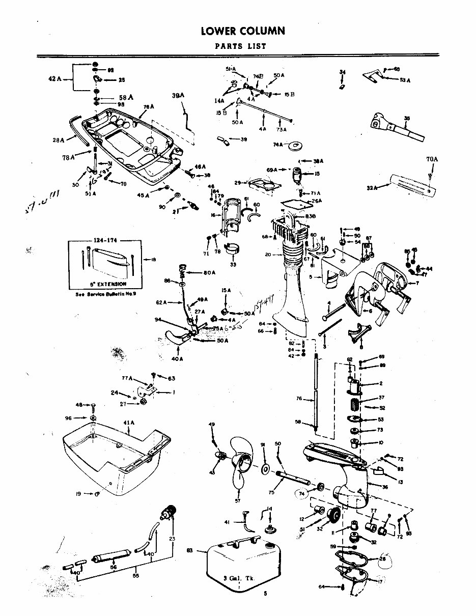
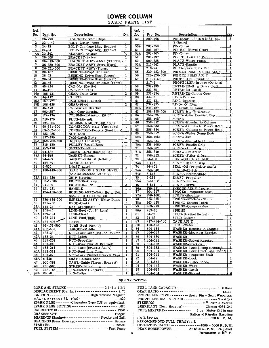
Additionally, the manual includes comprehensive parts diagrams and lists, allowing you to easily identify and order the necessary components for your Clinton K700 7 HP outboard engine. With clear and concise instructions, this manual is a valuable tool for ensuring the smooth operation and longevity of your outboard engine.