

Raymarine C80 Service Manual
What's Included?
Fast Download Speeds
Online & Offline Access
Access PDF Contents & Bookmarks
Full Search Facility
Print one or all pages of your manual
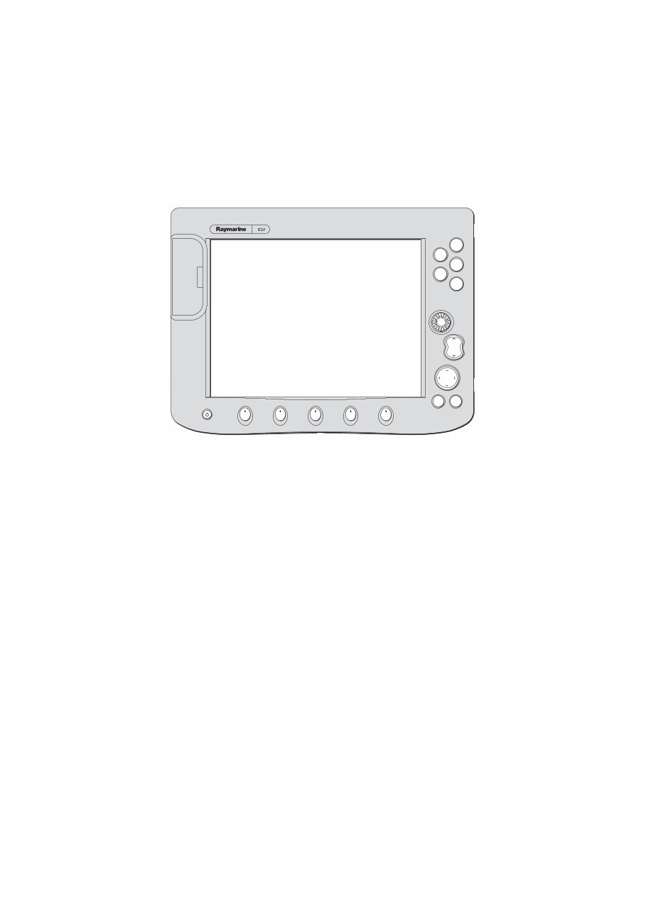
C80 Display
Service Pack
Document number: 83173_1
June 2004
RANGE
CANCEL OK
PAGE
ACTIVE
WPTS/
MOB
MENU
DATA
IN
OUT
D6572-2


C80 Display Service Pack 1
Introduction
Safety notices
WARNING:Electrical safety
Make sure the power supply is switched off before making any
electrical connections.
WARNING:Product servicing
The C-Series Display must be serviced in accordance with the
Raymarine instructions provided. Failure to do so could result in
poor product performance, personal injury and/or damage to the
boat.
WARNING:Electromagnetic energy
The radar scanner transmits electromagnetic energy. Ensure that
the scanner has been installed according to the recommendations
given in the relevant scanner handbook.
WARNING:Fishfinder sounder module
Removing the transducer cable from the rear of the fishfinder
sounder module whilst it is switched on can cause sparks. Only
remove the transducer cable after power has been switched off.
Ensure that the sounder module is mounted where it is well
ventilated and in an area free from flammable vapors.
CAUTION: Electrostatic Discharge
The C-Series Display contains electrostatic sensitive components.
Always observe the appropriate precautions when handling, shipping
and storing this product. Failure to do this could result in permanent
damage to the equipment.
CAUTION: CompactFlash Cards
Removing the CompactFlash card whilst information is being written to
or read from it may cause damage to the card and loss of all data. A
warning on the display indicates when the car d is being accessed.
CAUTION: Card Damage
DO NOT use a metallic instrument such as a screwdriver or pliers to help
you remove a card, as doing this can cause irreparable damage.
CAUTION: Global Positioning System Antenna
Do not connect or disconnect the GPS antenna from the display unit
whilst power is switched on. Doing this may result in irreparable
damage.

2 C80 Display Service Pack
Contents
This service pack contains the following information:
• Diagrams - PCBs and circuit diagrams (page 3)
• Spares List (page 42)
• Exploded view (Page 43)
• Disassembly and reassembly instructions (page 45)
• Systems diagnostics (page 49)

C80 Display Service Pack 3
Chapter 1:Diagrams
This chapter contains all the circuit and PCB diagrams for the C80 Display:
Note: These circuit diagrams are typical for a C80 Display but may be subject to revision. If you have any queries
relating to the version required for a particular C-Series Display, please contact the Raymarine Service Depart-
ment.
CPU/CCFL (from page 4)
• Surface mount PCB - topside and underside
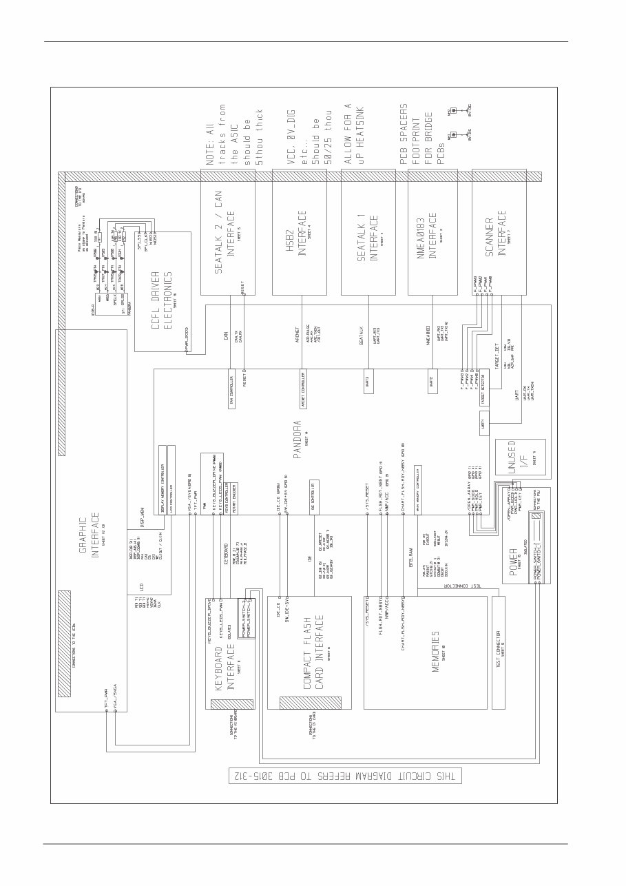
• CPU/CCFL Overview:
• NMEA0183 Interface
• SeaTalk 1 Interface
• HSB2 Interface
• SeaTalk 2/CAN Interface
• Compact Flash Card Interface
• Scanner Interface
• Keyboard Interface
• Test Connection
• Memories
• Unused I/F
• Graphic Interface
• Graphic Interface - TFT Connections
• Pandora
• Power
• CCFL Driver Electronics
PSU/Connector (from page 22)
• Surface Mount - components and converntional components
• PSU/Connector Overview:
• Power Conditioning
• Scanner
• HSB
• SeaTalk 1
• SeaTalk 2
• NMEA
• Protection
• PSU
Keyboard (from page 33)
• Keyboard PCB
• Keyboard Overview:
• Matrix
• LEDs Array
• Buzzer Circuitry
• Keyboard Flexi
Jockey board (from page 39)
• Jockey PCB
• Jockey Circuit diagram
• Jockey Flexi
4 C80 Display Service Pack
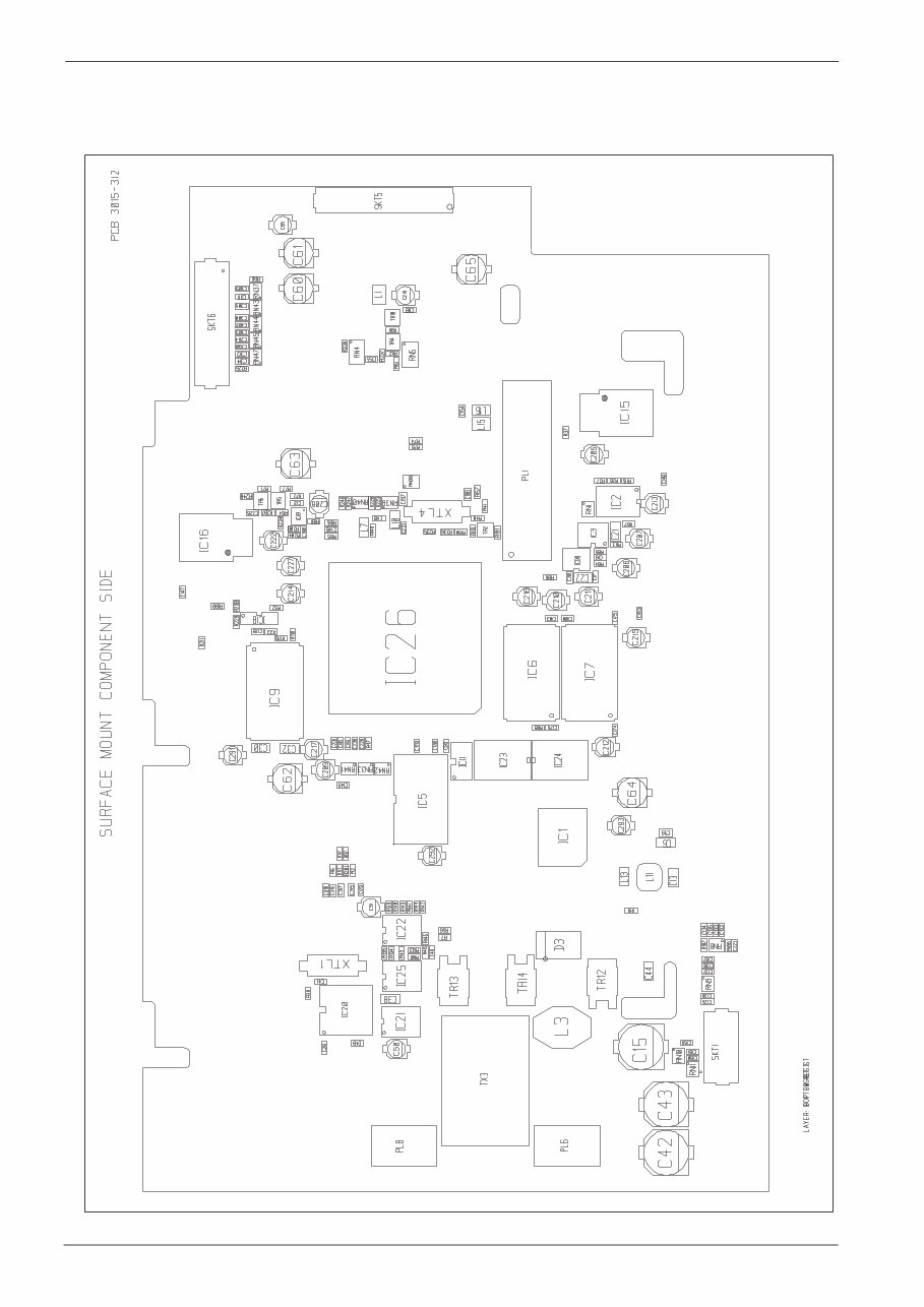
1.1 CPU/CCFL
Figure 1-1: CPU Surface Mount (Topside)
D7125-1 (from Drawing No. 4579-001D)
C80 Display Service Pack 5
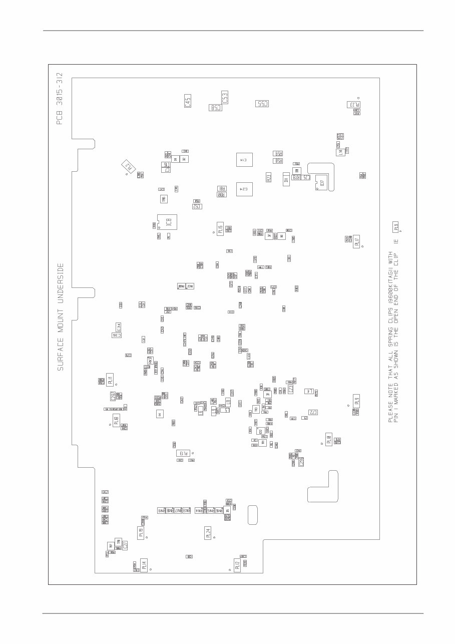
Figure 1-2: CPU Surface Mount (Underside)
D7126-1 (from Drawing No. 4579-001D)
6 C80 Display Service Pack
Figure 1-3: CPU/CCFL Overview
D7082-1 (from Drawing No. 4579-005H)
C80 Display Service Pack 7
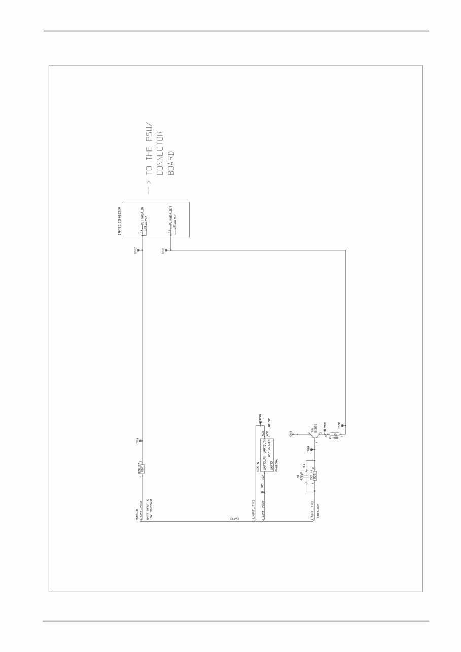
Figure 1-4: NMEA 0183 Interface (sheet 2)
D7115-1 (from Drawing No. 4579-005H)
8 C80 Display Service Pack
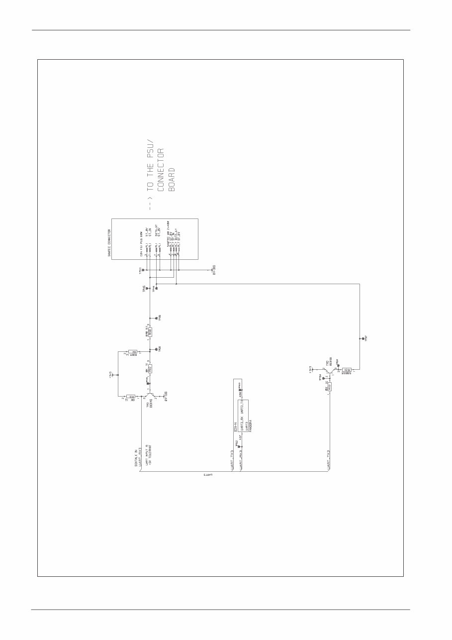
Figure 1-5: SeaTalk 1 Interface (sheet 3)
D7087-1 (from Drawing No. 4579-005H)
You're Reading a Preview
What's Included?
Fast Download Speeds
Online & Offline Access
Access PDF Contents & Bookmarks
Full Search Facility
Print one or all pages of your manual
$31.99
$41.99
Viewed 19 Times Today


Secure transaction
What's Included?
Fast Download Speeds
Online & Offline Access
Access PDF Contents & Bookmarks
Full Search Facility
Print one or all pages of your manual
$31.99
$41.99
The Raymarine C80 Service Manual provides essential information for professional mechanics and DIY enthusiasts. It includes diagrams for PCBs and circuit diagrams, a spares list, an exploded view, disassembly and reassembly instructions, as well as systems diagnostics. This manual is available in .PDF format.


