

YAMAHA WAVERUNNER 3 III WRA700 Workshop Repair Manual 1994-1997
What's Included?
Fast Download Speeds
Online & Offline Access
Access PDF Contents & Bookmarks
Full Search Facility
Print one or all pages of your manual

This service manuals covers the 1990-1997 650/700 Waverunner III Series.
Please understand that this is an older manual, some pictures may be darker than most of my
manuals.
Some models may need supplemental manuals which have blue titles . Use the base
manual for everything not contained in the supplement if your model or year requires
a supplement.
This manual is fully searchable, just hold down the control key and the F key to
search on any word.
If you bought this manual from any other seller, they are reselling my work.
Please leave them negative feedback & email me at sales@midwestmanuals.com .
Our goal is to be one of the BEST sellers on eBay and the internet by providing you with
the BEST customer service and the BEST manuals on the market.
Thank you for choosing us.
If you bought this from any other seller, please email me at sales@midwestmanuals.com
al s@
WWW. I
CD
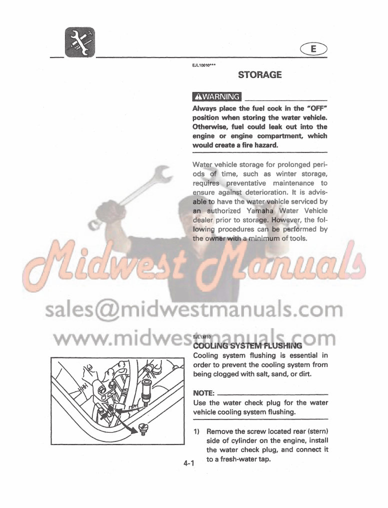
EJL 10010'"
STORAGE
Always place the fuel cock in the "OFF"
position when storing the water vehicle.
Otherwise, fuel could leak out into the
engine or engine compartment, which
would create a fire hazard.
Water vehicle storage for prolonged peri-
ods of time, such as winter storage,
requi res preventative maintenance to
ensure against deterioration. It is advis-
able to have the water vehicle serviced by
an authorized Yamaha Water Vehicle
dealer prior to storage. However, the fol-
l owing procedures ca n be performed by
the owner with a minimum of tools.
o
Cooling system flushing is essential in
order to prevent the cooling system from
being clogged with salt, sand, or dirt.
NOTE: ____________________ ___
Use the water check plug for the water
vehicle cooling system flushing.
4-1
1) Remove the screw located rear (stern)
side of cylinder on the engine. install
the water check plug, and connect it
to a fresh-water tap.
CD
2) Start the engine, then immediately
turn on the water supply.
Nevel' turn on the water before starting
the engine. The water could flow back
through the muffler into the crankcase
causing severe engine damage.
Be sure to turn on the water immediately
after starting the engine to prevent
engine overheating.
3) Run the engine at a fast idle for 10-15
minutes.
4) Turn off the water supply and force
the remaining water out of the cool-
ing system by quickly opening and
closing the throttle several times for
10 to 15 seconds.
Never have the water on when the
engine is not running. The water could
flow back through the muffler into the
crankcase causing severe engine damage.
Do not run the engine for more than 15
seconds after the water supply has been
turned off to avoid engine overheating.
5) After stopping the engine. remove the
water check plug and replace the
screw.
4-2
CD
EJL 17113'
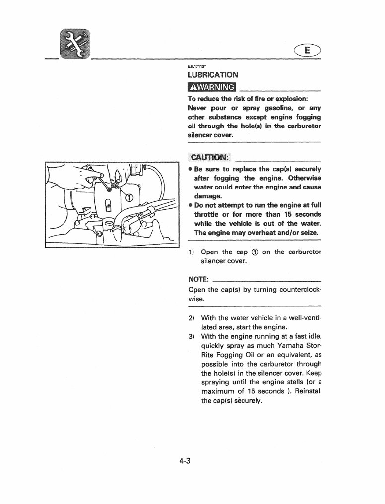
LUBRICATION
To reduce the risk of fire or explosion:
Never pOUI" or spray gasoline, or any
other substance except engine fogging
oil through the hole(sJ in the carburetor
silencer cover .
• Be sure to replace the cap!sl securely
after fogging the engine. Otherwise
water could entel' the engine and cause
damage.
• Do not attempt to run the engine at full
throttle or for more than 15 seconds
while the vehicle is out of the water.
The engine may overheat andlor seize.
1) Open the cap CD on the carburetor
silencer cover.
NOTE:
Open the cap(s) by turning counterciock-
wise.
2) With the water vehicle in a well-venti-
lated area, start the engine.
3) With the engine running at a fast idle,
quickly spray as much Yamaha Stor-
Rite Fogging Oil or an equivalent, as
possible into the carburetor through
the hole(s) in the silencer cover. Keep
spraying until the engine stalls (or a
maximum of 15 seconds ). Reinstall
the cap(s) securely.
4-3
CD
4) Remove the spark plugs and pour
approximately one tablespoon of oil
into each cylinder.
5) Grease the spark plug threads and
reinstall the spark plugs.
6) Lubricate all cables such as the throt-
tle, choke, and steering cables.
NOTE: ____________________ __
Use a Yamaha Power Cable Luber and
Yamaha Lube-Zall to pressure lubricate
the cables and purge out any moisture
between the inner and outer cables.
7) Grease the areas of the water vehicle
specified in "Grease Points" in the
ADJUSTMENT AND MAINTENANCE
section.
EJL 15011
fUEL SYSTEM
1) Top off the fuel tank with fresh fuel/oil
mixture and add one ounce of Yama-
ha Fuel Stabilizer and Conditioner to
each gallon of fuel.
NOTE: _______________________
Use of Yamaha Fuel Stabilizer and Condi-
tioner eliminates the need to drain the
fuel system. Consult your Yamaha dealer
or other qualified mechanic if the fuel sys-
tem is to be drained instead.
4-4
CD
JL20010*""*·
BAITERY
1) When the machine is not to be used
for a month or more, remove the bat-
tery and store it in a cool, dark place.
Clean the battery's casing and termi-
nals using a mixture of baking soda
and water (one tbsp. of baking soda
to one cup of water). Apply dielectric
grease or petroleum jelly to the bat-
tery terminals and to all exposed con-
nectors.
2) If the battery is to be stored for a
longer period, check the specific grav-
ity of the fluid at least once a month
and recharge the battery if it gets too
low.
Specific gravity: 1.28 at 20°C (68°F)
EJL22011'
CLEANING
1) Wash down the hull, handlebars, and
drive unit with fresh water.
2) Rinse the engine and bilge area with
fresh water. Drain off all water and
wipe up remaining moisture with
clean, dry rags.
3) Spray the engine's exterior with
Yamaha Silicone Protectant and
lubricant.
4) Wax the hull with a non-abrasive wax
such as Yamaha Silicone Wax.
5) Wipe all vinyl and rubber compo-
nents, such as the seat and engine
compartment seals, with a vinyl pro-
tectant such as Yamaha Protectant.
4-5
If you bought this from any other seller, please email me at sales@midwestmanuals.com
CHAPTER 1
GENERAL INFORMATION
HOW TO USE THIS MANUAL .......................................................................... 1-1
MANUAL FORMAT ....................................................................................... 1-1
THE ILLUSTRATIONS .................................................................................. 1-1
REFERENCES ............................................................................................... 1-1
WARNINGS, CAUTIONS AND NOTES ...................................................... 1-1
SYMBOLS ....................................................................................................... 1-2
IDENTIFICATION NUMBERS ............................................................................ 1-3
HULL IDENTIFICATION NUMBER (H.I.N.) ................................................ 1-3
PRIMARY I.D. NUMBER ............................................................................... 1-3
ENGINE SERIAL NUMBER .......................................................................... 1-3
SAFETY WHILE WORKING .............................................................................. 1-4
FIRE PREVENTION ...................................................................................... 1-4
VENTILATION ................................................................................................ 1-4
SELF-PROTECTION ...................................................................................... 1-4
OILS, GREASES AND SEALING FLUIDS .................................................. 1-4
GOOD WORKING PRACTICES ................................................................... 1-4
DISASSEMBLY AND ASSEMBLY ............................................................... 1-4
SPECIAL TOOLS ................................................................................................ 1-5
SPECIAL TOOLS FOR TUNE-UP ............................................................... 1-5
SPECIAL TOOLS FOR POWER UNIT SERVICE ...................................... 1-6
SPECIAL TOOLS FOR DRIVE UNIT SERVICE ........................................ 1-6
SEALING AGENTS AND LUBRICANTS ......................................................... 1-9
CHAPTER 2
SPECIFICATIONS
GENERAL SPECIFICATIONS ........................................................................... 2-1
MAINTENANCE SPECIFICATIONS .................................................................. 2-2
TORQUE SPECIFICATIONS .............................................................................. 2-3
GENERAL TORQUE SPECIFICATION ............................................................ 2-4
If you bought this from any other seller, please email me at sales@midwestmanuals.com
CHAPTER 3
GENERAL SERVICE
PERIODIC MAINTENANCE ............................................................................... 3-1
MAINTENANCE INTERVAL CHART ........................................................... 3-1
TROLLING SPEED ADJUSTMENT .................................................................. 3-2
FUEL SYSTEM INSPECTION ............................................................................ 3-3
FUEL FILTER ................................................................................................. 3-3
CHECK VALVE .............................................................................................. 3-4
FUEL FILLER ................................................................................................. 3-4
OIL INJECTION SYSTEM INSPECTION ......................................................... 3-5
OIL FILTER .................................................................................................... 3-5
CHECK VALVE .............................................................................................. 3-5
THROTTLE LEVER ADJUSTMENT ................................................................. 3-6
CHOKE CABLE ADJUSTMENT ........................................................................ 3-6
REVERSE SYSTEM INSPECTION AND ADJUSTMENT .............................. 3-7
STEERING SYSTEM INSPECTION AND ADJUSTMENT ............................. 3-8
PIVOT SHAFT BEARING ............................................................................. 3-8
STEERING CABLE ........................................................................................ 3-8
IMPELLER INSPECTION ................................................................................ 3-10
RUBBER COUPLING ................................................................................. 3-11
ELECTRICAL SYSTEM INSPECTION .......................................................... 3-12
ELECTRICAL WIRE .................................................................................... 3-12
STARTER SWITCH/STOP SWITCH ........................................................ 3-12
BATTERY ..................................................................................................... 3-13
SPARK PLUG .............................................................................................. 3-15
COMPRESSION PRESSURE INSPECTION ........................................... 3-16
HULL AND HOOD INSPECTION ................................................................... 3-17
SEAL RUBBER ........................................................................................... 3-17
BILGE STRAINER ...................................................................................... 3-17
DRAIN PLUG ............................................................................................... 3-17
GREASING POINTS ......................................................................................... 3-18
If you bought this from any other seller, please email me at sales@midwestmanuals.com
CHAPTER 4
FUEL SYSTEM
FUEL SYSTEM DIAGRAM ................................................................................. 4-1
FUEL SYSTEM ..................................................................................................... 4-2
PREPARATION FOR REMOVAL ................................................................ 4-2
EXPLODED DIAGRAM ................................................................................. 4-2
FUEL SYSTEM INSPECTION ...................................................................... 4-3
FUEL SYSTEM INSTALLATION .................................................................. 4-3
CARBURETOR .................................................................................................... 4-4
PREPARATION FOR REMOVAL ................................................................ 4-4
EXPLODED DIAGRAM ................................................................................. 4-4
CLEAN AND INSPECTION ........................................................................... 4-5
ASSEMBLY ..................................................................................................... 4-7
INSTALLATION AND ADJUSTMENT ......................................................... 4-8
OIL INJECTION SYSTEM DIAGRAM .............................................................. 4-9
OIL INJECTION SYSTEM .............................. ................................................. 4-10
EXPLODED DIAGRAM .............................................................................. 4-10
OIL INJECTION SYSTEM INSPECTION ................................................. 4-11
OIL INJECTION SYSTEM INSTALLATION ............................................. 4-11
CHAPTER 5
POWER UNIT
ENGINE UNIT ...................................................................................................... 5-1
PREPARATION FOR REMOVAL ................................................................ 5-1
REMOVAL AND DISCONNECTION ............................................................ 5-1
EXPLODED DIAGRAM ................................................................................. 5-2
INSPECTION AND REPAIR .............................................................................. 5-3
CYLINDER .HEAD .......................................................................................... 5-3
CYLINDER BLOCK ........................................................................................ 5-3
PISTON ........................................................................................................... 5-4
PISTON RINGS .............................................................................................. 5-6
PISTON PIN AND BEARING ....................................................................... 5-6
CRANKSHAFT ............................................................................................... 5-7
CRAN KCASE .................................................................................................. 5-8
REED VALVE ................................................................................................. 5-8
CRANK MAIN BEARING .............................................................................. 5-9
You're Reading a Preview
What's Included?
Fast Download Speeds
Online & Offline Access
Access PDF Contents & Bookmarks
Full Search Facility
Print one or all pages of your manual
$35.99
Viewed 21 Times Today


Secure transaction
What's Included?
Fast Download Speeds
Online & Offline Access
Access PDF Contents & Bookmarks
Full Search Facility
Print one or all pages of your manual
$35.99
This workshop manual for the Yamaha Waverunner 3 III WRA700 covers the years 1994-1997. It contains comprehensive repair, maintenance, and rebuilding information suitable for both professional technicians and DIY enthusiasts.
- Includes detailed repair procedures from A-Z
- High-quality photos, illustrations, and diagrams
- Compatible with Microsoft Windows 95, 98, 98SE, 2000, NT, ME, XP, Vista, and Windows 7, as well as all Mac computers
With this workshop manual, you can easily access and print the necessary repair procedures without requiring advanced computer skills. Say goodbye to cumbersome and worn-out manuals, and save significantly on service and repair costs.


