HOW TO USE THIS MANUAL MANUAL FORMAT All of the procedures in this manual are organized in a sequential, step-by-step format. The information has been compiled to provide the mechanic with an easy to read, handy refer- ence that contains comprehensive explanations of all disassembly, repair, assembly, and inspection operations. In this revised format, the condition of a faulty component will precede an arrow symbol and the course of action required will follow the symbol, e.g., • Bearings Pitting/scratches ~ Replace. To assist you in finding your way through this manual, the section title and major heading is given at the top of every page. ILLUSTRATIONS The illustrations within this service manual represent all of the designated models. CROSS REFERENCES The cross references have been kept to a minimum. Cross references will direct you to the appropriate section or chapter.
IMPORTANT INFORMATION In this Service Manual particularly important information is distinguished in the following ways. it The Safety Alert Symbol means ATTENTION! BECOME ALERT! YOUR SAFETY IS INVOLVED! A WARNING Failure to follow WARNING instructions could result in severe injury or death to the machine operator, a bystander, or a person inspecting or repairing the water vehicle. A CAUTION indicates special precautions that must be taken to avoid damage to the water vehicle. N9TE: __________________________________________________ __ A NOTE provides key information to make procedures easier or clearer. IMPORTANT: ________________________________________________ ___ Thi~ part has been subjected to change of specification during production. \
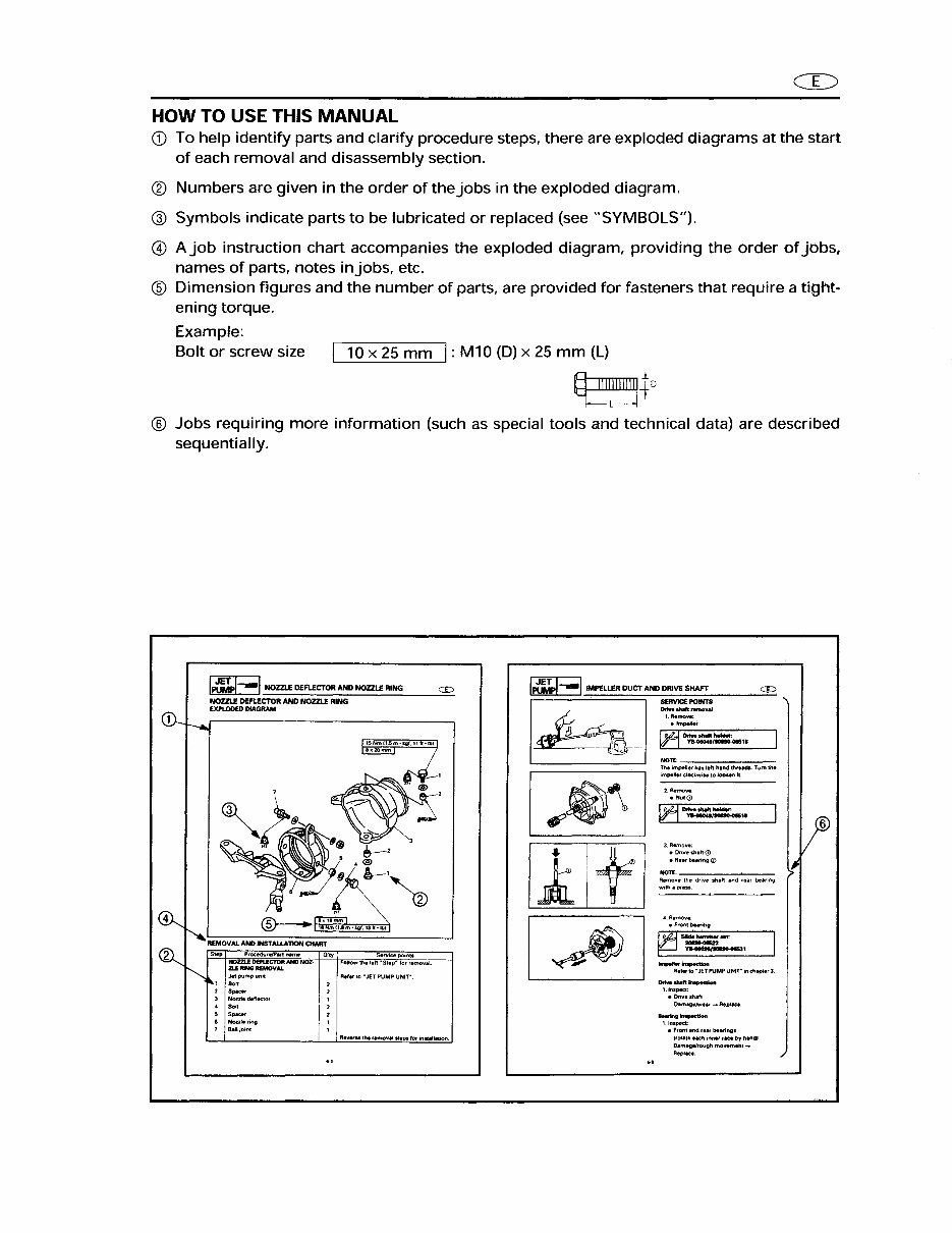
CD HOW TO USE THIS MANUAL CD To help identify parts and clarify procedure steps, there are exploded diagrams at the start of each removal and disassembly section. ® Numbers are given in the order ofthejobs in the exploded diagram. @ Symbols indicate parts to be lubricated or replaced (see "SYMBOLS"). @ Ajob instruction chart accompanies the exploded diagram, providing the order of jobs, names of parts, notes injobs, etc. ® Dimension figures and the number of parts, are provided for fasteners that require a tight- ening torque. Example: Bolt or screw size 10 x 25 mm I: M10 (D) x 25 mm (L) ~ IIIIIIIIIIII+D ~L----I ® Jobs requiring more information (such as special tools and technical data) are described sequentially. I~--I NOZZLE DEFLECTOR AND NOZZLE RING = NOZZLE DEFLECTOR AND NOZZLE RING EXPLODED DIAGRAM CD- r-. 15Hm!1.5",·kgf,llft-1b1 ~ J, n, <i> 7 2 , @, ~ ~ ~X: i!J Ir-' , 'm ~ I'-. ~~m'kgf.1Jtt'lbl REMOVAl ANO INSTAllATION CHART ~ Step Procedure/Part name Q'~ Servie. point. NOZZLE DEFL.ECTOR AND NOl- FOllow th, 11ft ~SIlP- for ...",0 ... ,1 ~ lLElltNQREMOVAL Jet pump unit Ref'r 10 • JET PUMP UNIT". , 00' 2 2 5~.r 2 3 Hozzll<HfleclM , . BoO 2 , S_ 2 . Nonllrin9 , 7 Balljoinl , R • .....,. , .... removal stlPS tor installl'ion. . , 1..tJMi.1--IIMPELLER DUCT AND DRIVE SHAFT = -- Ref., to • JET PUMP UNIT" ifI chapW 3 I. Inspect: • Orivesh.fI o.maogeJwllM"" Aeplace. ....... - 1.lnsped: • FtCu" and r"f lIoearing. 'roUlI. each ;""_ fKtl by h~dl o.mage/rough mowment .... Replace.
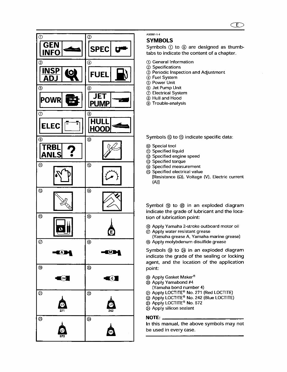
<D II~~~I ..... ·1 @ II:grl_1 ® IpOW~.1 (J) IELECIOI ® Il:~~ ? I ® ~ @) ~ @ [iID @ ~ @l ~ @ 1 a 271 @ 1 a 572 ® ISPECI ~ I @ IFUELI.i) I ® Ipt~pl- -I ® I~~~I .. I @) ~ ® §] @ ~ @ 1 m @ ~ ® C!I @ 1 a 242 @ 1 a CD A50001-1-4 SYMBOLS Symbols ill to ® are designed as thumb- tabs to indicate the content of a chapter. <D General Information ® Specifications @ Periodic Inspection and Adjustment @ Fuel System ® Power Unit ® Jet Pump Unit (J) Electrical System ® Hull and Hood ® Trouble-analysis Symbols @) to @) indicate specific data: @) Special tool ® Specified liquid ® Specified engine speed @) Specified torque @ Specified measurement @ Specified electrical value [Resistance (Q), Voltage (V), Electric current (A)) Symbol @ to @ in an exploded diagram indicate the grade of lubricant and the loca- tion of lubrication point: @ Apply Yamaha 2-stroke outboard motor oil @ Apply water resistant grease (Yamaha grease A, Yamaha marine grease) @ Apply mOlybdenum disulfide grease Symbols @> to @ in an exploded diagram indicate the grade of the sealing or locking agent, and the location of the application point: @l Apply Gasket Maker® ® Apply Yamabond #4 (Yamaha bond number 4) @ Apply LOCTITE® No. 271 (Red LOCTITE) @ Apply LOCTITE® No. 242 (Blue LOCTITE) @ Apply LOCTITE® No. 572 @ Apply silicon sealant NOTE: ________________________ _ In this manual, the above symbols may not be used in every case.
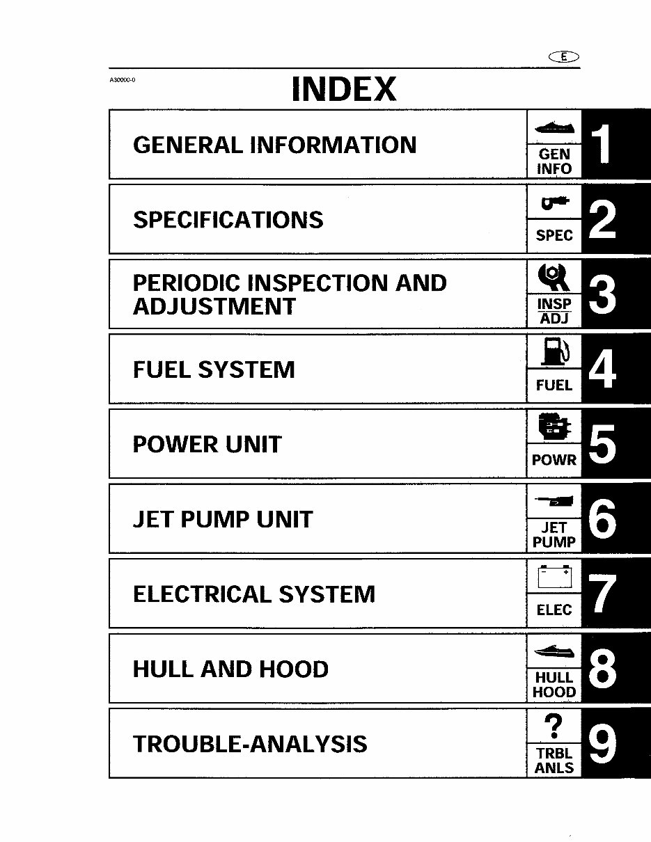
A30000-0 INDEX GENERAL INFORMATION SPECIFICATIONS PERIODIC INSPECTION AND ADJUSTMENT FUEL SYSTEM POWER UNIT JET PUMP UNIT ELECTRICAL SYSTEM , HULL AND HOOD TROUBLE-ANAL YSIS • r o ElEe
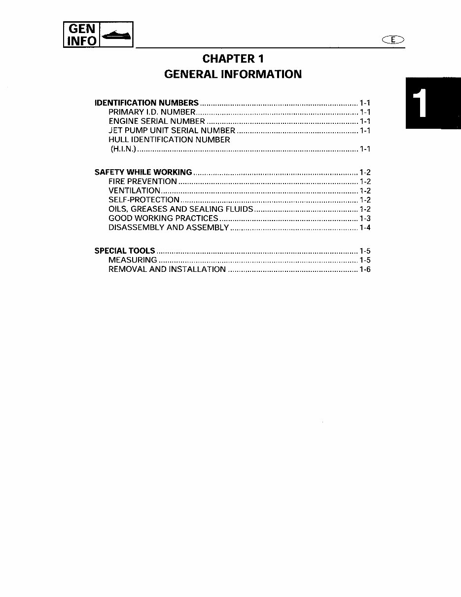
II~~~I • SI ________________ C~_E_:> CHAPTER 1 GENERAL INFORMATION IDENTIFICATION NUMBERS ....... .................................................................. 1-1 PRIMARY 1.0. NUMBER ........................................................................... 1-1 ENGINE SERIAL NUMBER ...................................................................... 1-1 JET PUMP UNIT SERIAL NUMBER ........................................................ 1-1 HULL IDENTIFICATION NUMBER (H.I.N.} ...................................................................................................... 1-1 SAFETY WHILE WORKING ............................................................................ 1-2 FIRE PREVENTION ................................................................................... 1-2 VENTILATION ........................................................................................... 1-2 SELF-PROTECTION .................................................................................. 1-2 OILS, GREASES AND SEALING FLUIDS ................................................ 1-2 GOOD WORKING PRACTICES ................................................................ 1-3 DISASSEMBLY AND ASSEMBLy ........................................................... 1-4 SPECIAL TOOLS ............................................................................................. 1-5 MEASURING ............................................................................................ 1-5 REMOVAL AND INSTALLATION ............................................................ 1-6 http://ReadManuals.com
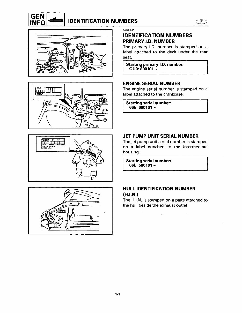
II~~~I .. ·1 IDENTIFICATION NUMBERS ffij [ffi]]1E2J If AMAHA MOTOR MANUfACruRlNG COAl' , OF AMERICA MADE IN U.S.A. 1-1 A60700-0' IDENTIFICATION NUMBERS PRIMARY 1.0. NUMBER The primary '-D. number is stamped on a label attached to the deck under the rear seat. Starting primary 1.0. number: GUO: 800101 - ENGINE SERIAL NUMBER The engine serial number is stamped on a label attached to the crankcase. Starting serial number: 66E: 000101 - JET PUMP UNIT SERIAL NUMBER Thejet pump unit serial number is stamped on a label attached to the intermediate housing. Starting serial number: 66E: 500101 - HULL IDENTIFICATION NUMBER (HJ.N.) The H.'-N. is stamped on a plate attached to the hull beside the exhaust outlet. http://ReadManuals.com
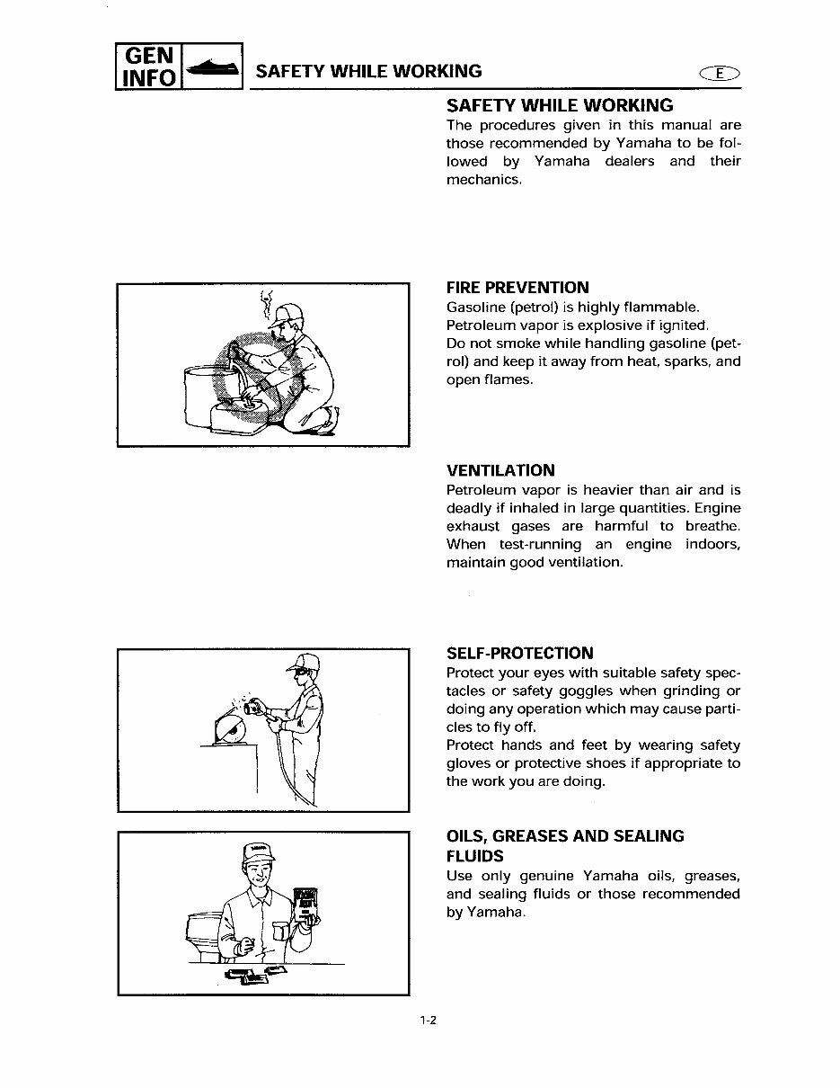
I GEN I • a I SAFETY WHILE WORKING INFO . CD 1-2 SAFETY WHILE WORKING The procedures given in this manual are those recommended by Yamaha to be fol- lowed by Yamaha dealers and their mechanics. FIRE PREVENTION Gasoline (petrol) is highly flammable. Petroleum vapor is explosive if ignited. Do not smoke while handling gasoline (pet- rol) and keep it away from heat, sparks, and open flames. VENTILATION Petroleum vapor is heavier than air and is deadly if inhaled in large quantities. Engine exhaust gases are harmful to breathe. When test-running an engine indoors, maintain good ventilation. SELF-PROTECTION Protect your eyes with suitable safety spec- tacles or safety goggles when grinding or doing any operation which may cause parti- cles to fly off. Protect hands and feet by wearing safety gloves or protective shoes if appropriate to the work you are doing. OILS, GREASES AND SEALING FLUIDS Use only genuine Yamaha oils, greases, and sealing fluids or those recommended by Yamaha. http://ReadManuals.com
This manual covers all versions of the following machines:
1998 YAMAHA WAVERUNNER GP800 PERSONAL WATERCRAFTS
1999 YAMAHA WAVERUNNER GP800 PERSONAL WATERCRAFTS
2000 YAMAHA WAVERUNNER GP800 PERSONAL WATERCRAFTS
After payment, our informative repair manual, owners manuals, and parts catalogs contain all the information you'll need to perform repairs, look up parts, or do routine maintenance on your machine. You will have access to information regarding the following topics:
General Information
Routine Maintenance
Engine Removal and Installation
Fuel System
Lubrication and Cooling System
Engine Specifications
Transmission, Drive Chain & Sprockets
Steering System
Shocks
Body Work
Intake & Exhaust
Electrical System
Advanced Troubleshooting
And much more! With our repair manuals, find the page pertaining to your job, print it off, and get working on your machine. No more ruining your expensive paper shop manual with grease and dirt.
Broke down on the trail or site and have a smartphone? What a cool way to find your problem and repair it on the trail, no downtime on the job site. With our repair manuals, you instantly have access to the material needed to get you running again. Kind of tough to do that with a paper manual.
And did we mention the fact that you're saving the trees... All our repair manuals come with a lifetime protection policy. If lost or damaged, simply contact us and we'll replace it free of charge for life.
We provide various repair service manuals, workshop manuals, repair manuals, owners manuals, parts catalogs, and other various manuals, all in an electronic format.
UTVs, motorcycles, ATVs, quads, snowmobiles, Seadoo, equipment, small engines, inboards, outboards, and more.
Instant Access after Payment
No Shipping Cost with Download
Get a Download so no waiting, repair it now...
Instant Access after Payment. Thank you.
Recently Viewed
5,521,897Happy Clients
2,594,462eManuals
1,120,453Trusted Sellers
15Years in Business
Price:
Actual Price:
1998-2000 Yamaha WaveRunner GP800 Personal Watercraft Repair Manual