

2004-2007 Yamaha WaveRunner FX1100 Service & Repair Manual
What's Included?
Fast Download Speeds
Online & Offline Access
Access PDF Contents & Bookmarks
Full Search Facility
Print one or all pages of your manual

E
HOW TO USE THIS MANUAL
MANUAL FORMAT
All of the procedures in this manual are organized in a sequential, step-by-step format. The informa-
tion has been compiled to provide the mechanic with an easy to read, handy reference that contains
comprehensive explanations of all disassembly, repair, assembly, and inspection operations.
In this revised format, the condition of a faulty component will precede an arrow symbol and the
course of action required will follow the symbol, e.g.,
• Bearings
Pitting/scratches → Replace.
To assist you in finding your way through this manual, the section title and major heading is given at
the top of every page.
ILLUSTRATIONS
The illustrations within this service manual represent all of the designated models.
CROSS REFERENCES
The cross references have been kept to a minimum. Cross references will direct you to the appropri-
ate section or chapter.
E
IMPORTANT INFORMATION
In this Service Manual particularly important information is distinguished in the following ways.
The Safety Alert Symbol means ATTENTION! BECOME ALERT! YOUR SAFETY IS
INVOLVED!
WARNING
Failure to follow WARNING instructions could result in severe injury or death to the machine
operator, passenger(s), a bystander, or a person inspecting or repairing the watercraft.
CAUTION:
A CAUTION indicates special precautions that must be taken to avoid damage to the water-
craft.
NOTE:
A NOTE provides key information to make procedures easier or clearer.
IMPORTANT:
This part has been subjected to change of specification during production.
E
HOW TO USE THIS MANUAL
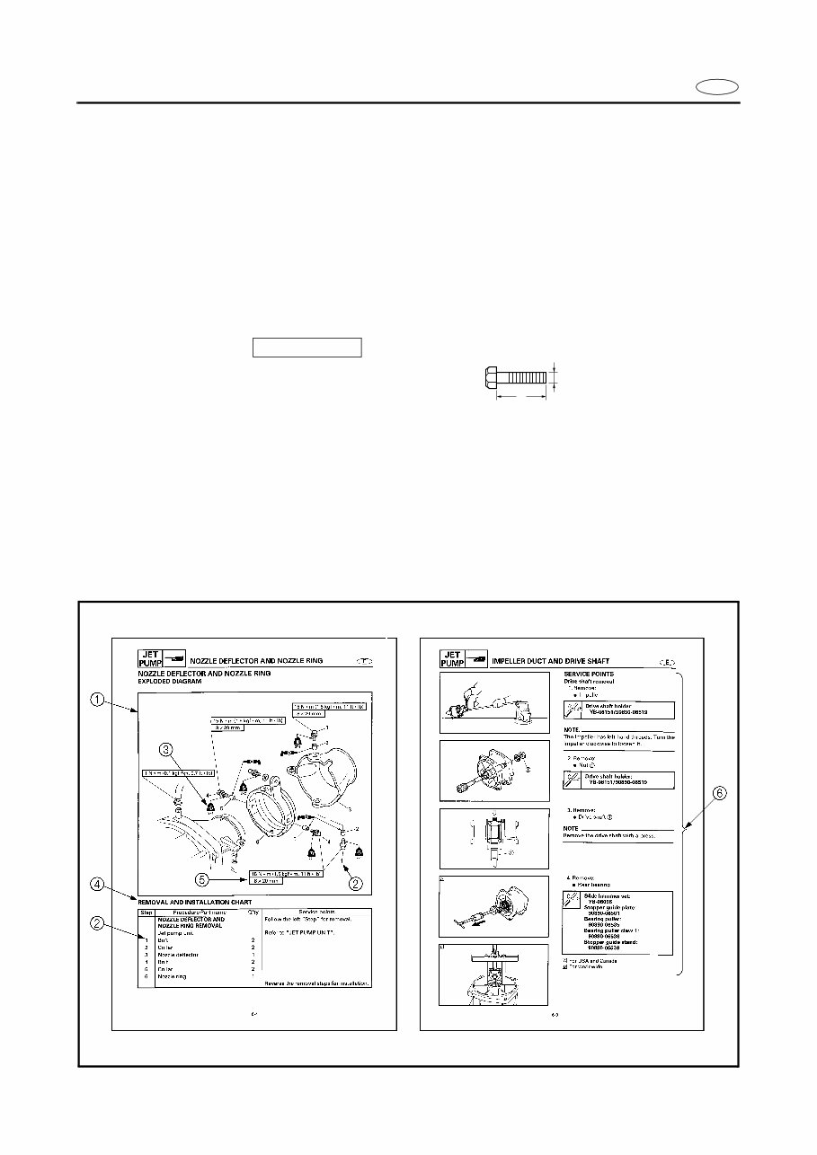
1 To help identify parts and clarify procedure steps, there are exploded diagrams at the start of
each removal and disassembly section.
2 Numbers are given in the order of the jobs in the exploded diagram.
3 Symbols indicate parts to be lubricated or replaced (see “SYMBOLS”).
4 A job instruction chart accompanies the exploded diagram, providing the order of jobs, names of
parts, notes in jobs, etc.
5 Dimension figures and the number of parts, are provided for fasteners that require a tightening
torque.
Example:
Bolt or screw size : M10 (D) × 25 mm (L)
6 Jobs requiring more information (such as special tools and technical data) are described
sequentially.
10 × 25 mm
D
L
E
A50001-1-4
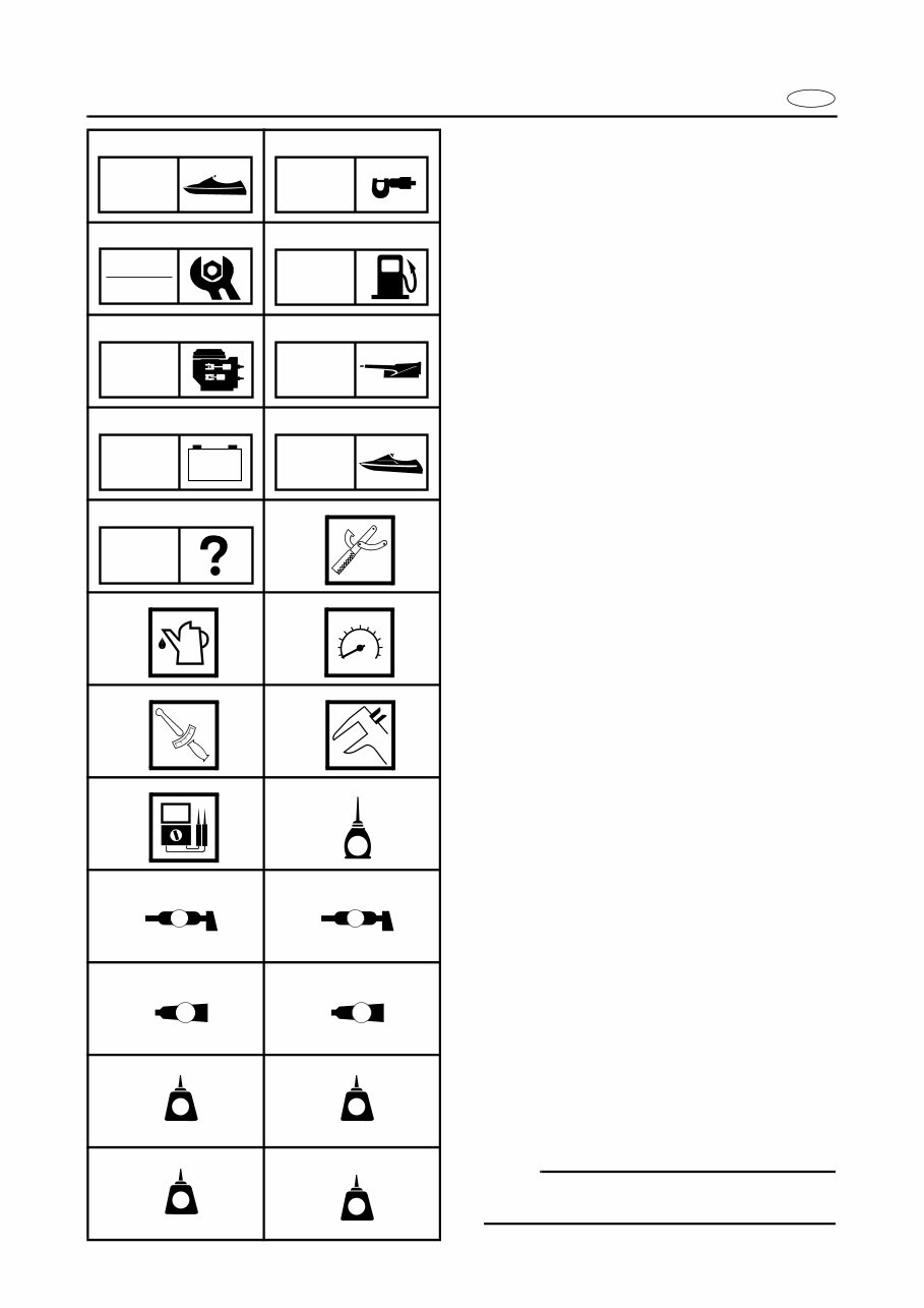
SYMBOLS
Symbols 1 to 9 are designed to indicate the
content of a chapter.
1 General Information
2 Specifications
3 Periodic Inspection and Adjustment
4 Fuel System
5 Power Unit
6 Jet Pump Unit
7 Electrical System
8 Hull and Hood
9 Trouble Analysis
Symbols 0 to E indicate specific data.
0 Special tool
A Specified oil or fluid
B Specified engine speed
C Specified tightening torque
D Specified measurement
E Specified electrical value
(resistance, voltage, electric current)
Symbols F to H in an exploded diagram indi-
cate the grade of lubricant and the lubrication
point.
F Apply Yamaha 4-stroke motor oil
G Apply water resistant grease
(Yamaha grease A, Yamaha marine grease)
H Apply molybdenum disulfide grease
Symbols I to N in an exploded diagram indi-
cate the type of sealant or locking agent and
the application point.
I Apply Gasket Maker
J Apply Yamabond No. 4
K Apply LOCTITE 271 (red)
L Apply LOCTITE 242 (blue)
M Apply LOCTITE 572
N Apply silicone sealant
NOTE:
Additional symbols may be used in this man-
ual.
1 2
3 4
5 6
7 8
9 0
A B
C D
E F
G H
I J
K L
M N
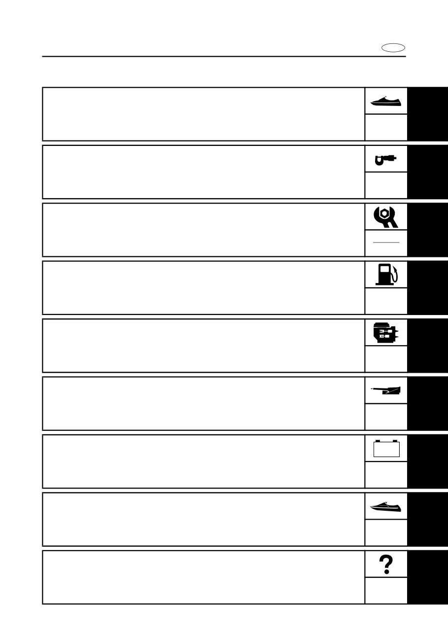
GEN
INFO
SPEC
INSP
ADJ
FUEL
POWR
JET
PUMP
– +
ELEC
HULL
HOOD
TRBL
ANLS
T
R
.
.
E
A M
GM
4
271
LT
242
LT
572
LT
SS
E
INDEX
GENERAL INFORMATION
1
GEN
INFO
SPECIFICATIONS
2
SPEC
PERIODIC INSPECTION AND
ADJUSTMENT
3
INSP
ADJ
FUEL SYSTEM
4
FUEL
POWER UNIT
5
POWR
JET PUMP UNIT
6
JET
PUMP
ELECTRICAL SYSTEM
7
ELEC
HULL AND HOOD
8
HULL
HOOD
TROUBLE ANALYSIS
9
TRBL
ANLS
– +
A30000-0
E
GEN
INFO
1
2
3
4
5
6
7
8
9
CHAPTER 1
GENERAL INFORMATION
IDENTIFICATION NUMBERS ......................................................................... 1-1
PRIMARY l.D. NUMBER ........................................................................... 1-1
ENGINE SERIAL NUMBER ...................................................................... 1-1
JET PUMP UNIT SERIAL NUMBER ......................................................... 1-1
HULL IDENTIFICATION NUMBER (H.l.N.) ............................................... 1-1
SAFETY WHILE WORKING...................................................................... 1-2
FIRE PREVENTION .................................................................................. 1-2
VENTILATION ........................................................................................... 1-2
SELF-PROTECTION ................................................................................. 1-2
PARTS, LUBRICANTS, AND SEALANTS ................................................ 1-2
GOOD WORKING PRACTICES ............................................................... 1-3
DISASSEMBLY AND ASSEMBLY ............................................................ 1-4
SPECIAL TOOLS ............................................................................................ 1-5
MEASURING ............................................................................................. 1-5
REMOVAL AND INSTALLATION .............................................................. 1-7
1-1
E
GEN
INFO
IDENTIFICATION NUMBERS
A60700-0*
IDENTIFICATION NUMBERS
PRIMARY l.D. NUMBER
The primary l.D. number is stamped on a label
attached to the inside of the engine compart-
ment.
Starting primary l.D. number:
F1S: 800101
ENGINE SERIAL NUMBER
The engine serial number is stamped on a
label attached to the engine unit.
Starting serial number:
6B6: 1000001
JET PUMP UNIT SERIAL NUMBER
The jet pump unit serial number is stamped on
a label attached to the intermediate housing.
HULL IDENTIFICATION NUMBER
(H.l.N.)
The H.l.N. is stamped on a plate attached to
the aft deck.
1-2
E
GEN
INFO
SAFETY WHILE WORKING
SAFETY WHILE WORKING
To prevent and accident or injury and to
ensure quality service, follow the safety proce-
dures provided below.
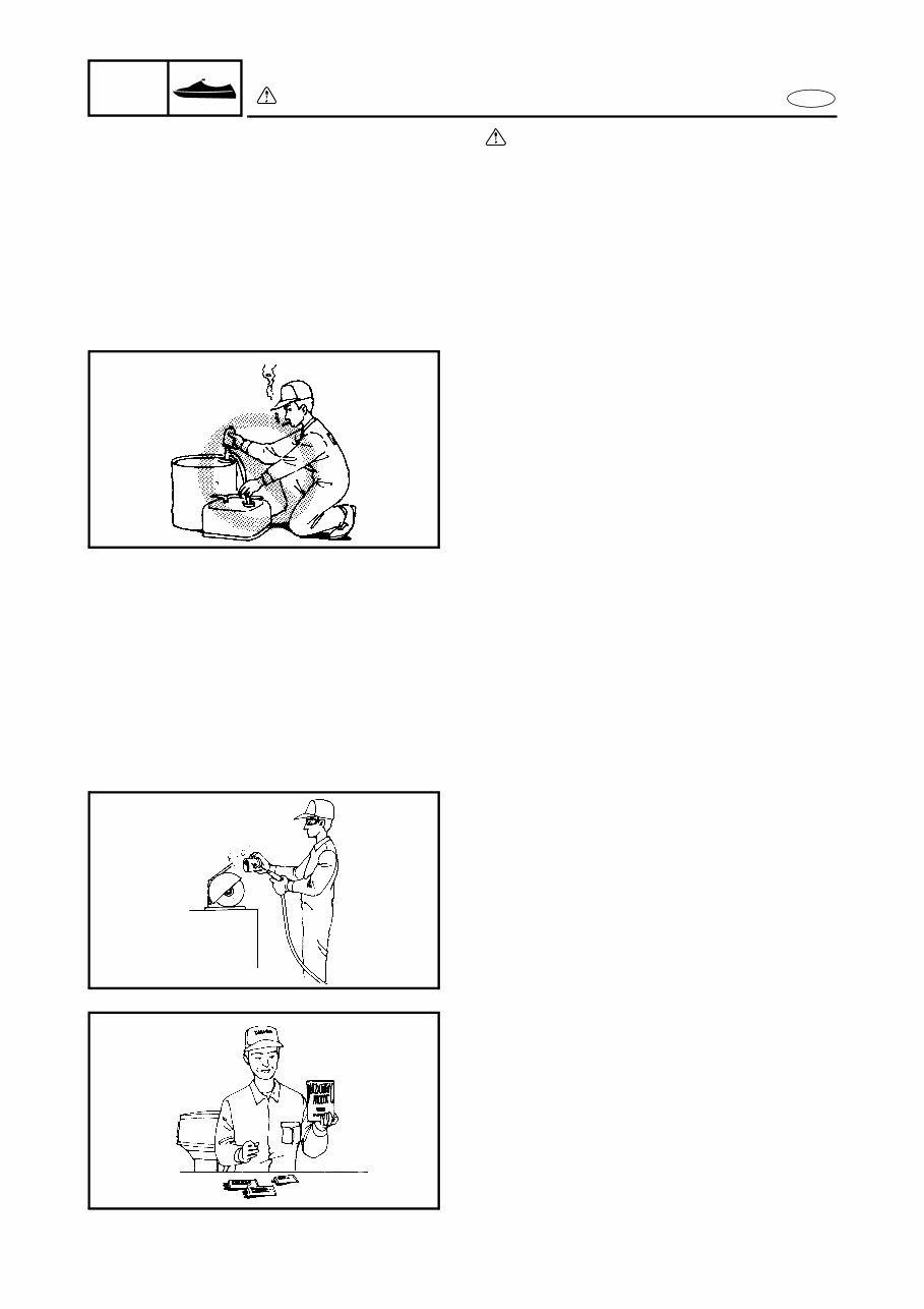
FIRE PREVENTION
Gasoline is highly flammable.
Keep gasoline and all flammable products
away from heat, sparks, and open flames.
VENTILATION
Gasoline vapor and exhaust gas are heavier
than air and extremely poisonous. If inhaled in
large quantities they may cause loss of con-
sciousness and death within a short time.
When test running an engine indoors (e.g., in a
water tank), be sure to do so where adequate
ventilation can be maintained.
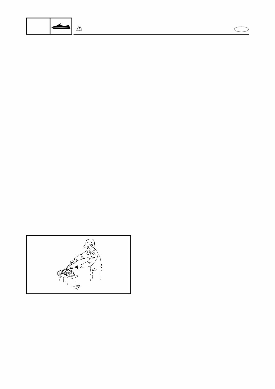
SELF-PROTECTION
Protect your eyes by wearing safety glasses or
safety goggles during all operation involving
drilling and grinding, or when using an air com-
pressor.
Protect your hands and feet by wearing protec-
tive gloves or safety shoes when necessary.
PARTS, LUBRICANTS, AND
SEALANTS
Use only genuine Yamaha parts, lubricants,
and sealants or those recommended by
Yamaha, when servicing or repairing the
watercraft.
1-3
E
GEN
INFO
SAFETY WHILE WORKING
Under normal conditions, the lubricants men-
tioned in this manual should not harm or be
hazardous to your skin. However, you should
follow these precautions to minimize any risk
when working with lubricants.
1. Maintain good standards of personal and
industrial hygiene.
2. Change and wash clothing as soon as
possible if soiled with lubricants.
3. Avoid contact with skin. Do not, for exam-
ple, place a soiled rag in your pocket.
4. Wash hands and any other part of the
body thoroughly with soap and hot water
after contact with a lubricant or lubricant
soiled clothing has been made.
5. To protect your skin, apply a protective
cream to your hands before working on the
watercraft.
6. Keep a supply of clean, lint-free cloths for
wiping up spills, etc.
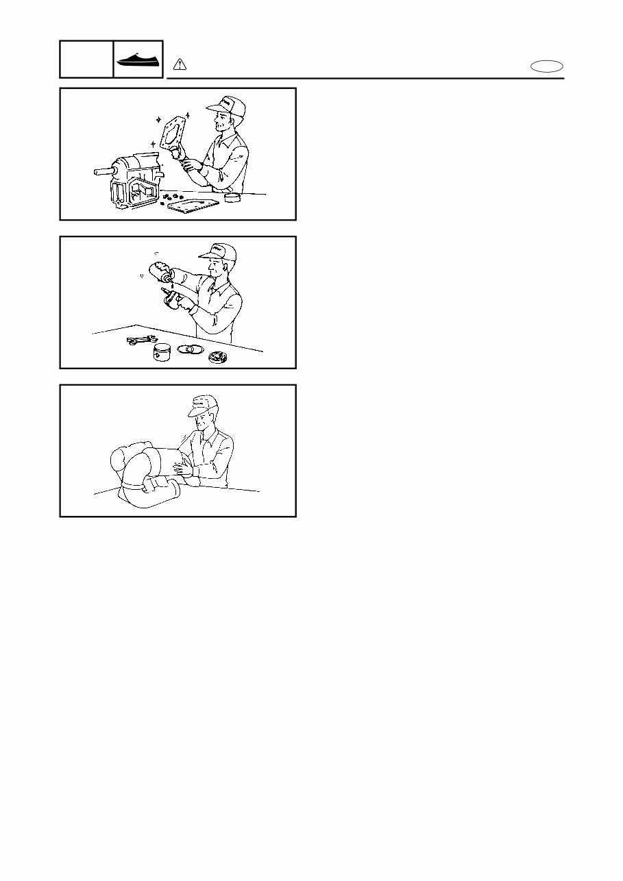
GOOD WORKING PRACTICES
1. The right tools
Use the recommended special service
tools to protect parts from damage. Use
the right tool in the right manner—do not
improvise.
2. Tightening torques
Follow the tightening torque specifications
provided throughout the manual. When
tightening nuts, bolts, and screws, tighten
the large sizes first, and tighten fasteners
starting in the center and moving outward.
1-4
E
GEN
INFO
SAFETY WHILE WORKING
3. Non-reusable parts
Always use new gaskets, seals, O-rings,
oil seals, cotter pins, circlips, etc., when
installing or assembling parts.
DISASSEMBLY AND ASSEMBLY
1. Use compressed air to remove dust and
dirt during disassembly.
2. Apply engine oil to the contact surfaces of
moving parts during assembly.
3. Install bearings with the manufacture iden-
tification mark in the direction indication in
the installation procedure. In addition, be
sure to lubricate the bearings liberally.
4. Apply a thin coat of water-resistant grease
to the lip and periphery of an oil seal
before installation.
5. Check that moving parts operate normally
after assembly.
You're Reading a Preview
What's Included?
Fast Download Speeds
Online & Offline Access
Access PDF Contents & Bookmarks
Full Search Facility
Print one or all pages of your manual
$31.99
Viewed 31 Times Today


Secure transaction
What's Included?
Fast Download Speeds
Online & Offline Access
Access PDF Contents & Bookmarks
Full Search Facility
Print one or all pages of your manual
$31.99
Get your hands on the comprehensive factory repair manual for the 2004-2007 Yamaha WaveRunner FX1100 4-stroke personal watercraft. This manual covers the following models:
- 2004-2007 Yamaha WaveRunner FX
- 2004-2007 Yamaha WaveRunner FX High Output
- 2004-2007 Yamaha WaveRunner FX Cruiser High Output
With 794 pages of detailed instructions, this manual includes complete tear down and rebuild procedures, along with pictures and part diagrams, torque specifications, maintenance guidelines, and troubleshooting techniques. It is designed to cater to the needs of both professional mechanics and DIY enthusiasts. The manual features clickable chapters and is searchable, allowing for easy navigation to find the information you need. Additionally, there are no restrictions on printing or saving/burning to disc.


