SMR2001_001_00A2.FM I SECTION SUBSECTION PAGE SAFETY NOTICE .................................................................................................................................. III WHAT’S NEW ....................................................................................................................................... IV INTRODUCTION ................................................................................................................................... VI 01 SERVICE TOOLS AND PRODUCTS 01 - Table of contents ...................................................................... 01-01-1 02 - Mandatory service tools ............................................................ 01-02-1 03 - Optional service tools................................................................ 01-03-1 04 - Service products ....................................................................... 01-04-1 02 MAINTENANCE 01 - Table of contents ...................................................................... 02-01-1 02 - Periodic inspection chart ........................................................... 02-02-1 03 - Flushing and lubrication............................................................. 02-03-1 04 - Water-flooded engine................................................................ 02-04-1 05 - Storage ...................................................................................... 02-05-1 03 TROUBLESHOOTING 01 - Troubleshooting chart ............................................................... 03-01-1 04 ENGINE 01 - Table of contents ...................................................................... 04-01-1 02 - Leak test ................................................................................... 04-02-1 03 - Removal and installation ........................................................... 04-03-1 04 - Magneto system ....................................................................... 04-04-1 05 - Top end ..................................................................................... 04-05-1 06 - Bottom end ............................................................................... 04-06-1 07 - Rotary valve............................................................................... 04-07-1 08 - Exhaust system......................................................................... 04-08-1 05 ENGINE MANAGEMENT (RFI) 01 - Table of contents ...................................................................... 05-01-1 02 - Overview ................................................................................... 05-02-1 03 - Diagnostic procedures .............................................................. 05-03-1 04 - Component inspection .............................................................. 05-04-1 05 - Troubleshooting summary ........................................................ 05-05-1 06 - Adjustment................................................................................ 05-06-1 07 - Removal and installation ........................................................... 05-07-1 06 ENGINE MANAGEMENT (DI) 01 - Table of contents ...................................................................... 06-01-1 02 - Overview ................................................................................... 06-02-1 03 - Component inspection and adjustment .................................... 06-03-1 04 - Diagnostic procedures .............................................................. 06-04-1 07 COOLING SYSTEM 01 - Table of contents ...................................................................... 07-01-1 02 - Circuit, components and care ................................................... 07-02-1 08 FUEL SYSTEM 01 - Table of contents ...................................................................... 08-01-1 02 - Fuel circuit ................................................................................. 08-02-1 03 - Air intake ................................................................................... 08-03-1 04 - Carburetor ................................................................................. 08-04-1 09 LUBRICATION SYSTEM 01 - Table of contents ...................................................................... 09-01-1 02 - Oil injection system................................................................... 09-02-1 03 - Oil injection pump ..................................................................... 09-03-1 TABLE OF CONTENTS
II SMR2001_001_00A2.FM 10 ELECTRICAL SYSTEM 01 - Table of contents ...................................................................... 10-01-1 02 - Ignition system ......................................................................... 10-02-1 03 - Charging system....................................................................... 10-03-1 04 - Starting system......................................................................... 10-04-1 05 - Instruments and accessories .................................................... 10-05-1 06 - Digitally encoded security system (DESS) ................................ 10-06-1 11 PROPULSION SYSTEM 01 - Table of contents ...................................................................... 11-01-1 02 - Jet pump................................................................................... 11-02-1 03 - Drive system............................................................................. 11-03-1 04 - Reverse system........................................................................ 11-04-1 05 - Variable trim system ................................................................. 11-05-1 12 STEERING SYSTEM 01 - Table of contents ...................................................................... 12-01-1 02 - Steering system........................................................................ 12-02-1 03 - Alignment ................................................................................. 12-03-1 13 SUSPENSION 01 - Table of contents ...................................................................... 13-01-1 02 - Direct action suspension .......................................................... 13-02-1 14 HULL/BODY 01 - Table of contents ...................................................................... 14-01-1 02 - Adjustment and repair .............................................................. 14-02-1 15 TECHNICAL DATA 01 - GS model .................................................................................. 15-01-1 02 - GTI and GTS models ................................................................. 15-02-1 03 - GTX RFI model.......................................................................... 15-03-1 04 - XP model .................................................................................. 15-04-1 05 - GTX and RX models .................................................................. 15-05-1 06 - GTX DI and RX DI models......................................................... 15-06-1 16 WIRING DIAGRAMS 01 - Wiring diagrams ........................................................................ 16-01-1 TABLE OF CONTENTS
SMR2001_001_00A2.FM III SAFETY NOTICE 0 This manual has been prepared as a guide to correctly service and repair all 2001 SEA-DOO watercraft. See model list below. This edition was primarily published to be used by watercraft mechanical technicians who are already familiar with all service procedures relating to Bombardier made watercraft. Mechanical technicians should attend training courses given by Bombardier Training Dept. Please note that the instructions will apply only if proper hand tools and special service tools are used. This Shop Manual uses technical terms which may be slightly different from the ones used in the Parts Catalog. It is understood that this manual may be translated into another language. In the event of any discrepancy, the English version shall prevail. The content depicts parts and/or procedures applicable to the particular product at time of writing. Service and Warranty Bulletins may be published to update the content of this manual. Make sure to read and understand these. In addition, the sole purpose of the illustrations throughout the manual, is to assist identification of the general configuration of the parts. They are not to be interpreted as technical drawings or exact replicas of the parts. The use of Bombardier parts is most strongly recommended when considering replacement of any com- ponent. Dealer and/or distributor assistance should be sought in case of doubt. The engines and the corresponding components identified in this document should not be utilized on product(s) other than those mentioned in this document. Torque wrench tightening specifications must be strictly adhered to. Locking devices (ex.: locking tab, self-locking fasteners, etc.) must be installed or replaced with new ones. If the efficiency of a locking device is impaired, it must be renewed. This manual emphasizes particular information denoted by the wording and symbols: CAUTION: Denotes an instruction which, if not followed, could severely damage vehicle components. NOTE: Indicates supplementary information needed to fully complete an instruction. Although the mere reading of such information does not eliminate the hazard, your understanding of the information will promote its correct use. Always use common shop safety practice. Bombardier Inc. disclaims liability for all damages and/or injuries resulting from the improper use of the contents. We strongly recommend that any services be carried out and/or verified by a highly skilled professional mechanic. It is understood that certain modifications may render use of the vehicle illegal under existing federal, provincial and state regulations. WARNING Identifies an instruction which, if not followed, could cause serious personal injury including possibility of death. SAFETY NOTICE
IV SMR2001_001_00A2.FM WHAT’S NEW 0 THIS SECTION INDICATES PROCEDURES THAT WERE MODIFIED OR NEWLY ADDED IN THIS MANUAL. RX, RX DI and GTX DI models have been merged with this manual. RFI fuel injection section has been relocated in its own Engine Management section. SERVICE TOOLS AND PRODUCTS The following new tools have been added: • Oil seal pusher for 787 RFI engines. • Crankshaft protective cap for all models. • Deutsch tool for joint connector on DI models. • New Loctite safety solvant number. • New Anti-seize lubricant number. MAINTENANCE • Updated storage procedure. TROUBLESHOOTING • Updated ENGINE • New sequence to torque tuned pipe (all models). ENGINE MANAGEMENT (RFI) • Added conversion chart for temperature sensors. • Added the general part. • Updated fault code table. • Updated the water temperature sensor tests. ENGINE MANAGEMENT (DI) • Updated the conversion chart for temperature sensors. • Added a quick air/fuel pressure test. • Updated throttle body synchronization. • Updated procedures for fuel injector, fuel pessure regulator and air pessure regulator available as single spare parts. • Updated MPEM replacement procedure. • Updated the fuel delivery system diagnostic flow chart. COOLING SYSTEM • New diagram for the cooling system (all engines). WHAT’S NEW
SMR2001_001_00A2.FM V FUEL SYSTEM • Updated procedure for air intake silencer removal/installation. • Revised injector check valve pressure test on accelerator pump. LUBRICATION SYSTEM • Revised illustrations for oil injection pump adjustment. ELECTRICAL SYSTEM • Updated charging system procedure for RFI model. PROPULSION SYSTEM • Updated impeller chart. • New procedure for oil inspection in jet pump. • New procedure to remove venturi. • New procedure to install bearings and seals in the housing. • New tightening sequence for seal carrier of the mid bearing on the XP. • New procedure to remove variable trim system on RX series. HULL/BODY • Seat adjustment for GTS/GTI/RX and RX DI. • New drain plug. • Tightening sequence for ride shoe. TECHNICAL DATA • Updated specifications for each model. WIRING DIAGRAMS • Added procedure to service the 30 A fuse on DI models. • Updated wiring diagrams for each model. WHAT’S NEW
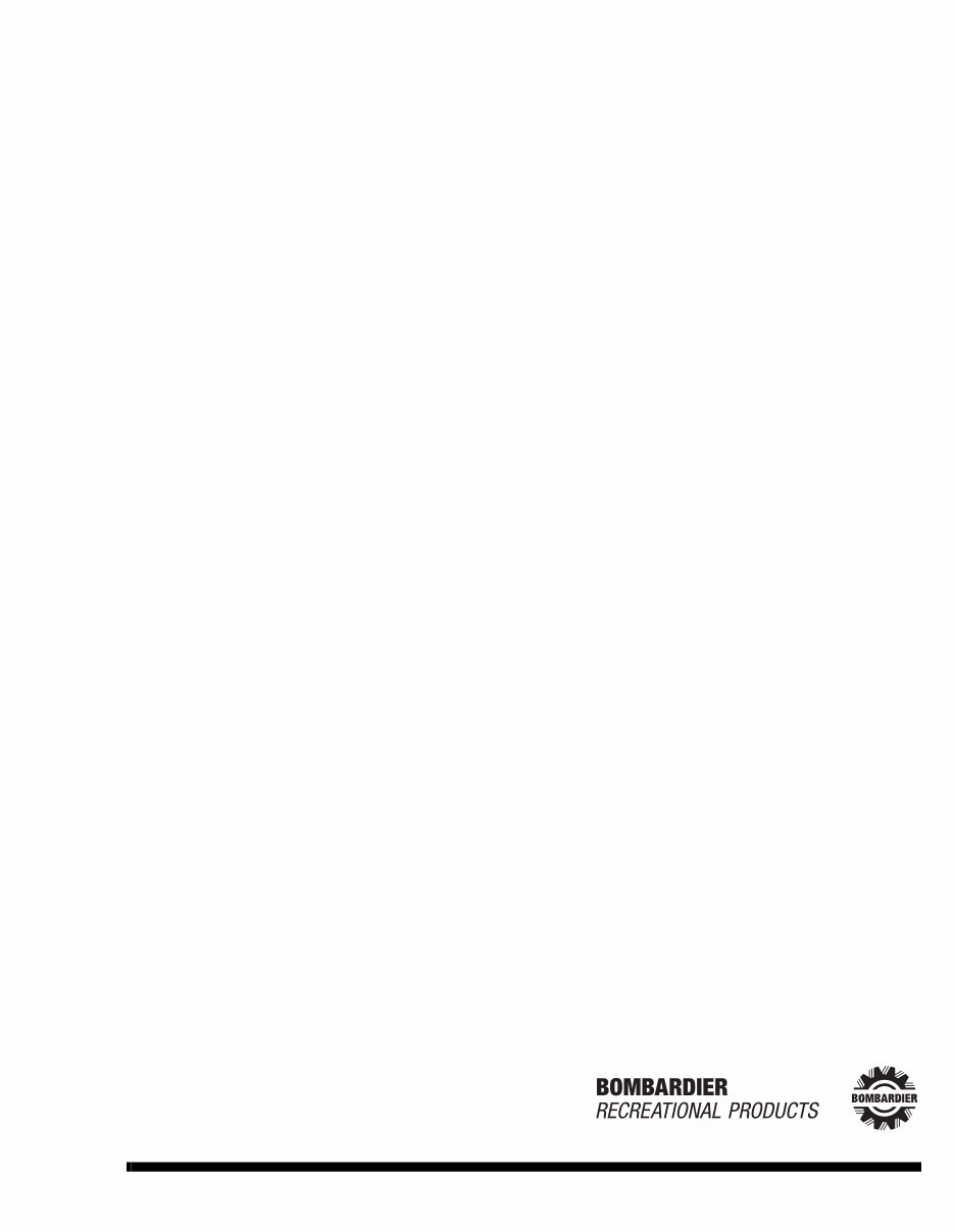
INTRODUCTION VI SMR2001_001_00A2.FM INTRODUCTION 0 This Shop Manual covers the following BOMBAR- DIER made SEA-DOO ® 2001 watercraft models. HULL IDENTIFICATION NUMBER (H.I.N.) It is located on footboard at the rear of watercraft. GTS, GTI and RX Series 1. Hull Identification Number (H.I.N.) All Other Models TYPICAL 1. Hull Identification Number (H.I.N.) MODELS ENGINE TYPE MODEL NUMBER GS 717 5519 GS International 717 5518 XP 947 5531 XP International 947 5530 GTS 717 5521 GTS International 717 5520 GTI 717 5523 GTI International 717 5522 GTX (red) 947 5527 GTX International (red) 947 5526 GTX (blue) 947 5538 GTX International (blue) 947 5539 GTX RFI 787 5525 GTX RFI International 787 5524 GTX RFI (green) 787 5555 GTX RFI International (green) 787 5553 GTX DI (blue) 947 DI 5529 GTX DI International (blue) 947 DI 5528 GTX DI (red) 947 DI 5541 GTX DI International (red) 947 DI 5540 RX (blue) 947 5533 RX International (blue) 947 5532 RX (yellow) 947 5543 RX International (yellow) 947 5542 RX DI (blue) 947 5535 RX DI International (blue) 947 DI 5534 RX DI (yellow) 947 DI 5537 RX DI International (yellow) 947 DI 5536 F08L0QA 1 INTRODUCTION
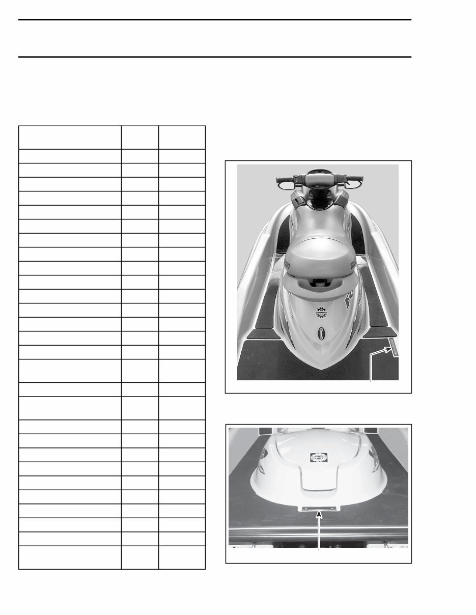
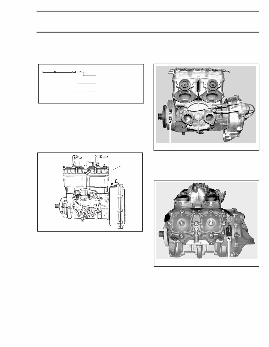
INTRODUCTION SMR2001_001_00A2.FM VII All Models The Hull Identification Number is composed of 12 digits: ENGINE IDENTIFICATION NUMBER (E.I.N.) 717 Engine The Engine Identification Number is located on the upper side of the magneto housing. TYPICAL 1. Engine Identification Number (E.I.N.) 787 RFI Engine The Engine Identification Number is located on the upper crankcase on PTO side. 1. Engine Identification Number (E.I.N.) 947 Engine The Engine Identification Number is located on the upper crankcase on MAGNETO side. 1. Engine Identification Number (E.I.N.) 1 F01D01A INTRODUCTION
INTRODUCTION VIII SMR2001_001_00A2.FM ARRANGEMENT OF THIS MANUAL The manual is divided into 16 major sections: 01 SERVICE TOOLS AND PRODUCTS 02 MAINTENANCE 03 TROUBLESHOOTING 04 ENGINE 05 ENGINE MANAGEMENT (RFI) 06 ENGINE MANAGEMENT (DI) 07 COOLING SYSTEM 08 FUEL SYSTEM 09 LUBRICATION SYSTEM 10 ELECTRICAL SYSTEM 11 PROPULSION SYSTEM 12 STEERING SYSTEM 13 SUSPENSION 14 HULL/BODY 15 TECHNICAL DATA 16 WIRING DIAGRAM Several sections are divided in various subsections. There is a table of contents at the beginning of many sections. INTRODUCTION
This workshop repair service manual is designed to cover the repair and overhaul of Sea-Doo GTX DI 2001 cars. It assumes that the technician is fully conversant with general automobile practices and emphasizes the special aspects of the product. The manual includes instructions on components manufactured for Sea-Doo GTX DI 2001, as well as repairs of proprietary components. It provides information such as tune-ups, maintenance, removal & install procedures, assemblies & disassemblies, fuel system, ignition, lubrication system, exhaust, electrical system, body, and more extensive repair involving engine and transmission disassembly for Sea-Doo GTX DI 2001.
The manual aims to provide the most reliable information to help you get the best value from your Sea-Doo GTX DI 2001. It includes many of the specifications and procedures available in an authorized Sea-Doo GTX DI 2001 dealer service department, offering diagnostic and repair procedures to follow when trouble occurs.
For those intending to do maintenance and repair on their Sea-Doo GTX DI 2001, it is essential that safety equipment be used and safety precautions observed when working on the vehicle. The manual also refers to special tools that are recommended or required to accomplish adjustments or repairs, often identified by their Sea-Doo GTX DI 2001 special tool number and illustrated.
Owning and referring to this manual will make it possible to be better informed and to more knowledgeably repair the Sea-Doo GTX DI 2001 like a professional automotive technician.
Specification:
This is a FORM NOT A HARD COPY!!!
FAST and FREE ELECTRONIC DELIVERY via Email!!!
Language: English
Printable: Yes
File Format: .PDF
General Maintenance Tags for WSMBEST Workshop Service Manuals:
Air cleaner element renewal
Air cleaner temperature control check
Auxiliary drive belt check
Battery electrolyte level check
Battery terminal check
Brake hydraulic fluid renewal
Brake hydraulic system seal and hose renewal
Brake pipe and hose check
Choke adjustment check
Contact breaker point renewal and distributor lubrication
Crankcase ventilation system check
Emission control filter element renewal
Engine coolant renewal
Engine idle speed check
Engine oil and filter renewal
Engine valve clearance check - OHV engines
Exhaust system check
Fluid leak check
Fluid level checks
Front and rear brake pad/shoe check
Front wheel alignment check
Gearbox oil level check
Handbrake check
Hinge and lock check and lubrication
HT lead, distributor cap
Ignition circuit check
Ignition timing
Contact breaker gap (dwell angle) check
Intensive maintenance
Mixture adjustment check
Road test
Roadwheel security check
Seat belt check
Spark plug check
Spark plug renewal
Steering and suspension security check
Throttle damper operation check
Timing belt renewal
Tyre checks
Underbody inspection
Wiper blade check
Sea-Doo GTX DI 2001 Workshop Repair Service Manual.