General Information 2 VPA 7743614 English 07-2005 Good Service Practice Service required for the engine and sterndrive is generally one of three kinds: • Normal care and maintenance - which includes putting a new engine and stern drive into operation, storing, lubrication, and care under special operating conditions such as salt water and cold weather. • Operating malfunctions - due to improper engine or drive mounting, propeller condition or size, boat condition, or the mal- function of some part of the engine. This includes engine ser- vicing procedures to keep the engine in prime operating condition. • Complete disassembly and overhaul - such as major service or rebuilding a unit. It is important to determine before disassembly just what the trouble is and how to correct it quickly, with minimum expense to the owner. When repairing an assembly, the most reliable way to ensure a good job is to do a complete overhaul on that assembly, rather than just to replace the bad part. Wear not readily apparent on other parts could cause malfunction soon after the repair job. Repair kits and seal kits contain all the parts needed to ensure a complete repair, to eliminate guesswork, and to save time. Repair time can also be minimized by the use of special tools. Volvo Penta special tools are designed to perform service procedures unique to the product that cannot be completed using tools from other sources. They also speed repair work to help achieve service flat rate times. In some cases, the use of substitute tools can damage the part. Preparation for Service Proper preparation is extremely helpful for efficient service work. A clean work area at the start of each job will minimize tools and parts becoming misplaced. Clean an engine that is excessively dirty before work starts. Cleaning will occasionally uncover trouble sources. Obtain tools, instruments and parts needed for the job before work is started. Interrupting a job to locate special tools or repair kits is a needless delay. Caution! Use proper lifting and handling equipment. Working on stern drives without proper equipment can cause damage and personal injury. Always use clean fresh fuel when testing engines. Troubles can often be traced to the use of old or dirty fuel. Service Policy It is a Volvo Penta policy to provide dealers with service knowledge so they can give professional service demanded by today’s consumer. The Volvo Penta Training Centers, frequent mailing of Service Bulle- tins, Letters and Promotions, Special Tools, Partner Network, and this Service Manual represent the latest effort to assist dealers in giving consumers the best and most prompt service possible. If a service question does not appear to be answered in this manual, you are invited to contact the Volvo Penta Service Department by calling or through Partner Network for additional help. Always be sure to give complete information, including engine model number and serial num- ber.
General Information VPA 7743614 English 07-2005 3 Replacement Parts Warning! When replacement parts are required, always use genuine Volvo Penta parts, or parts with equivalent characteristics, including type, strength, and material. Failure to do so may result in product malfunction and possible injury to the operator and/or passengers. Parts Catalogs Parts Catalogs and the electronic parts catalog (EPC) contain exploded views showing the correct assembly of all parts, as well as a complete listing of the parts for replacement. These catalogs are help- ful as a reference during disassembly and reassembly, and are avail- able from Partner Network and Volvo Penta Parts. Special Service Tools Volvo Penta has specially designed tools to simplify some of the disas- sembly and assembly operations. These tools are illustrated in this Service Manual, in many cases in actual use. All special tools can be ordered from Volvo Penta Parts. Individual purchasers of Service Man- uals must order Special Tools through an authorized dealer. Product References, Illustrations & Specifications Volvo Penta reserves the right to make changes at anytime, without notice, in specifications and models and also to discontinue models. The right is also reserved to change any specifications or parts at any time without incurring any obligation to equip same on models manu- factured prior to date of such change. All information, illustrations and specifications contained in this manual are based on the latest product information available at the time of printing. The right is reserved to make changes at anytime without notice. All photographs and illustrations used in this manual may not depict actual models or equipment, but are intended as representative views for reference only. The continuing accuracy of this manual cannot be guaranteed. The purpose of an engine tune-up is to restore power and perfor- mance that has been lost through wear, corrosion or deterioration of one or more parts or components. In the normal operation of an engine, these changes can take place gradually at a number of points, so that it is seldom advisable to attempt an improvement in perfor- mance by correction of one or two items only. Time will be saved and more lasting results will be obtained by following a definite and thor- ough procedure of analysis and correction of all items affecting power and performance. Economical, trouble-free operation can better be ensured if a complete tune-up is performed once every year, preferably in the spring. Com- ponents that affect power and performance can be divided into three groups: • Components affecting compression • Components affecting ignition • Components affecting fuel system Tuning the Engine Tune-up procedures should cover these groups in the order given. While the items affecting compression and ignition may be handled according to personal preference, correction of items in the fuel sys-
General Information 4 VPA 7743614 English 07-2005 tem group should not be attempted until all items affecting compres- sion and ignition have been satisfactorily corrected. Most of the procedures for performing a complete engine tune-up will be covered in greater detail in this manual. This section will deal mainly with the order of procedures involved in tuning the engine. Engine Compression Testing During all work done around the engine, while the engine is running or being cranked, use extreme care to avoid getting fingers or clothing caught in any belts, pulleys, or other moving parts. 2. Visually inspect stern drive unit for leaks, missing parts or other obvious defects. Replace deteriorated parts. 3. Compression check: Proper compression is essential for good engine performance. An engine with low or uneven compression cannot be properly tuned. • Operate engine to normal operating temperature. Caution! Engine must not be started and run without water for cool- ing. • Remove any foreign matter from around spark plugs by blowing out with compressed air. • Remove and inspect all spark plugs. Install thread-type com- pression gauge in spark plug hole. • Set the Volvo Penta Scan tool to “ECM TESTS” and select “COMPRESSION TEST” before cranking the engine. Caution! This test commands the ECM to disable all spark and fuel injector outputs. The test must be properly exited from the Scan Tool to re-enable normal spark and fuel operation. DO NOT perfrom this test in open water. Always perform this test dockside or on a trailer. The engine will be dis- abled until the test is properly exited. If the scan tool is disconnected during the COMPRES- SION TEST, the engine will remain disabled until the scan tool is reconnected and the COMPRESSION TEST mode is exited properly. Refer to the documentation that comes with the Scan tool for further information on Scan tool operation. Test Conclusion The indicated compression pressures are considered normal if the lowest reading cylinder is within 75% of the highest. Example: If the highest pressure reading was 140 PSI, 75% of 140 is 105. Therefore, any cylinder reading less than 105 PSI indicates an improp- erly seated valve, worn valve guides, piston, cylinder, or worn or bro- ken piston rings. Any cylinder reading 105 PSI or greater is within specifications, and compression is considered normal.
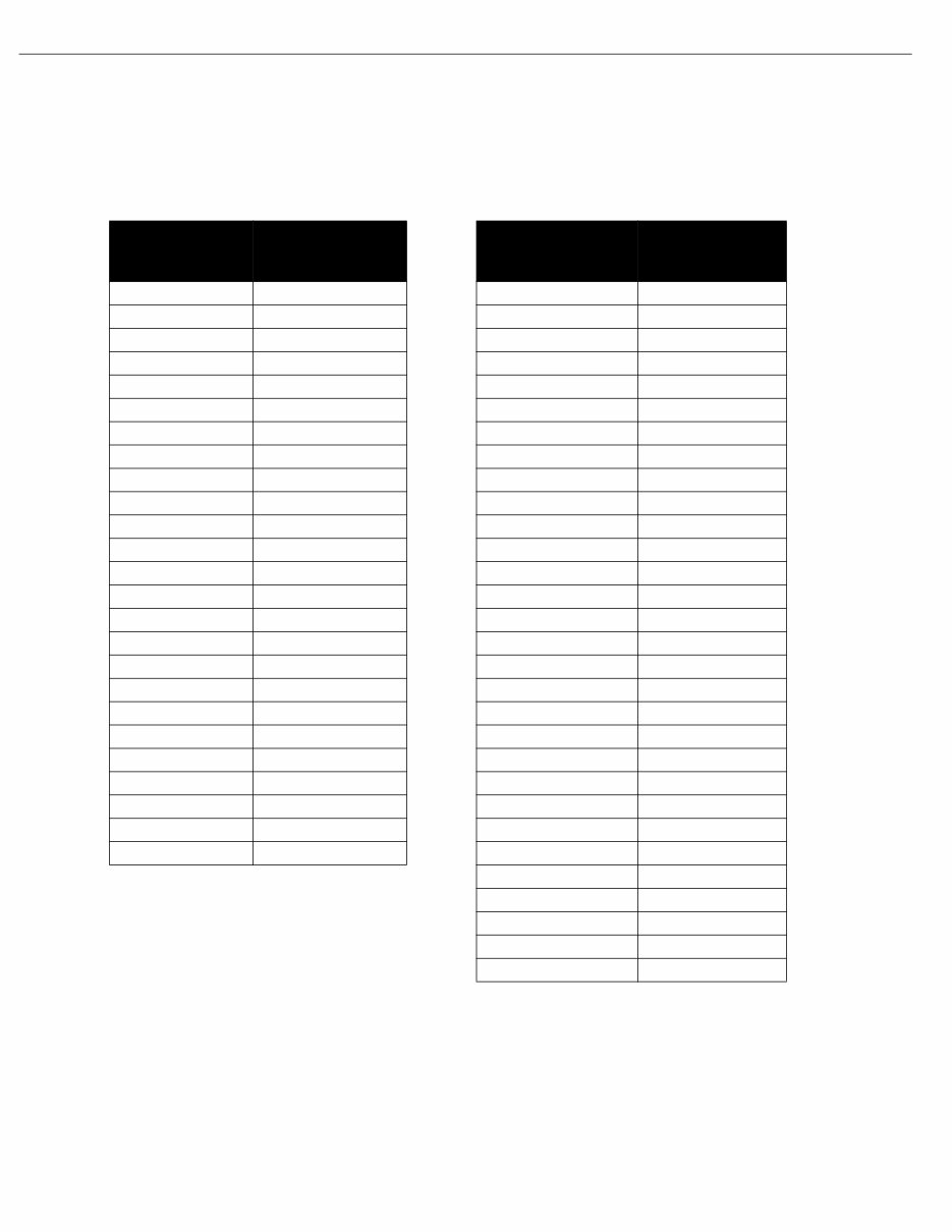
General Information VPA 7743614 English 07-2005 5 If one or more cylinders read low, squirt approximately one tablespoon of engine oil on top of the pistons in the low reading cylinders. Repeat compression pressure check on the cylinders. 1. If compression improves considerably, the piston rings are at fault. 2. If compression does not improve, valves are sticking or seating poorly, or valve guides are worn. 3. If two adjacent cylinders indicate low compression pressures and squirting oil on the pistons does not increase the compression, the cause may be a cylinder head gasket leak between the cylinders. This problem could allow engine oil and/or coolant to enter the cyl- inders. It is recommended the following quick reference chart be used when checking cylinder compression pressures. The chart has been calculated so that the lowest reading number is 75% of the highest reading. After checking cylinder compression, repairs should be made as nec- essary. Subsequent adjustments to an engine that does not have proper compression will not measurably improve performance or cor- rect operational problems. After verifying compression, check ignition and fuel system components. Ignition System Components • Spark Plugs • Spark Plug Leads • Distributor Cap • Rotor • Ignition Coil • High Tension Lead • Ignition Switch • Circuit Wiring and Connectors Fuel System Components • Fuel Tank Pickup and Screen Table 1: Compression Pressure Limit Max. PSI Min. PSI Max. PSI Min. PSI Max. PSI Min. PSI Max. PSI Min. PSI 134 101 154 115 174 131 194 145 136 102 156 117 176 132 196 147 138 104 158 118 178 133 196 148 140 105 160 120 180 135 200 150 142 107 162 121 182 136 202 151 144 108 164 123 184 138 204 153 146 110 166 124 186 140 206 154 148 111 168 126 188 141 208 156 150 113 170 127 190 142 210 157 152 114 172 129 192 144 212 158
General Information 6 VPA 7743614 English 07-2005 • Fuel Tank Vent • Anti-Siphon Valve (if equipped) • Fuel Octane and Quality • Boat Fuel Lines and Valves • External Engine Fuel Filter • Fuel Pump(s) and Line • Engine PCV Valve • Flame Arrestor All of the above listed components are not necessarily part of an engine tune-up, but must be considered when attempting to correct engine/boat performance problems. Repair or replace components only as required. Warning! Do not substitute automotive parts. Volvo Penta marine components meet U.S. Coast Guard regulations for exter- nal ignition proof operation and marine use. Volvo Penta marine components are specially designed not to cause ignition of fuel vapors in the bilge or engine compartment. The use of automotive parts can result in fire and explo- sion. Intake Manifold Vacuum Testing Test Procedures 1. Install a vacuum gauge to a good intake manifold source (usually at the PCV valve port), following the gauge manufacturer’s instruc- tions. Start and warm up the engine. 2. Observe the vacuum gauge while operating the engine over a range of engine speeds. Test Results 1. A steady vacuum reading between 14 and 19in. Hg. (47-64 kPa) at idle indicates an engine in good mechanical condition. 2. A vacuum reading below 14 in. Hg. (47 kPa) at idle, indicates an engine that is not developing enough vacuum. Further testing for base mechanical problems is needed. 3. Possible causes of low intake manifold vacuum are late ignition timing, low compression, poor engine sealing, leaks at vacuum lines and connections or bad MAP sensor. 4. If the gauge fluctuates at idle, possible causes are sticking or leak- ing valves, or an ignition miss. 5. If the gauge fluctuates at idle but smooths out as engine RPM increases, check for bad valves or camshaft. 6. If the gauge fluctuates more with increases engine RPM, check for weak or broken valve springs, bad valves, ignition miss, or a leak- ing head gasket. 7. If the vacuum gauge fluctuates regularly with each engine cycle, check for a bad valve.
Volvo Penta 4.3/5.0/5.7/8.1 EFI Marine Engine Service & Repair Manual
Models covered:
Volvo Penta 4.3GXi
Volvo Penta 4.3OSi
Volvo Penta 5.0GXi
Volvo Penta 5.0OSi
Volvo Penta 5.7Gi
Volvo Penta 5.7GiI
Volvo Penta 5.7GXi
Volvo Penta 5.7GXiI
Volvo Penta 5.7OSi
Volvo Penta 5.7OSXi
Volvo Penta 8.1Gi
Volvo Penta 8.1GiI
Volvo Penta 8.1GXi
Volvo Penta 8.1GXiI
This professional technical manual contains service, maintenance, troubleshooting, and replacement procedures for your engine, including step-by-step instructions, clear images, and exploded-view illustrations. It is useful for both professional mechanics and DIY enthusiasts.
The manufacturer-sourced and easy-to-understand procedures, once combined with illustrations, make it possible for anyone to safely and efficiently service and repair their engine.
This engine service & repair manual contains every troubleshooting and replacement procedure provided by the manufacturer, including step-by-step instructions, exploded-view illustrations, torque specs, and clear images — everything you need to diagnose, repair, or overhaul your engine in no time!
No need to flip through hundreds of pages to find specific information; no more greasy, torn, or lost pages anymore! Carry them around, search them, screenshot them, bookmark them — much better than a traditional bound manual if you ask me.
Of course, if you prefer to have a physical copy, nothing prevents you from printing it out too.
Printable: Yes Language: English Compatibility: Pretty much any electronic device, incl. PC & Mac computers, Android and Apple smartphones & tablet, etc. Requirements: Adobe Reader (free)
Recently Viewed
5,521,897Happy Clients
2,594,462eManuals
1,120,453Trusted Sellers
15Years in Business
Price:
Actual Price:
Volvo Penta 4.3/5.0/5.7/8.1 EFI Marine Engine Service & Repair Manual

![Volvo Penta 4.3GXi, 4.3OSi5.0GXi, 5.0OSi5.7Gi, 5.7GiI 5.7GXi, 5.7GXiI 5.7OSi, 5.7OSXi8.1Gi, 8.1GiI, 8.1GXi, 8.1GXiI EFI Repair manual [en]](https://cdm.emanualonline.com/media/catalog/product/cache/518e89fe08903fc357b0d05eb410bb22/4/9/490731-1.jpg "Volvo Penta 4.3GXi, 4.3OSi5.0GXi, 5.0OSi5.7Gi, 5.7GiI 5.7GXi, 5.7GXiI 5.7OSi, 5.7OSXi8.1Gi, 8.1GiI, 8.1GXi, 8.1GXiI EFI Repair manual [en]")