WORKSHOP MANUAL Publ . n r 7730974-8 4-1990 VOLVO PENTA
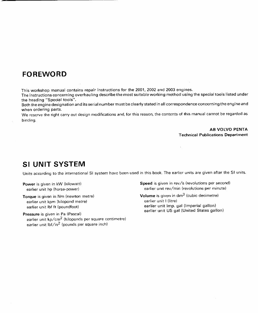
FOREWORD This workshop manual contains repair instructions for the 2001, 2002 and 2003 engines . The instructions concerning overhauling describe the most suitable working method using the special tools listed under the heading "Special tools" . Both the engine designation and its serial number must be clearly stated in all correspondence concerning the engine and when ordering parts . We reserve the right to carry out design modifications and, for this reason, the contents of this manual cannot be regarded as binding . SI UNIT SYSTEM Power is given in kW (kilowatt) Speed is given in rev/s (revolutions per second) earlier unit hp (horse-power) earlier unit rev/min (revolutions per minute) Torque is given in Nm (newton metre) Volume is given in dm 3 (cubic decimetre) earlier unit kpm (kilopond metre) earlier unit l (litre) earlier unit lbf ft (poundfoot) earlier unit Imp. gal (Imperial gallon) earlier unit US gal (United States gallon) Pressure is given in Pa (Pascal) earlier unit kp/cm 2 (kiloponds per square centimetre) earlier unit Ibf/in 2 (pounds per square inch) AB VOLVO PENTA Technical Publications Department Units according to the international SI system have been used in this book . The earlier units are given after the SI units .
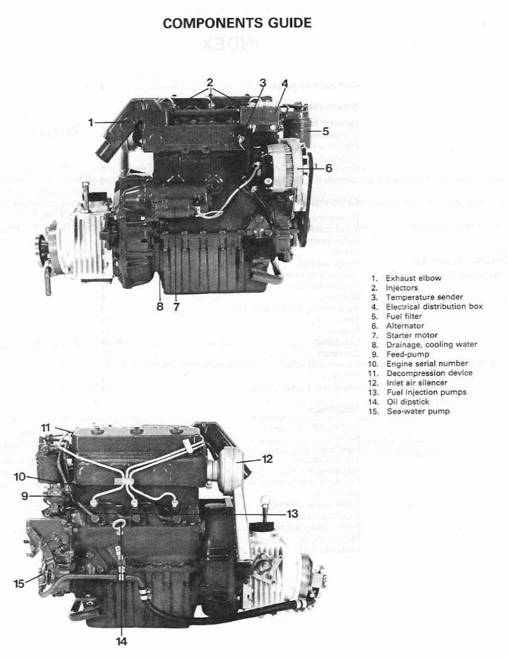
COMPONENTS GUIDE 8 1 . Exhaust elbow 2. Injectors 3 . Temperature sender 4. Electrical distribution box 5. Fuel filter 6. Alternator 7. Starter motor 8. Drainage, cooling water 9. Feed-pump 10 . Engine serial number 11 . Decompression device 12 . Inlet air silencer 13. Fuel injection pumps 14 . Oil dipstick 15 . Sea-water pump
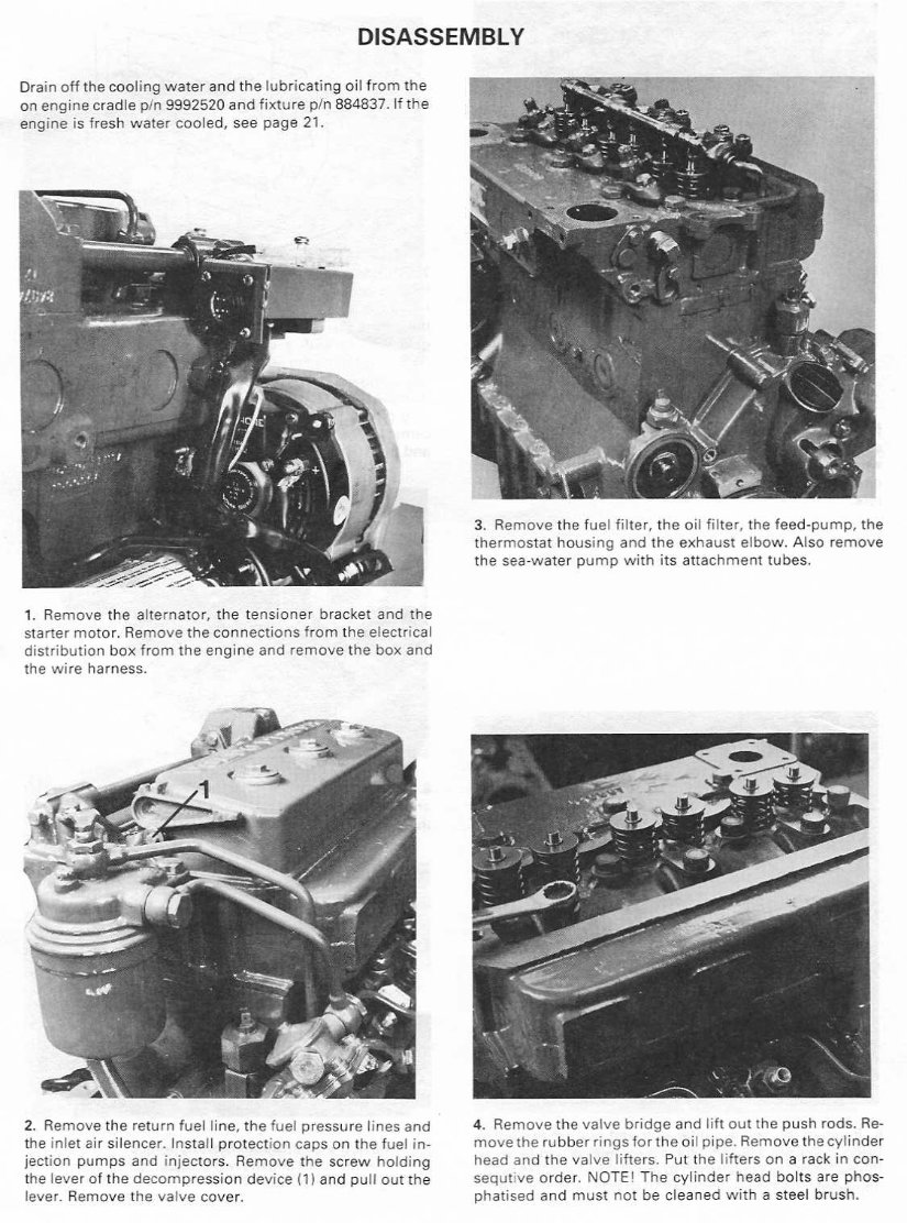
Drain off the cooling water and the lubricating oil from the on engine cradle p/n 9992520 and fixture p/n 884837 . If the engine is fresh water cooled, see page 21 . 1 . Remove the alternator, the tensioner bracket and the starter motor . Remove the connections from the electrical distribution box from the engine and remove the box and the wire harness . 2 . Remove the return fuel line, the fuel pressure lines and the inlet air silencer . Install protection caps on the fuel injection pumps and injectors . Remove the screw holding the lever of the decompression device (1) and pull out the lever . Remove the valve cover . DISASSEMBLY 3 . Remove the fuel filter, the oil filter, the feed-pump, the thermostat housing and the exhaust elbow . Also remove the sea-water pump with its attachment tubes . 4 . Remove the valve bridge and lift out the push rods . Remove the rubber rings fortheoil pipe . Remove the cylinder head and the valve lifters . Put the lifters on a rack in consecutiveorder, NOTE!Thecylinderheadboltsarephosphatisedandmustnot becleanedwithasteelbrush.
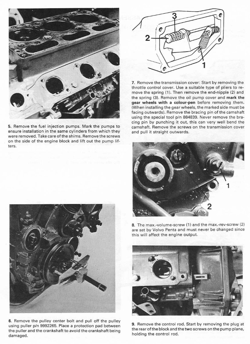
5 . Remove the fuel injection pumps . Mark the pumps to ensure installation in the same cylinders from which they were removed . Take care of the shims . Remove the screws on the side of the engine block and lift out the pump lifters . 6. Remove the pulley center bolt and pull off the pulley using puller p/n 9992265 . Place a protection pad between the puller and the crankshaft to avoid the crankshaft being damaged . 7 . Remove the transmission cover : Start by removing the throttle control cover . Use a suitable type of pliers to remove the spring (1) . Then remove the end-nipple (2) and the spring (3) . Remove the oil pump cover and mark the gear wheels with a colour-pen before removing them . (When installing the gear wheels, the marked side must be facing outwards) . Remove the bracing pin of the camshaft using the special tool p/n 884839 . Never remove the bracing pin by punching it out, this can very well bend the camshaft . Remove the screws on the transmission cover and pull it straight outwards . 8 . The max .-volume-screw (1) and the max .-rev-screw (2) are set by Volvo Penta and must never be changed since this will affect the engine output . 9 . Remove the control rod . Start by removing the plug at the rearof the block and thetwo screws on the pump plane, holding the control rod .
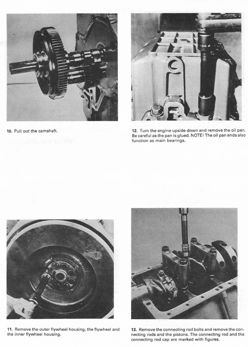
10 . Pull out the camshaft . 11 . Remove the outer flywheel housing, the flywheel and the inner flywheel housing . 12 . Turn the engine upside down and remove the oil pan . Be careful as the pan is glued . NOTE! The oil pan ends also function as main bearings . 13 . Remove the connecting rod bolts and remove the connecting rods and the pistons . The connecting rod and the connecting rod cap are marked with figures .
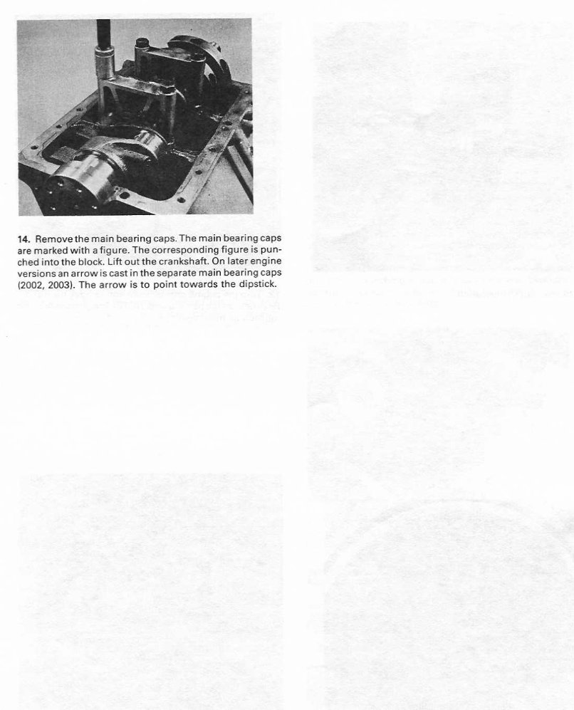
14 . Remove the main bearing caps . The main bearing caps are marked with a figure . The corresponding figure is punched into the block . Lift out the crankshaft . On later engine versions an arrow is cast in the separate main bearing caps (2002, 2003) . The arrow is to point towards the dipstick.
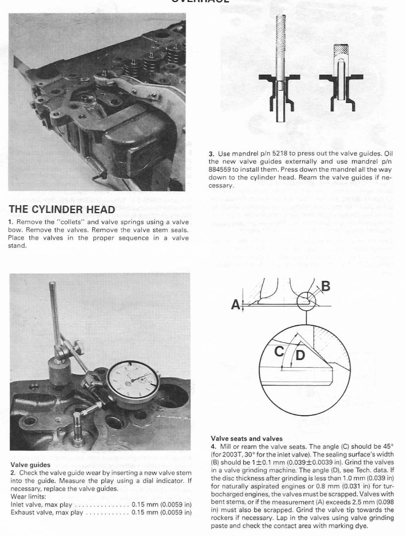
THE CYLINDER HEAD 1. Remove the "collets" and valve springs using a valve bow . Remove the valves . Remove t he valve stem seals . Place the valves in the proper sequence in a valve stand . Valve guides 2 . Check the valve guide wear by inserting anew valve stem into the guide. Measure the play using a dial indicator . If necessary, replace the valve guides . Wear limits : Inlet valve, max play . . . . . . . . . . . . . . . 0 .15 mm (0.0059 in) Exhaust valve, max play . . . . . . . . . . . . 0 .15 mm (0 .0059 in) 3 . Use mandrel p/n 5218 to press out the valve guides . Oil the new valve guides externally and use mandrel p/n 884559 to install them . Press down the mandrel all the way down to the cylinder head . Ream the valve guides if necessary . Valve seats and valves 4 . Mill or ream the valve seats . The angle (C) should be 45° (for 2003T, 30° for the inlet valve). The sealing surface's width (B) should be 1 ±0 .1 mm (0 .039±0 .0039 in) . Grind the valves in a valve grinding machine . The angle (D), see Tech . data . If the disc thickness after grinding is less than 1 .0 mm (0 .039 in) for naturally aspirated engines or 0 .8 mm (0.031 in) for turbocharged engines, the valves must be scrapped . Valves with bent stems, or if the measurement (A) exceeds 2 .5 mm (0 .098 in) must also be scrapped . Grind the valve tip towards the rockers if necessary . Lap in the valves using valve grinding paste and check the contact area with marking dye .
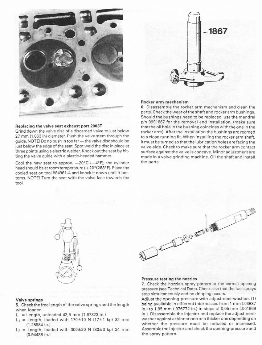
Replacing the valve seat exhaust port 2003T Grind down the valve disc of a discarded valve to just below 27 mm (1 .063 in) diameter . Push the valve stem through the guide . NOTE! Do not push in too far- the valve disc should be just below the edge of the seat . Spot weld the disc in place at three points using a electric welder . Knockout the seat by hitting the valve guide with a plastic-headed hammer . Cool the new seat to approx . -20°C (-4°F); the cylinder head should beat room temperature (+ 20°0168°F) . Place the cooled seat on tool 884961-4 and knock it down until it bottoms . NOTE! Turn the seat with the valve face towards the tool . Valve springs 5 . Checkthe free length of the valve springs and the length when loaded . L= Length, unloaded 42,5 mm (1 .67323 in .) L1= Length, loaded with 170±10 N (17±1 kp) 32 mm (1 .25984 in .) L 2 = Length, loaded with 300±20 N (30±3 kp) 24 mm (0 .94488 in .) Rocker arm mechanism 6 . Disassemble the rocker arm mechanism and clean the parts . Check the wear of the shaft and rockerarm bushings. Should the bushings need to be replaced, usethe mandrel p/n 9991867 for the removal and installation, (make sure that the oil hole in the bushing coincides with the one in the rocker arm) . After the installation the bushings are reamed to a close running fit. When installing the rockerarm shaft, it must be turned so that the lubrication holes are facing the valve-side . Check to make sure that the rocker arm contact surface againstthe valve is concave. Minor adjustments are made in a valve grinding machine . Oil the shaft and install the parts . Pressure testing the nozzles 7 . Check the nozzle's spray pattern at the correct opening pressure (see Technical Data) . Check also that the fuel sprays stop simultaneously and no dripping occurs . Adjust the opening-pressure with adjustment-washers (1) being available in different thicknesses from 1 mm U3937 in .) to 1,95 mm ( .076772 in .) in steps of 0,05 mm ( .001969 in .) . Disassemble the injector and replace the adjustment-washer againstathinneroneorathickeronedependingon whether the pressure must be reduced or increased . Assemble the injector and check the opening-pressure and the spray-pattern .
This factory service repair manual is designed for the Volvo Penta 2001 2002 2003 2003T Marine Engines. It provides detailed illustrations and step-by-step instructions, making it suitable for both do-it-yourself enthusiasts and experienced mechanics. The manual offers comprehensive guidance for the complete disassembly of the machine, including disassembly of the cylinder head, transmission, piston, piston rods, flywheel, crankshaft, camshaft, overhaul, valve components, rocker arm mechanism, injector sleeve, injectors, feed-pump, thermostat, sea-water pump, and more.
The manual is available in PDF format, compatible with all versions of Windows and Mac operating systems. It includes information on adjusting valve clearance, checking injection angle, 2003 Turbo, fresh water cooling, electrical system, fault tracing scheme, special tools, technical data, and more. This comprehensive resource is instantly accessible, allowing users to print any necessary pages. The Volvo Penta 2001 2002 2003 2003T Marine Engines Service Repair Workshop Manual is an invaluable asset for maintaining the proper functioning of your vehicle.