

Volvo Penta MD5A Marine Diesel Engine Workshop Manual
What's Included?
Fast Download Speeds
Online & Offline Access
Access PDF Contents & Bookmarks
Full Search Facility
Print one or all pages of your manual
Publ. No. 3061
Dec. 1975
WORKSHOP MANUAL
MD5A
Marine diesel engine
ENGINE UNIT

FOREWORD
This workshop manual contains repair instructions for the MD5A marine diesel engine. The instructions
concerning overhauling describe the most suitable working method to be used with the special tools listed under
the heading “Special tools”.
Both the engine designation and its serial number must be clearly stated in all correspondence concerning the
engine and when ordering spare parts. We reserve the right to carry out design modifications and, for this
reason, the contents of this manual cannot he regarded as binding.
NEW UNITS OF MEASUREMENT
Technicians have long since tried to establish an internationally standardized system of
measurements. In 1960 a decision was made to use a system called SI (Systéme International
d’Unites). To a large extent, this system is based on earlier systems but the units have been
made uniform so that no conversions are necessary.
The SI-system is now being applied within industry in Europe, This manual contains the new SI-
units. The units used previously however, are also stated but in brackets.
The new units are:
Output is slated in kW (kilowatts)
earlier unit h.p. (horsepower)
Torque is stated in NM (Newton-metres)
earlier unit kpm (kilopond-metres)
Engine speed is stated in r/s (revolutions per second)
earlier unit r.p.m. (revolutions per minute)
Displacement and volumes are stated in dm
3 (
cubic decimetres)
earlier unit l (litres)
Pressure is stated in Pa (Pascal)
earlier unit kp/cm
2
(kiloponds per square centimetre).
Reproduction permitted if source quoted

CONTENTS
Presentation 2
Dismantling
Electrical system, thermostat housing cylinder head 3
Flywheel, fuel injector pump 4
Oil pump, transmission cover, governor 5
Lubricating oil pump, camshaft, cylinder 6
Crankshaft, cylinder liner, camshaft bearing 7
Overhauling
Lubricating oil pump, sea-water pump 7 – 9
Feed pump 9 – 11
Fuel filter, crankshaft 11
Centrifugal governor, piston 12 – 13
Valve guides, nozzle sleeve 14 – 15
Valves, valve seats, rocker mechanism, injector 15 – 16
Hand start mechanism, camshaft 17
Assembling
Cylinder liner, crankshaft 18
Cylinder, camshaft, governor 19
Lubricating oil pump, transmission cover 20
Adjustment of control rod travel, assembling
flywheel cover 20 – 21
Oil sump, cylinder head, feed cover 22
Fuel filter, injector, thermostat 22
Flywheel, generator, valve adjustment 24
Checking injection angle 25
Bleeding the fuel system, electrical system 26
Wiring diagram 27
Fault-tracing system 28
Special tools 29
Technical data 30 – 33
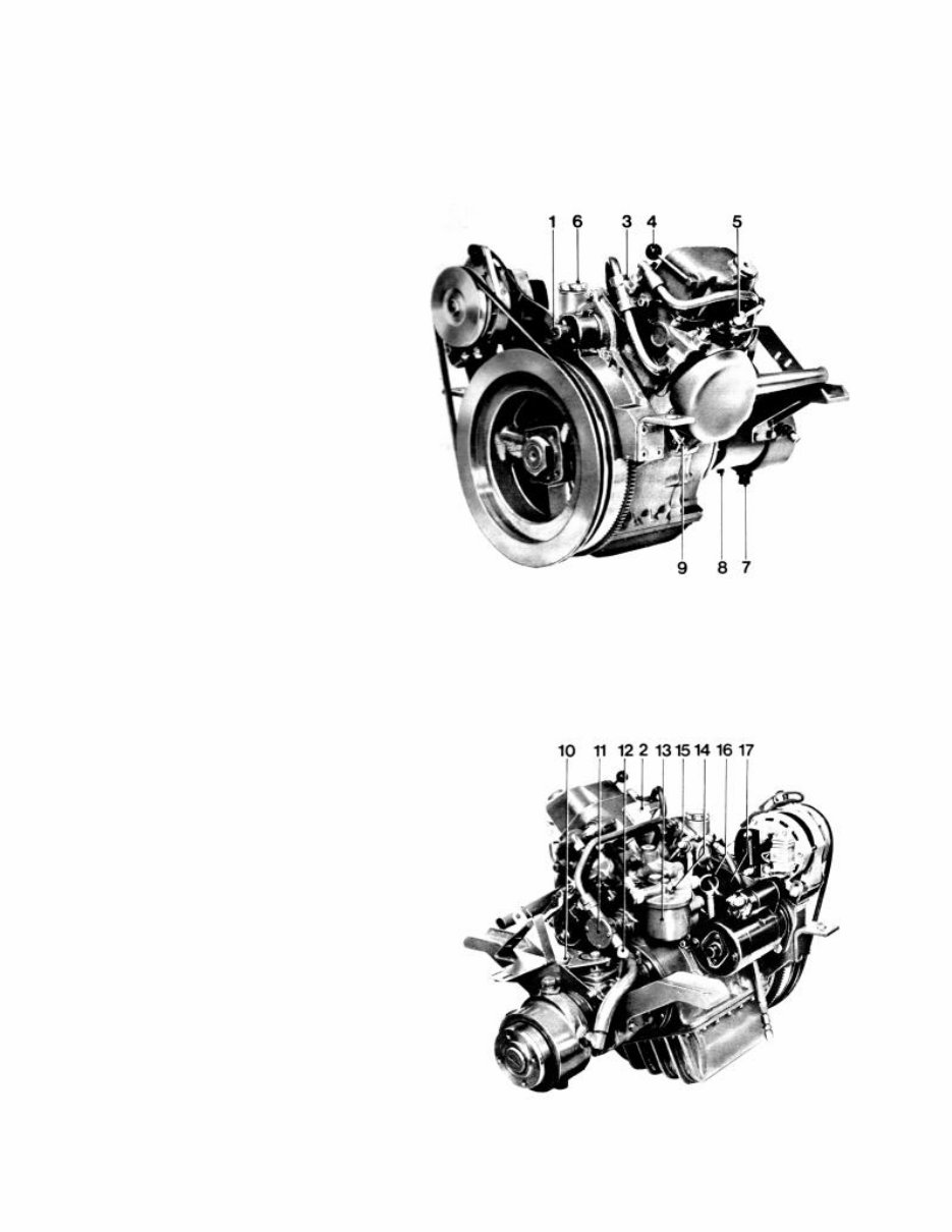
Presentation
1. Connection for hand start
2. Fuse box
3. Thermostat housing
4. Decompression lever
5. Injector
6. Oil filler Cap, engine
7. Water drain tap, gearbox
8. Oil drain plug, gearbox
9. Water drain tap, engine
10. Oil filler, gearbox
11. Sea-water pump
12. Dipstick, gearbox
13. Fuel filter
14. Bleed screw
15. Hand pump, fuel
16. Dipstick, engine
17. Oil filter
2
Repair instructions
Dismantling
1. Drain the cooling water and the oil from the engine. Clean
externally afterwards. Loosen the water hose between the
gearbox and the sea -water pump and remove the gearbox.
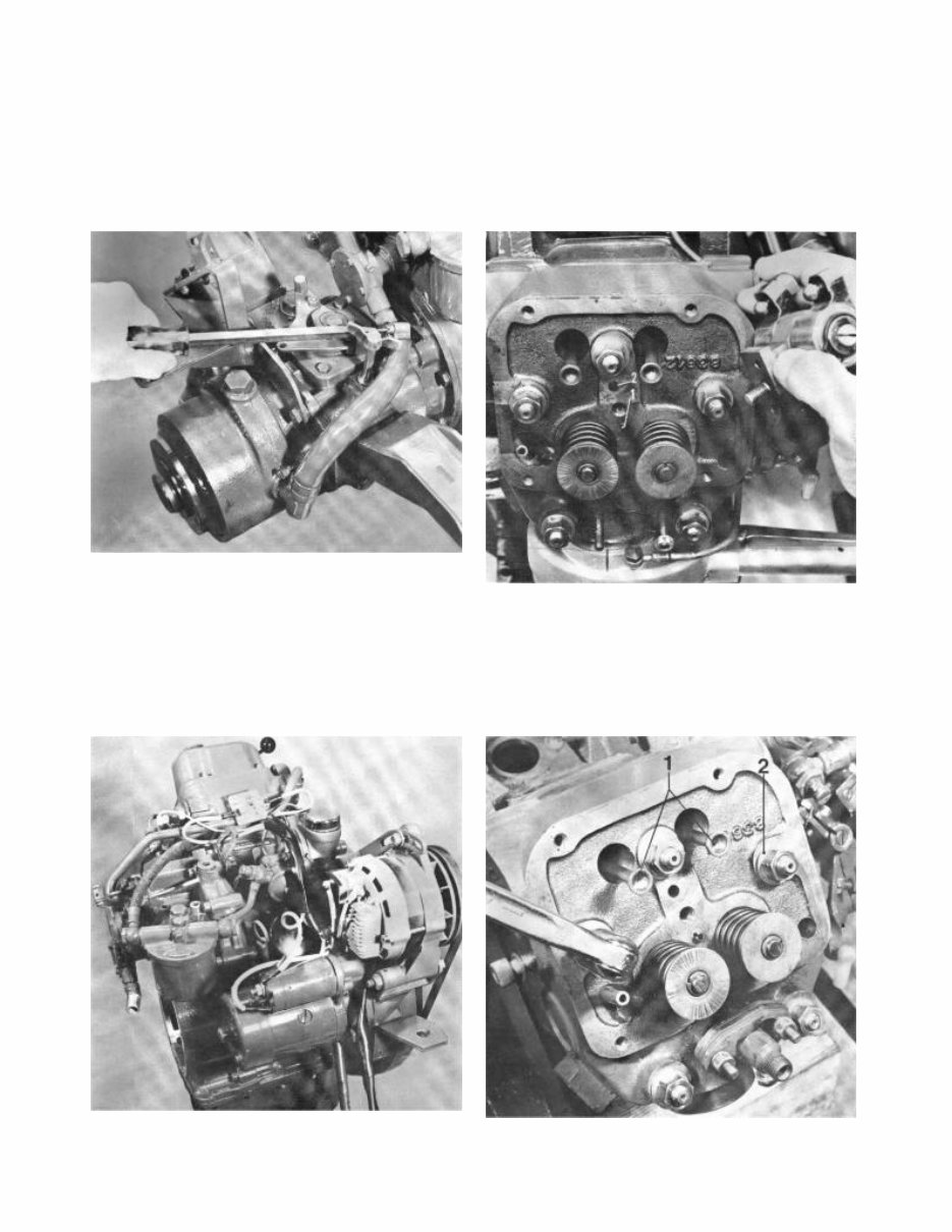
3. Remove the rocker cover and the fuel pipe between the
pump and the injector and unscrew the rocker gear. Note!
Pull the rocker gear straight up since it is centred with a
guide pin 1. The other hole 2 is an oil channel.
2. Remove the generator and its drive belt, starter motor,
fuel filter and fuel pump with the drain-off pipe (be careful of
fuel spillage), coolant water pump with hose and thermostat
housing, dipstick, temperature and oil pressure sensors.
Unscrew and discard the oil filter.
4. Remove the push-rods 1, remove the cylinder head and
the cylinder head gasket. Take care of the washers 2 under
the nuts.
3
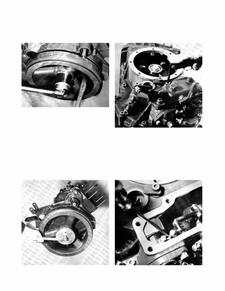
5. Remove the flywheel nuts. Spanner jaw width 55 mm
(2 5/32”). Use a wooden shaft or something similar as a
counter force in the flywheel spokes.
7. Remove the cover for the injection pump. Note! The
bracket for the cold start is fixed with one of the screws.
Take care of the spring under the cover.
6. Fit tool 884078 to the flywheel. Afterwards screw in the
centre screw on the tool until the flywheel loosens.
8. Prise the lower ball joint free from the pump with a
screwdriver.
4
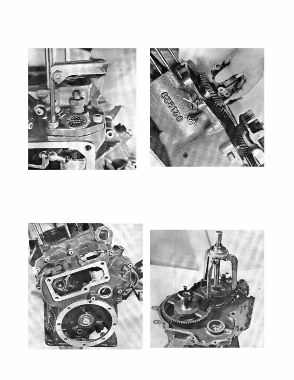
9. Remove the pump screws. Position the ball in the centre
and remove the pump.
11. Remove the governor by loosening the hexagonal set
screw (1), the governor and the gear wheel can then be
withdrawn.
10. Remove the sump and then the transmission cover (13
screws). The lifting eye is fixed one of the screws. The cover
is centralised by guide pins.
12. Remove the screw and the locking washer for the
gearbox drive flange on the crankshaft and remove the
flange with a puller. (Use counter force.) Remove the key
afterwards.
5
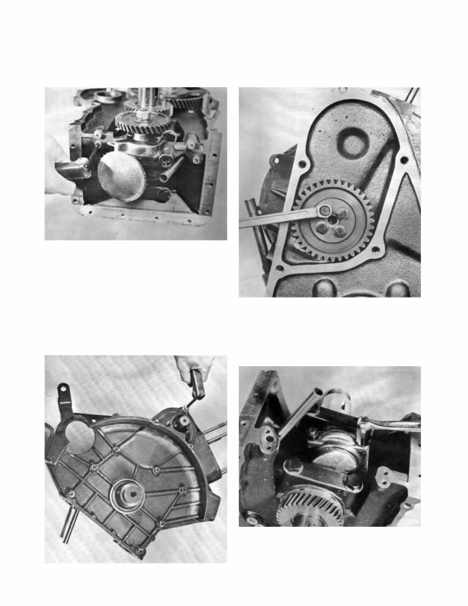
13. Remove the lubricating oil pump. Discard the gasket. 15. Remove the gearwheel on the camshaft’s flywheel side
(4 screws). Then remove the camshaft and the gearwheel.
14. Remove the cover (flywheel side), 10 screws. The cover
is centred with guide pins. The screws by the guide pins are
fitted with thick washers.
16. Mark and remove the bearing cap on the crankshaft and
carefully knock out the piston through the cylinder.
6
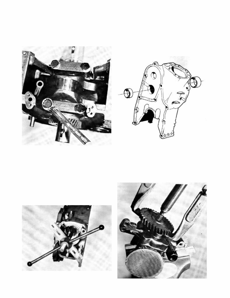
19. Bearing replacement. Press out the camshaft bearings if
they are damaged or if the wear is too great (see technical
data). Clean the bearing housings and ensure that the oil
channels are clean. Press in the new bearings so that the oil
holes face the corresponding oil channels in the block. When
the bearings are pressed in position they are to be reamed
(see technical data).
17. Remove the main bearing caps. Take care of the axial
thrust bearings 1 on the transmission side. Lift the crankshaft
out and the bearing shells afterwards and then the axial
bearing halves.
18. Mark the cylinder liner’s position in the cylinder so that
the same position can be obtained during assembly.
Remove the cylinder liner. Use tool 884551. Use the long
screw and its nut from the tool 884231 (MD21-MD32). See
page 29 Special tools. Discard the 0-ring. Afterwards remove
the 0-rings in the block which provide a seal for the cylinder
liner and then remove the valve lifters. Wash all the parts
and replace those damaged.
Oilpump
20. Remove the gearwheel’s nuts and pull off the gearwheel
with a puller. The gearwheel sits on a key, take care of this
key.
7
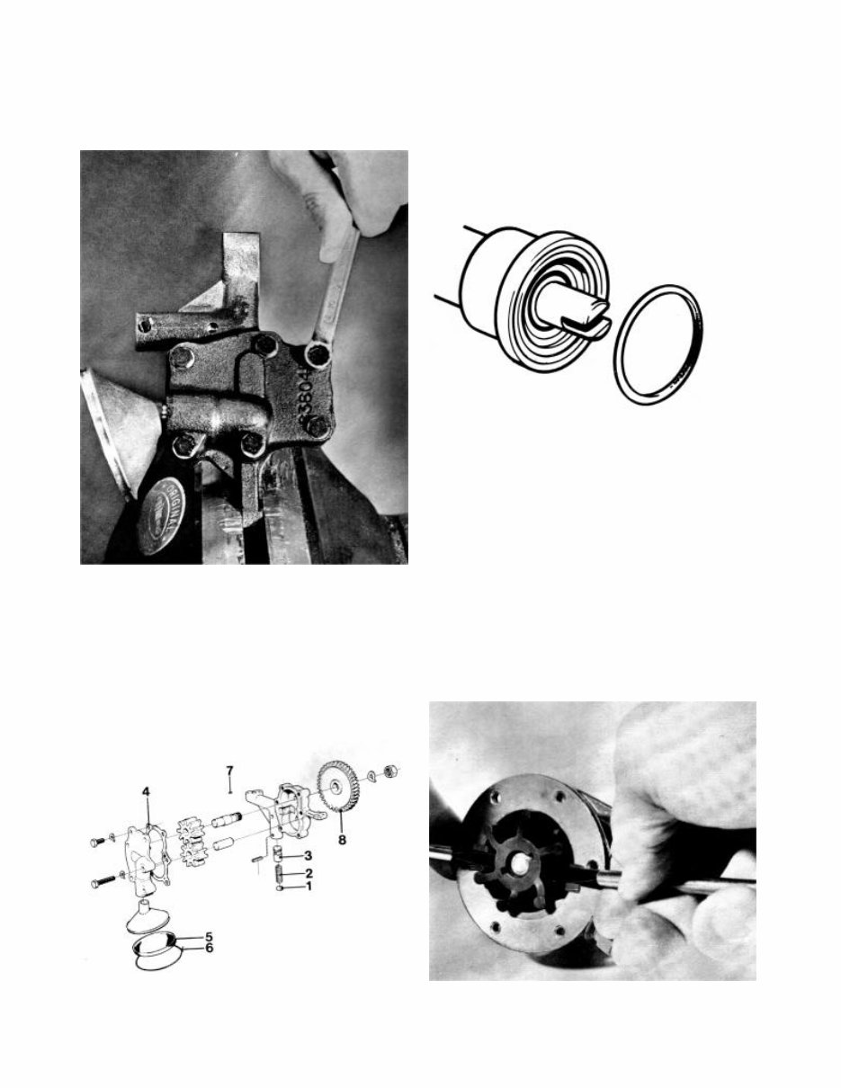
21. Remove the steel wire which holds the filter. Remove
and clean the wire gauze thoroughly. Afterwards remove the
six screws which hold the cover in position. Discard the
gasket.
Overhauling the sea-water pump
23. The sea-water pump is a round flange type pump which
means that it can be fitted in a position best suited to the
coolant water hoses. The new pump is fitted with an 0-ring
which forms a seal against the engine.
22. Remove the gearwheel from the housing. Remove the
split pin for the reduction valve. Remove washer 1, spring 2
and piston 3. Clean and replace damaged parts. Assemble
the lubricating oil pump in the reverse order. Note! Fit a new
gasket 4 between the housing and the cover. Fix the wire
mesh 5 in position with the steel wire 6 and finally lay the key
in position and tighten the gearwheel 7.
24. Remove the cover (6 screws). Change the impeller with
the help of two screwdrivers or something similar. Note!
Protect the edges of the pump housing. See the figure. Prise
out the impeller with the screwdrivers so far that the screw
becomes visible.
8
You're Reading a Preview
What's Included?
Fast Download Speeds
Online & Offline Access
Access PDF Contents & Bookmarks
Full Search Facility
Print one or all pages of your manual
$27.99
$36.99
Viewed 39 Times Today


Secure transaction
What's Included?
Fast Download Speeds
Online & Offline Access
Access PDF Contents & Bookmarks
Full Search Facility
Print one or all pages of your manual
$27.99
$36.99
If you own a Volvo Penta MD5A Marine Diesel Engine, this comprehensive service repair manual is essential for all your maintenance and repair needs. It provides detailed instructions and step-by-step diagrams for all workshop procedures, making it valuable for both professional mechanics and DIY enthusiasts.
This manual is in PDF format, allowing for easy printing of information and notes for quick reference.
It is suitable for the following model:
- Volvo Penta MD5A Marine Diesel Engine
The service repair manual covers the following:
- Presentation
- Dismantling
- Overhauling
- Assembling
Product Details:
- File Format: PDF
- Compatible: All Versions of Windows & Mac
- Language: English
- Printable: Without any restriction
- Delivery: Link will appear on the checkout page after payment is complete
- Requirements: Adobe Reader
By purchasing and downloading this manual, you can save money and time, as there is no need to pay extra costs or wait for delivery.


