

VOLVO PENTA AQ131 AQ151 AQ171 Marine Engine Workshop Repair Manual
What's Included?
Fast Download Speeds
Online & Offline Access
Access PDF Contents & Bookmarks
Full Search Facility
Print one or all pages of your manual

Engine
230, 250, 251DOHC
AQ131, AQ151, AQ171
Workshop Manual
2(0)
C


1
Safety Precautions .............................................................................. 2
General information ............................................................................ 5
Repair instructions ............................................................................. 6
Presentation ........................................................................................ 8
Trouble-shooting Scheme .................................................................. 11
1. Overhaul Data ............................................................................... 12
2. Special Tools ................................................................................ 20
3. Electrical System ......................................................................... 23
Wiring Diagram AQ131, AQ151, 230, 250 Alt. 1. ........................ 24
Wiring Diagram 230, 250 Alt. 2 .................................................. 26
Wiring Diagram AQ171, 251DOHC Alt.1. .................................. 28
Wiring Diagram 251DOHC Alt. 2 ............................................... 30
4A. Fuel System .................................................................................. 32
Trouble shooting and Remedies Fuel System ............................ 32
Overhauling and checking the carburetor ................................... 33
4B. Renix Ignition System .................................................................. 38
Trouble-shooting and repair ignition system 251DOHC, AQ171 38
4C. Cylinder Head ............................................................................... 44
Removal of teh external components ......................................... 44
4D. Cooling System ............................................................................ 48
Overhauling the heat exchanger ................................................. 48
Overhauling the sea water pump ................................................ 49
Check the thermostat .................................................................. 49
4E. Overhauling the valve system ..................................................... 50
Overhauling the valve system 230, 250, AQ131, AQ151 ........... 50
Adjusting the valves 230, 250, AQ131, AQ151 .......................... 59
Valve system 251DOHC, AQ171. Technical Description ........... 61
Overhauling the valve system 251DOHC, AQ171 ...................... 63
4F. Installing the toothed belt ........................................................... 71
Installing the toothed belt 230, 250, AQ131, AQ151 ...................... 71
Installing the toothed belt 251DOHC, AQ171 ................................. 73
4G. Installing the external components of the Cylinder Head ........ 74
5. Cylinder Block .............................................................................. 78
5A. Removing the external components ........................................... 78
5B. Overhauling the Crank Assembly ............................................... 80
The lubricating oil pump Overhauling .......................................... 87
5C. Installing the external components ............................................ 93
Overhauling the oil cooler 250, 251DOHC, AQ151, AQ171 ........ 95
Workshop Manual
Index
230, 250, 251DOHC,
AQ131, AQ151, AQ171
2
Safety Precautions
Check that the warning or information decals on
the product are always clearly visible. Replace
decals that have been damaged or painted over.
Engine with turbocharger: Never start the engine
without installing the air cleaner (ACL). The ro-
tating compressor in the Turbo can cause ser-
ious personal injury. Foreign objects entering
the intake ducts can also cause mechanical
damage.
Never use start spray or similar to start the en-
gine. The starter element may cause an explo-
sion in the inlet manifold. Danger of personal in-
jury.
Avoid opening the filler cap for engine coolant
system (freshwater cooled engines) when the
engine is still hot. Steam or hot coolant can
spray out. Open the coolant filler cap carefully
and slowly to release pressure before removing
the cap completely. Take great care if a cock,
plug or engine coolant line must be removed
from a hot engine. It is difficult to anticipate in
which direction steam or hot coolant can spray
out.
Hot oil can cause burns. Avoid skin contact with
hot oil. Ensure that the lubrication system is not
under pressure before commencing work on it.
Never start or operate the engine with the oil
filler cap removed, otherwise oil could be
ejected.
Stop the engine and close the sea cock before
carrying out operations on the engine cooling
system.
Only start the engine in a well-ventilated area. If
operating the engine in an enclosed space, en-
sure that exhaust gases and crankcase ventila-
tion emissions are ventilated out of the working
area.
Introduction
This Workshop Manual contains technical data, de-
scriptions and repair instructions for Volvo Penta prod-
ucts or product versions contained in the contents list.
Ensure that the correct workshop literature is being
used.
Read the safety information and the Workshop
Manual “General Information” and “Repair Instruc-
tions” carefully before starting work.
Important
In this book and on the engine you will find the follow-
ing special warning symbols.
WARNING! If these instructions are not fol-
lowed there is a danger of personal injury, ex-
tensive damage to the product or serious me-
chanical malfunction.
IMPORTANT! Used to draw your attention to
something that can cause damage, product
malfunction or damage to property.
NOTE! Used to draw your attention to important in-
formation that will facilitate work or operations.
Below is a summary of the risks and safety precau-
tions you should always observe or carry out when
operating or servicing the engine.
Immobilize the engine by turning off the power
supply to the engine at the main switch (switch-
es) and lock it (them) in the OFF position before
starting work. Set up a warning notice at the en-
gine control point or helm.
Generally, all servicing should be carried out
with the engine switched off. Some work (carry-
ing out certain adjustments for example) re-
quires the engine to be running. Approaching a
running engine is dangerous. Loose clothing or
long hair can fasten in rotating parts and cause
serious personal injury. If working in proximity
to a running engine, careless movements or a
dropped tool can result in personal injury. Avoid
burns. Take precautions to avoid hot surfaces
(exhausts, turbochargers, charge air pipes and
starter elements etc.) and liquids in supply lines
and hoses when the engine is running or has
been turned off immediately prior to starting
work on it. Reinstall all protective parts removed
during service operations before starting the en-
gine.
3
Always use protective goggles where there is
a danger of pieces of metal, sparks from grind-
ing, acid or other chemicals being thrown into
your eyes. Your eyes are very sensitive, injury
can lead to loss of sight!
Avoid skin contact with oil. Long-term or re-
peated contact with oil can remove the natural
oils from your skin. The result can be irritation,
dry skin, eczema and other skin problems.
Used oil is more dangerous to health than new
oil. Use protective gloves and avoid using oil-
soaked clothes and rags. Wash regularly, es-
pecially before meals. Use the correct barrier
cream to prevent dry skin and to make clean-
ing your skin easier.
Most chemicals used in products (engine and
transmission oils, glycol, petrol and diesel oil)
and workshop chemicals (solvents and paints)
are hazardous to health Read the instructions
on the product packaging carefully! Always fol-
low safety instructions (using breathing appa-
ratus, protective goggles and gloves for ex-
ample). Ensure that other personnel are not
unwittingly exposed to hazardous substances
(by breathing them in for example). Ensure
that ventilation is good. Handle used and ex-
cess chemicals according to instructions.
Be extremely careful when tracing leaks in the
fuel system and testing fuel injection nozzles.
Use protective goggles! The jet ejected from a
fuel injection nozzle is under very high pres-
sure, it can penetrate body tissue and cause
serious injury There is a danger of blood poi-
soning.
All fuels and many chemicals are inflammable.
Ensure that a naked flame or sparks cannot ig-
nite fuel or chemicals. Combined with air in
certain ratios, petrol, some solvents and hy-
drogen from batteries are easily inflammable
and explosive. Smoking is prohibited! Ensure
that ventilation is good and that the necessary
safety precautions have been taken before
carrying out welding or grinding work. Always
have a fire extinguisher to hand in the work-
place.
Store oil and fuel-soaked rags and fuel and oil
filters safely. In certain conditions oil-soaked
rags can spontaneously ignite. Used fuel and
oil filters are environmentally dangerous waste
and must be deposited at an approved site for
destruction together with used lubricating oil,
contaminated fuel, paint remnants, solvent, de-
greasing agents and waste from washing
parts.
Never allow a naked flame or electric sparks
near the batteries. Never smoke in proximity to
the batteries. The batteries give off hydrogen
gas during charging which when mixed with air
can form an explosive gas – oxyhydrogen.
This gas is easily ignited and highly volatile.
Incorrect connection of the battery can cause
a spark which is sufficient to cause an explo-
sion with resulting damage. Do not disturb bat-
tery connections when starting the engine
(spark risk) and do not lean over batteries.
Never mix up the positive and negative battery
terminals when installing. Incorrect installation
can result in serious damage to electrical
equipment. Refer to wiring diagrams.
Always use protective goggles when charging
and handling batteries. The battery electrolyte
contains extremely corrosive sulfuric acid. If
this comes into contact with the skin, wash im-
mediately with soap and plenty of water. If bat-
tery acid comes into contact with the eyes, im-
mediately flush with copious amounts of water
and obtain medical assistance.
Turn off the engine and turn off power at main
switch(es) before carrying out work on the
electrical system.
Clutch adjustments must be carried out with
the engine turned off.

4
Use the lifting eyes mounted on the engine/re-
verse gear when lifting the drive unit.
Always check that lifting equipment is in good
condition and has sufficient load capacity to lift
the engine (engine weight including reverse
gear and any extra equipment installed).
To ensure safe handling and to avoid damaging
engine components on top of the engine, use a
lifting beam to raise the engine. All chains and
cables should run parallel to each other and as
perpendicular as possible in relation to the top
of the engine.
If extra equipment is installed on the engine al-
tering its center of gravity, a special lifting de-
vice is required to achieve the correct balance
for safe handling.
Never carry out work on an engine suspended
on a hoist.
Never remove heavy components alone, even
where secure lifting equipment such as se-
cured blocks are being used. Even where lift-
ing equipment is being used it is best to carry
out the work with two people; one to operate
the lifting equipment and the other to ensure
that components are not trapped and damaged
when being lifted. When working on-board en-
sure that there is sufficient space to remove
components without danger of injury or dam-
age.
Components in the electrical system, ignition
system (gasoline engines) and fuel system on
Volvo Penta products are designed and con-
structed to minimize the risk of fire and explo-
sion. The engine must not be run in areas
where there are explosive materials.
Always use fuels recommended by Volvo Pen-
ta. Refer to the Instruction Book. The use of
lower quality fuels can damage the engine. On
a diesel engine poor quality fuel can cause the
control rod to seize and the engine to overrev
with the resulting risk of damage to the engine
and personal injury. Poor fuel quality can also
lead to higher maintenance costs.

5
General information
About the workshop manual
This workshop manual contains technical specifica-
tion, descriptions and instructions for repairing the
standard versions of the following engines 230, 250,
251DOHC, AQ131, AQ151 and AQ171. The product
designation and number should be given in all corre-
spondence about the product.
This Workshop Manual has been developed primarily
for Volvo Penta service workshops and qualified per-
sonnel. Persons using this book are assumed to
have a grounding in marine drive systems and be
able to carry out related mechanical and electrical
work.
Volvo Penta is continuously developing their prod-
ucts. We therefore reserve the right to make
changes. All the information contained in this book is
based on product data available at the time of going
to print. Any essential changes or modifications in-
troduced into production or updated or revised ser-
vice methods introduced after the date of publication
will be provided in the form of Service Bulletins.
Replacement parts
Replacement parts for electrical and fuel systems
are subject to statutory requirements (US Coast
Guard Safety Regulations for example). Volvo Penta
Genuine parts meet these requirements. Any type of
damage which results from the use of non-original
Volvo Penta replacement parts for the product will
not be covered under any warranty provided by Vol-
vo Penta.

6
Repair instructions
The working methods described in the Service Ma-
nual apply to work carried out in a workshop. The
engine has been removed from the boat and is in-
stalled in an engine fixture. Unless otherwise stated
reconditioning work which can be carried out with
the engine in place follows the same working
method.
Warning symbols occurring in the Workshop Manual
(for their meaning see Safety information)
WARNING!
IMPORTANT!
NOTE!
are not in any way comprehensive since it is impos-
sible to predict every circumstance under which ser-
vice work or repairs may be carried out. For this rea-
son we can only highlight the risks that can arise
when work is carried out incorrectly in a well-
equipped workshop using working methods and
tools developed by us.
All procedures for which there are Volvo Penta spe-
cial tools in this Workshop Manual are carried out
using these. Special tools are developed to rational-
ize working methods and make procedures as safe
as possible. It is therefore the responsibility of any
person using tools or working methods other than
the ones recommended by us to ensure that there is
no danger of injury, damage or malfunction resulting
from these.
In some cases there may be special safety precau-
tions and instructions for the use of tools and chem-
icals contained in this Workshop Manual. These spe-
cial instructions should always be followed if there
are no separate instructions in the Workshop Man-
ual.
Certain elementary precautions and common sense
can prevent most risks arising. A clean workplace
and engine eliminates much of the danger of injury
and malfunction.
It is of the greatest importance that no dirt or foreign
particles get into the fuel system, lubrication sys-
tem, intake system, turbocharger, bearings and
seals when they are being worked on. The result
can be malfunction or a shorter operational life.
Our joint responsibility
Each engine consists of many connected systems
and components. If a component deviates from its
technical specification the environmental impact of an
otherwise good engine may be increased significantly.
It is therefore vital that wear tolerances are main-
tained, that systems that can be adjusted are adjusted
properly and that Volvo Penta Genuine Parts as used.
The engine Maintenance Schedule must be followed.
Some systems, such as the components in the fuel
system, require special expertise and special testing
equipment for service and maintenance. Some com-
ponents are sealed at the factory for environmental
reasons. No work should be carried out on sealed
components except by authorized personnel.
Bear in mind that most chemicals used on boats are
harmful to the environment if used incorrectly.
Volvo Penta recommends the use of biodegradable
degreasing agents for cleaning engine components,
unless otherwise stated in a workshop manual. Take
special care when working on-board, that oil and
waste is taken for destruction and is not accidentally
pumped into the environment with bilge water.
Tightening torques
Tightening torques for vital joints that must be
tightened with a torque wrench are listed in workshop
manual “Technical Data”: “Tightening Torques” and are
contained in work descriptions in this Manual. All tor-
ques apply for cleaned threads, screw heads and
mating surfaces. Torques apply for lightly oiled or dry
threads. If lubricants, locking fluid or sealing com-
pound are required for a screwed joint this information
will be contained in the work description and in “Tight-
ening Torques” Where no tightening torque is stated for
a joint use the general tightening torques according to
the tables below. The tightening torques stated are a
guide and the joint does not have to be tightened using
a torque wrench.
Dimension Tightening Torques
Nm lbt.ft
M5 6 4,4
M6 10 7,4
M8 25 18,4
M10 50 36,9
M12 80 59,0
M14 140 103,3

7
Tightening torques-protractor
(angle) tightening
Tightening using both a torque set-
ting and a protractor angle requires
that first the recommended torque is
applied using a torque wrench and
then the recommended angle is
added according to the protractor
scale. Example: a 90° protractor
tightening means that the joint is
tightened a further 1/4 turn in one
operation after the stated tightening
torque has been applied.
Locknuts
Do not re-use lock nuts that have been removed
during dismantling as they have reduced service life
when re-used – use new nuts when assembling or
reinstalling. For lock nuts with a plastic insert such
as Nylock
®
the tightening torque stated in the table
is reduced if the Nylock
®
nut has the same head
height as a standard hexagonal nut without plastic
insert. Reduce the tightening torque by 25% for bolt
size 8 mm or larger. Where Nylock
®
nuts are higher,
or of the same height as a standard hexagonal nut,
the tightening torques given in the table apply.
Tolerance classes
Screws and nuts are divided into different strength
classes, the class is indicated by the number on the
bolt head. A high number indicates stronger material,
for example a bolt marked 10-9 indicates a higher
tolerance than one marked 8-8. It is therefore im-
portant that bolts removed during the disassembly
of a bolted joint must be reinstalled in their original
position when assembling the joint. If a bolt must be
replaced check in the replacement parts catalogue
to make sure the correct bolt is used.
Sealants
A number of sealants and locking liquids are used on
the engines. The agents have varying properties and
are used for different types of jointing strengths,
operating temperature ranges, resistance to oil and
other chemicals and for the different materials and
gap sizes in the engines.
To ensure service work is correctly carried out it is
important that the correct sealant and locking fluid
type is used on the joint where the agents are re-
quired.
In this Volvo Penta Service Manual the user will find
that each section where these agents are applied in
production states which type was used on the engine.
During service operations use the same agent or an
alternative from a different manufacturer.
Make sure that mating surfaces are dry and free from
oil, grease, paint and anti-corrosion agent before app-
lying sealant or locking fluid. Always follow the
manufacturer’s instructions for use regarding; tempe-
rature range, curing time and any other instructions
for the product.
Tow different basic types of agent are used on the
engine and these are:
RTV agent (Room temperature vulcanizing). Use for
gaskets, sealing gasket joints or coating gaskets. RTV
agent is clearly visible when a component has been
dismantled; old RTV must be removed before the joint
is resealed.
The following RTV agents are mentioned in the Ser-
vice Manual: Loctite
®
574, Volvo Penta 840879-1,
Permatex
®
No. 3, Volvo Penta P/N 1161099-5, Perma-
tex
®
No. 77. Old sealant can be removed using methy-
lated spirits in all cases.
Anaerobic agents. These agents cure in an absence of
air. They are used when two solid parts, for example
cast components, are installed face-to-face without a
gasket. They are also commonly used to secure
plugs, threads in stud bolts, cocks, oil pressure swit-
ches and so on. The cured material is glass-like and it
is therefore colored to make it visible. Cured anaer-
obic agents are extremely resistant to solvents and
the old agent cannot be removed. When reinstalling
the part is carefully degreased and then new sealant
is applied.
The following anaerobic agents are mentioned in the
Service Manual: Loctite
®
572 (white), Loctite
®
241
(blue).
NOTE! Loctite® is the registered trademark of Loctite Corpora-
tion, Permatex® is the registered trademark of the Permatex
Corporation.
8
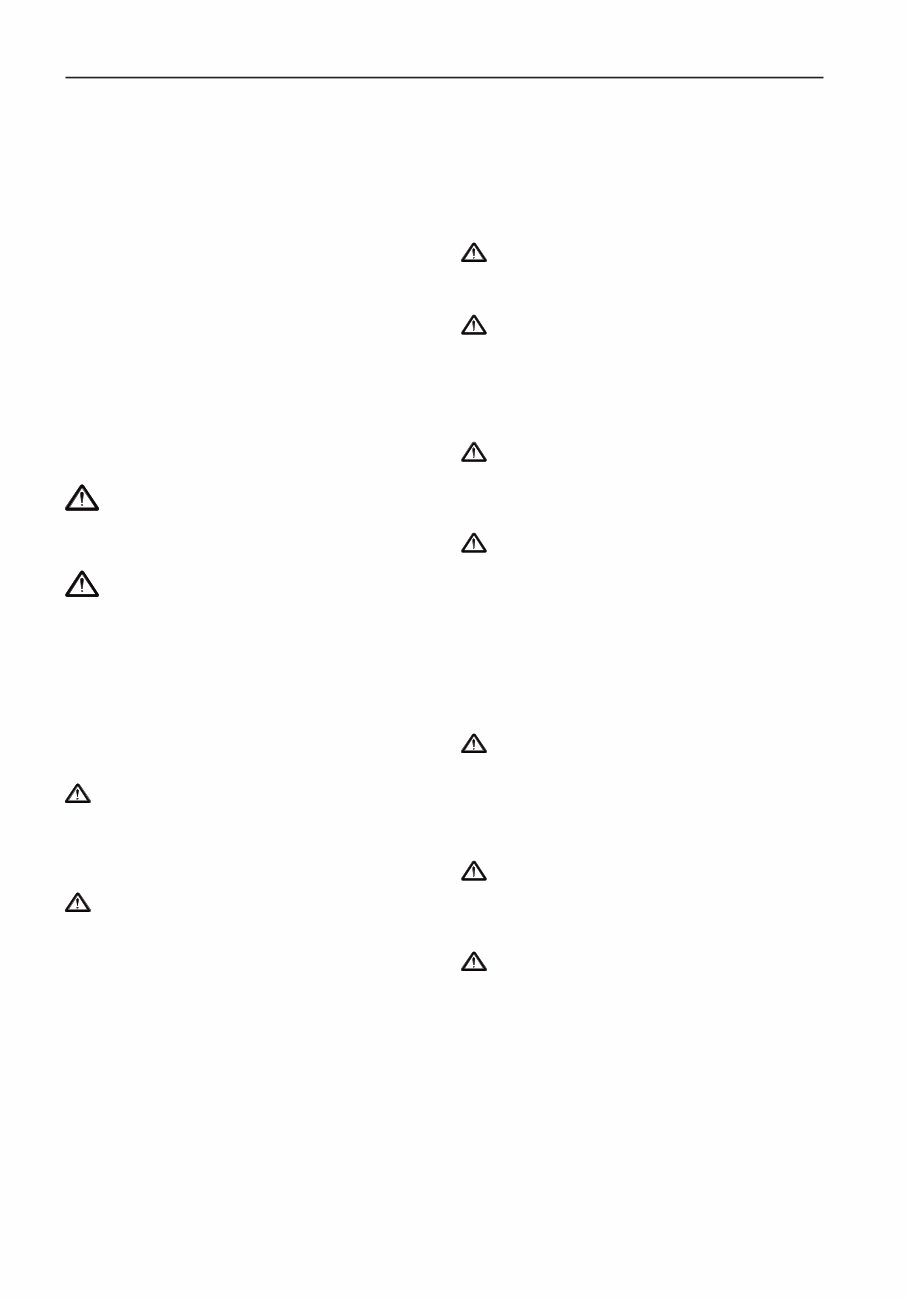
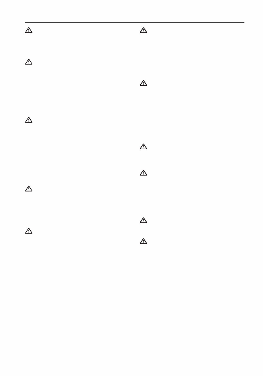
Presentation
The engines are 4 cylinder gasoline engines. All the
engines are equipped with freshwater cooling in
combination with seawater cooling. The seawater
system is powered by a direct drive impeller pump.
The thermostat controlled freshwater system is pow-
ered by a circulation pump.
The engines are manufactured with two different
product designations. During 1989 Volvo Penta be-
gan designating engines based on their cylinder dis-
placement according to the ISO norm 8665. The
older product designations of AQ131, AQ151 and
AQ171 (where the number provided an approximate
indication of output) were withdrawn. The new des-
ignation 230 replaced AQ131, 250 replaced
AQ151and 251DOHC replaced AQ171.
250, AQ151 and 251DOHC, AQ171 are equipped
with an oil cooler. 230, AQ131 has a single
carburettor and the others have twin carburettors.
The exhaust system has seawater cooled exhaust
pipes. 230, AQ131 and 250, AQ151 models have an
overhead camshaft while 251DOHC, AQ171 has
double overhead camshafts with hydraulic valve lift-
ers. 251DOHC, AQ171 is a 16 valve engine. 230,
AQ131 and 250, AQ151 models have conventional
marine ignition systems while 251DOHC, AQ171
has electronic ignition.
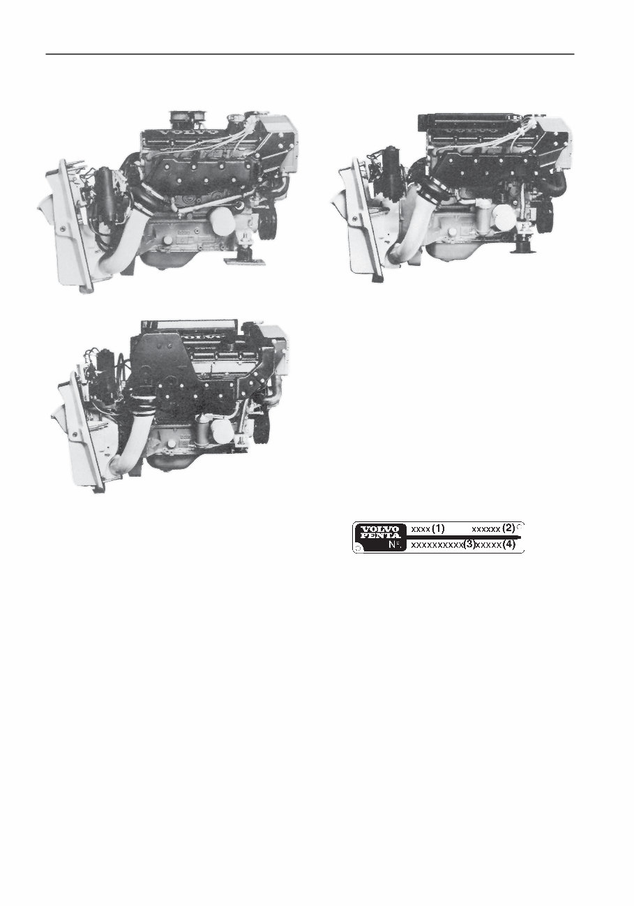
The product plate is located on the cylinder block
beside the starter motor. The product plate provides
the following information;
(1) Product designation, i.e. AQ131D
(2) Product number, i.e 867902
(3) Serial number (10 digit)
(4) Basic engine, serial number
Product plate
230, AQ131 250, AQ151
251DOHC, AQ171
You're Reading a Preview
What's Included?
Fast Download Speeds
Online & Offline Access
Access PDF Contents & Bookmarks
Full Search Facility
Print one or all pages of your manual
$35.99
$46.99
Viewed 69 Times Today


Secure transaction
What's Included?
Fast Download Speeds
Online & Offline Access
Access PDF Contents & Bookmarks
Full Search Facility
Print one or all pages of your manual
$35.99
$46.99
This workshop repair manual for the Volvo Penta AQ131, AQ151, and AQ171 marine engines is a comprehensive guide for vehicle repair, maintenance, rebuilding, refurbishing, and restoration. It is an essential resource for both professional technicians and DIY enthusiasts.
- All repair procedures are covered extensively from A-Z
- Includes high-quality photos, illustrations, and diagrams
- Compatible with Microsoft Windows 95, 98, 98SE, 2000, NT, ME, XP, Vista, and Windows 7, and also works on all Mac computers
This workshop repair manual provides easy access to complete repair procedures, allowing users to view, print, and start work without requiring advanced computer skills. Say goodbye to messy and worn-out manuals with this trusted resource.


