

Volvo Penta 3.0GS/3.0GL Marine Engine Service & Repair Manual
What's Included?
Fast Download Speeds
Online & Offline Access
Access PDF Contents & Bookmarks
Full Search Facility
Print one or all pages of your manual

Workshop Manual
Engine
3.0GS-A/B/C
3.0GL-A/B/C
C
2(0)


VPA 7743358 03-2003 i
General Information . . . . . . . . . . . . . . . . . . . 1
Engine Mechanical 3.0 Liter . . . . . . . . . . . 27
Steering System . . . . . . . . . . . . . . . . . . . . . 95
Throttle & Shift Control System . . . . . . . 117
Cooling System . . . . . . . . . . . . . . . . . . . . 125
Engine Removal and Installation . . . . . . 139
Safety . . . . . . . . . . . . . . . . . . . . . . . . . . . . . . . S

ii VPA 7743358 03-2003
NOTES
- - - - - - - - - - - - - - - - - - - - - - - - - - - - - - - - - - - - - - - - - - - - - - - - - - - - - - - - - - - - - - -
- - - - - - - - - - - - - - - - - - - - - - - - - - - - - - - - - - - - - - - - - - - - - - - - - - - - - - - - - - - - - - -
- - - - - - - - - - - - - - - - - - - - - - - - - - - - - - - - - - - - - - - - - - - - - - - - - - - - - - - - - - - - - - -
- - - - - - - - - - - - - - - - - - - - - - - - - - - - - - - - - - - - - - - - - - - - - - - - - - - - - - - - - - - - - - -
- - - - - - - - - - - - - - - - - - - - - - - - - - - - - - - - - - - - - - - - - - - - - - - - - - - - - - - - - - - - - - -
- - - - - - - - - - - - - - - - - - - - - - - - - - - - - - - - - - - - - - - - - - - - - - - - - - - - - - - - - - - - - - -
- - - - - - - - - - - - - - - - - - - - - - - - - - - - - - - - - - - - - - - - - - - - - - - - - - - - - - - - - - - - - - -
- - - - - - - - - - - - - - - - - - - - - - - - - - - - - - - - - - - - - - - - - - - - - - - - - - - - - - - - - - - - - - -
- - - - - - - - - - - - - - - - - - - - - - - - - - - - - - - - - - - - - - - - - - - - - - - - - - - - - - - - - - - - - - -
- - - - - - - - - - - - - - - - - - - - - - - - - - - - - - - - - - - - - - - - - - - - - - - - - - - - - - - - - - - - - - -
- - - - - - - - - - - - - - - - - - - - - - - - - - - - - - - - - - - - - - - - - - - - - - - - - - - - - - - - - - - - - - -
- - - - - - - - - - - - - - - - - - - - - - - - - - - - - - - - - - - - - - - - - - - - - - - - - - - - - - - - - - - - - - -
- - - - - - - - - - - - - - - - - - - - - - - - - - - - - - - - - - - - - - - - - - - - - - - - - - - - - - - - - - - - - - -
- - - - - - - - - - - - - - - - - - - - - - - - - - - - - - - - - - - - - - - - - - - - - - - - - - - - - - - - - - - - - - -
- - - - - - - - - - - - - - - - - - - - - - - - - - - - - - - - - - - - - - - - - - - - - - - - - - - - - - - - - - - - - - -
- - - - - - - - - - - - - - - - - - - - - - - - - - - - - - - - - - - - - - - - - - - - - - - - - - - - - - - - - - - - - - -
- - - - - - - - - - - - - - - - - - - - - - - - - - - - - - - - - - - - - - - - - - - - - - - - - - - - - - - - - - - - - - -
- - - - - - - - - - - - - - - - - - - - - - - - - - - - - - - - - - - - - - - - - - - - - - - - - - - - - - - - - - - - - - -
- - - - - - - - - - - - - - - - - - - - - - - - - - - - - - - - - - - - - - - - - - - - - - - - - - - - - - - - - - - - - - -
- - - - - - - - - - - - - - - - - - - - - - - - - - - - - - - - - - - - - - - - - - - - - - - - - - - - - - - - - - - - - - -
- - - - - - - - - - - - - - - - - - - - - - - - - - - - - - - - - - - - - - - - - - - - - - - - - - - - - - - - - - - - - - -
- - - - - - - - - - - - - - - - - - - - - - - - - - - - - - - - - - - - - - - - - - - - - - - - - - - - - - - - - - - - - - -
- - - - - - - - - - - - - - - - - - - - - - - - - - - - - - - - - - - - - - - - - - - - - - - - - - - - - - - - - - - - - - -
- - - - - - - - - - - - - - - - - - - - - - - - - - - - - - - - - - - - - - - - - - - - - - - - - - - - - - - - - - - - - - -
VPA 7743358 03-2003 iii
Model Identification
All stern drive system components must be matched for either single
or dual engine installations. Failure to properly match engine, transom
bracket and sterndrive will result in poor boat performance, and risk
damage to engine and drive because of incorrect drive gear ratio.
Model identification is located on the engine, and MUST correspond
with the transom shield and sterndrive numbers as listed in the Prod-
uct Matrix sheet available separately.
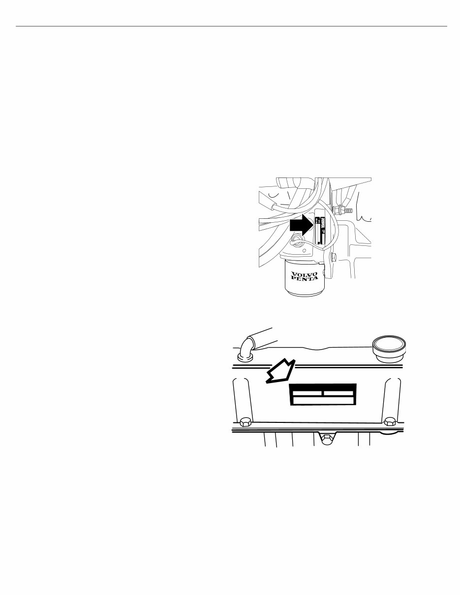
Engine Model Number
All Engine Models
GS, and GL Engines
23282
DR1145
iv VPA 7743358 03-2003
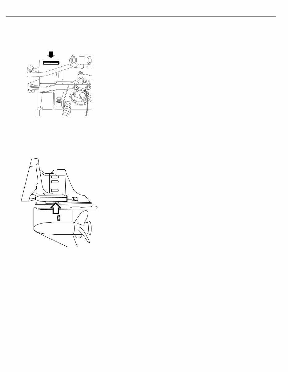
Transom Shield Model Number Location
Sterndrive Model Number Location
SX and DP-S
DR2058
DR4957

General Information
VPA 7743358 03-2003 1
Section 1: General Information
Tuning the Engine . . . . . . . . . . . . . . . . . . . . . . . . . . . . . . . . . . . . . . 3
Intake Manifold Vacuum Testing . . . . . . . . . . . . . . . . . . . . . . . . . . 6
Gasoline Requirements . . . . . . . . . . . . . . . . . . . . . . . . . . . . . . . . . . 8
Gasoline Containing Alcohol . . . . . . . . . . . . . . . . . . . . . . . . . . . . . 8
Crankcase Oil . . . . . . . . . . . . . . . . . . . . . . . . . . . . . . . . . . . . . . . . . . 9
Power Steering . . . . . . . . . . . . . . . . . . . . . . . . . . . . . . . . . . . . . . . . 10
Steering System Lubrication . . . . . . . . . . . . . . . . . . . . . . . . . . 11
Power Trim/Tilt Fluid Level . . . . . . . . . . . . . . . . . . . . . . . . . . . . . . 11
Off-Season Storage . . . . . . . . . . . . . . . . . . . . . . . . . . . . . . . . . . . . 11
Preparation for Boating After Storage . . . . . . . . . . . . . . . . . . . . . 14
Engine Break-in . . . . . . . . . . . . . . . . . . . . . . . . . . . . . . . . . . . . . . . 15
Submerged Engine or Water Ingestion in Cylinders . . . . . . . . . 16
20-Hour Check . . . . . . . . . . . . . . . . . . . . . . . . . . . . . . . . . . . . . . . . 17
Positive Closed Ventilation System . . . . . . . . . . . . . . . . . . . . . . . 18
Troubleshooting - System Isolation . . . . . . . . . . . . . . . . . . . . . . . 19
Engine Troubleshooting Guides . . . . . . . . . . . . . . . . . . . . . . . . . . 20
Engine Will Not Crank . . . . . . . . . . . . . . . . . . . . . . . . . . . . . . . . . . 20
Engine Cranks, But Will Not Start. . . . . . . . . . . . . . . . . . . . . . . . . 21
Hard Starting - Cold Engine . . . . . . . . . . . . . . . . . . . . . . . . . . . . . 22
Hard Starting - Hot Engine . . . . . . . . . . . . . . . . . . . . . . . . . . . . . . 22
Engine Runs Rough . . . . . . . . . . . . . . . . . . . . . . . . . . . . . . . . . . . . 23
Engine Noises and Vibrations . . . . . . . . . . . . . . . . . . . . . . . . . . . 23
Engine Overheats - Check: . . . . . . . . . . . . . . . . . . . . . . . . . . . . . . 24
Engine Dies Out . . . . . . . . . . . . . . . . . . . . . . . . . . . . . . . . . . . . . . . 24
Defective Engine Lubricating System . . . . . . . . . . . . . . . . . . . . . 25
Low Battery Voltage After Short Storage. . . . . . . . . . . . . . . . . . . 26
This service manual is divided into sections concerning various sys-
tems and assemblies. Refer to the Contents to locate the section cov-
ering the system or assembly requiring service. Each section title page
has an additional listing that will describe the sections contents in
more detail. Be sure to read the Safety Section at the end of this man-
ual, and pay special attention to all safety warnings as they appear
throughout the text. Since models are subject to change at any time,
some photos may not depict actual product.
Good Service Practice Service required for stern drives is generally one of three kinds:
• Normal care and maintenance - which includes putting a new
stern drive into operation, storing engines, lubrication, and care

General Information
2 VPA 7743358 03-2003
under special operating conditions such as salt water and cold
weather.
• Operating malfunctions - due to improper engine or drive
mounting, propeller condition or size, boat condition, or the mal-
function of some part of the engine. This includes engine servic-
ing procedures to keep the engine in prime operating condition.
• Complete disassembly and overhaul - such as major service
or rebuilding a unit.
It is important to determine before disassembly just what the trouble is
and how to correct it quickly, with minimum expense to the owner.
When repairing an assembly, the most reliable way to ensure a good
job is to do a complete overhaul on that assembly, rather than just to
replace the bad part. Wear not readily apparent on other parts could
cause malfunction soon after the repair job. Repair kits and seal kits
contain all the parts needed to ensure a complete repair, to eliminate
guesswork, and to save time.
Repair time can also be minimized by the use of special tools. Volvo
Penta special tools are designed to perform service procedures
unique to the product that cannot be completed using tools from other
sources. They also speed repair work to help achieve service flat rate
times. In some cases, the use of substitute tools can damage the part.
Preparation for Service Proper preparation is extremely helpful for efficient service work. A
clean work area at the start of each job will minimize tools and parts
becoming misplaced. Clean an engine that is excessively dirty before
work starts. Cleaning will occasionally uncover trouble sources. Obtain
tools, instruments and parts needed for the job before work is started.
Interrupting a job to locate special tools or repair kits is a needless
delay.
Caution! Use proper lifting and handling equipment.
Working on stern drives without proper equipment can
cause damage and personal injury.
Always use clean fresh fuel when testing engines. Troubles can often
be traced to the use of old or dirty fuel.
Service Policy It is a Volvo Penta policy to provide dealers with service knowledge so
they can give professional service demanded by today’s consumer.
The Volvo Penta Training Centers, frequent mailing of Service Bulle-
tins, Letters and Promotions, Special Tools and this Service Manual
represent the latest effort to assist dealers in giving consumers the
best and most prompt service possible. If a service question does not
appear to be answered in this manual, you are invited to write to the
Volvo Penta Service Department for additional help. Always be sure to
give complete information, including engine model number and serial
number.
Replacement Parts When replacement parts are required, always use genuine
Volvo Penta parts, or parts with equivalent characteristics,
including type, strength, and material. Failure to do so
may result in product malfunction and possible injury to
the operator and/or passengers.

General Information
VPA 7743358 03-2003 3
Parts Catalogs Parts Catalogs contain exploded views showing the correct assembly
of all parts, as well as a complete listing of the parts for replacement.
These catalogs are helpful as a reference during disassembly and
reassembly, and are available from Volvo Penta Parts.
Special Service Tools Volvo Penta has specially designed tools to simplify some of the disas-
sembly and assembly operations. These tools are illustrated in this
Service Manual, in many cases in actual use. All special tools can be
ordered from Volvo Penta Parts. Individual purchasers of Service Man-
uals must order Special Tools through an authorized dealer.
Product References, Illustrations &
Specifications
Volvo Penta reserves the right to make changes at anytime, without
notice, in specifications and models and also to discontinue models.
The right is also reserved to change any specifications or parts at any
time without incurring any obligation to equip same on models manu-
factured prior to date of such change. All information, illustrations and
specifications contained in this manual are based on the latest product
information available at the time of printing. The right is reserved to
make changes at anytime without notice.
All photographs and illustrations used in this manual may not depict
actual models or equipment, but are intended as representative views
for reference only. The continuing accuracy of this manual cannot be
guaranteed.
The purpose of an engine tune-up is to restore power and perfor-
mance that has been lost through wear, corrosion or deterioration of
one or more parts or components. In the normal operation of an
engine, these changes can take place gradually at a number of points,
so that it is seldom advisable to attempt an improvement in perfor-
mance by correction of one or two items only. Time will be saved and
more lasting results will be obtained by following a definite and thor-
ough procedure of analysis and correction of all items affecting power
and performance.
Economical, trouble-free operation can better be ensured if a complete
tune-up is performed once every year, preferably in the spring. Com-
ponents that affect power and performance can be divided into three
groups:
• Components affecting compression
• Components affecting ignition
• Components affecting fuel system
Tuning the Engine
Tune-up procedures should cover these groups in the order given.
While the items affecting compression and ignition may be handled
according to personal preference, correction of items in the fuel sys-
tem group should not be attempted until all items affecting compres-
sion and ignition have been satisfactorily corrected. Most of the
procedures for performing a complete engine tune-up will be covered
in greater detail in this manual. This section will deal mainly with the
order of procedures involved in tuning the engine.
Engine Compression Testing During all work done around the engine, while the engine is running or
being cranked, use extreme care to avoid getting fingers or clothing
caught in any belts, pulleys, or other moving parts.

General Information
4 VPA 7743358 03-2003
2. Visually inspect stern drive unit for leaks, missing parts or other
obvious defects. Replace deteriorated parts.
3. Compression check: Proper compression is essential for good
engine performance. An engine with low or uneven compression
cannot be properly tuned.
• Operate engine to normal operating temperature.
Caution!
Engine must not be started and run without water for cool-
ing.
• Remove any foreign matter from around spark plugs by blowing
out with compressed air.
• Remove and inspect all spark plugs. Install thread-type com-
pression gauge in spark plug hole.
To Prevent Sparking Warning!
Failure to disable the ignition system during compression
testing may cause fire or explosion by igniting gasoline
fumes present during cranking.
–Remove (grey) 2-wire connector, with purple and grey wires,
at ignition coil.
–With choke and/or throttle plates wide open, crank engine
through at least four compression strokes.
Test Conclusion The indicated compression pressures are considered normal if the
lowest reading cylinder is within 75% of the highest.
Example:
If the highest pressure reading was 140 PSI, 75% of 140 is 105.
Therefore, any cylinder reading less than 105 PSI indicates an improp-
erly seated valve, worn valve guides, piston, cylinder, or worn or bro-
ken piston rings. Any cylinder reading 105 PSI or greater is within
specifications, and compression is considered normal.
If one or more cylinders read low, squirt approximately one tablespoon
of engine oil on top of the pistons in the low reading cylinders. Repeat
compression pressure check on the cylinders.
1. If compression improves considerably, the piston rings are at fault.
2. If compression does not improve, valves are sticking or seating
poorly, or valve guides are worn.
3. If two adjacent cylinders indicate low compression pressures and
squirting oil on the pistons does not increase the compression, the
cause may be a cylinder head gasket leak between the cylinders.
This problem could allow engine oil and/or coolant to enter the cyl-
inders. It is recommended the following quick reference chart be
used when checking cylinder compression pressures. The chart
has been calculated so that the lowest reading number is 75% of
the highest reading.
After checking cylinder compression, repairs should be made as nec-
essary. Subsequent adjustments to an engine that does not have
proper compression will not measurably improve performance or cor-
You're Reading a Preview
What's Included?
Fast Download Speeds
Online & Offline Access
Access PDF Contents & Bookmarks
Full Search Facility
Print one or all pages of your manual
$37.99
$49.99
Viewed 73 Times Today


Secure transaction
What's Included?
Fast Download Speeds
Online & Offline Access
Access PDF Contents & Bookmarks
Full Search Facility
Print one or all pages of your manual
$37.99
$49.99
VOLVO PENTA 3.0GS/3.0GL Marine Engine Service & Repair Manual
- APPLICABLE ENGINE MODEL:
- 3.0GS-A/B/C
- 3.0GL-A/B/C
- ENGINE COVERED:
- 3.0L (181 CID) L4 ENGINE
- CONTENTS:
- GENERAL INFORMATION
- TORQUE SPECIFICATION
- SPECIAL TOOLS
- ENGINE MECHANICAL
- INTAKE MANIFOLD
- EXHAUST SYSTEM
- CYLINDER HEAD-VALVE
- CRANKSHAFT-CAMSHAFT
- TIMING GEAR-PUSHROD
- DISTRIBUTOR SYSTEM
- OIL PAN & PUMP
- ENGINE COUPLER
- STEERING SYSTEM
- HYDRAULIC FLUID
- LUBRICATION SYSTEM
- EXTERNAL LEAKAGE
- THROTTLE CONTROL
- SHIFT CONTROL SYSTEM
- COOLING SYSTEM
- THERMOSTAT
- STERNDRIVE & TRANSOM
- ENGINE REMOVAL
- ENGINE INSTALLATION
- ENGINE MOUNTING
- ENGINE ALIGNMENT
- FUEL SYSTEM
- ELECTRICAL SYSTEM
- SAFETY SYSTEM
This comprehensive manual for the VOLVO PENTA 3.0GS/3.0GL Marine Engine is richly detailed with exploded views, step-by-step written procedures, pictures, and diagrams. It provides complete guidance on repairs, maintenance, and servicing of the 3.0L (181 CID) L4 Engine, making it an essential resource for technicians and marine engine enthusiasts alike.


