90-823226--1 996 i Notice Throughout this publication, “Dangers,” “Warnings” and “Cautions” are used to alert the mechanic to spe- cial instructions concerning a particular service or op- eration that may be hazardous if performed incorrect- ly or carelessly. Observe them carefully! These “Safety Alerts” alone cannot eliminate the haz- ards that they signal. Strict compliance to these spe- cial instructions when performing the service, plus “common sense” operation, are major accident pre- vention measures. ! DANGER DANGER - Immediate hazards which will result in severe personal injury or death. ! WARNING WARNING - Hazards or unsafe practices which could result in severe personal injury or death. ! CAUTION CAUTION - Hazards or unsafe practices which could result in minor personal injury or product or property damage. Notice to Users of This Manual This service manual has been written and published by the service department of Mercury Marine to aid our dealers, mechanics and company service per- sonnel when servicing the products described here- in. It is assumed that these personnel are familiar with the servicing procedures of these products, of like or similar products manufactured and marketed by Mercury Marine, and that they have been trained in the recommended servicing procedures for these products which include the use of mechanic’s common hand tools and the special Mercury Marine or recommended tools from other suppliers. We could not possibly know of and advise the service trade of all conceivable procedures by which a ser- vice might be performed and of the possible hazards and/or results of each method. We have not under- taken any such wide evaluation. Therefore, anyone who uses a service procedure and/or tool, which is not recommended by the manufacturer, first must completely satisfy himself that neither his nor the product’s safety will be endangered by the ser- vice procedure selected. All information, illustrations and specifications con- tained in this manual are based on the latest product information available at time of publication. It should be kept in mind, while working on the prod- uct, that the electrical system and ignition system are capable of violent and damaging short circuits or se- vere electrical shocks. When performing any work where electrical terminals could possibly be grounded or touched by the mechanic, the battery cables should be disconnected at the battery. Any time the intake or exhaust openings are exposed during service they should be covered to protect against accidental entrance of foreign material which could enter the cylinders and cause extensive inter- nal damage when the engine is started. It is important to note that, during any mainte- nance procedure, replacement fasteners must have the same measurements and strength as those re- moved, whether metric or customary. Numbers on the heads of the metric bolts and on surfaces of met- ric nuts indicate their strength. Customary bolts use radial lines for this purpose, while most custom- ary nuts do not have strength markings. Mismatched or incorrect fasteners can result in damage or mal- function, or possible personal injury. Therefore, fas- teners removed should be saved for re-use in the same locations whenever possible. Where the fas- teners are not satisfactory for re-use, care should be taken to select a replacement that meets the same specifications as the original.
90-823226--1 996 ii Engine Mechanical Components Many of the engine mechanical components are de- signed for marine applications. Unlike automotive engines, marine engines are subjected to extended periods of heavy load and wide-open-throttle opera- tion and, therefore, require heavy-duty components. Special marine engine parts have design and man- ufacturing specifications which are required to pro- vide long life and dependable performance. Marine engine parts also must be able to resist the corrosive action of salt or brackish water that will rust or corrode standard automotive parts within a short period of time. Failure to use recommended Quicksilver service re- placement parts can result in poor engine perform- ance and/or durability, rapid corrosion of parts sub- jected to salt water and possibly complete failure of the engine. Use of parts other than recommended service re- placement parts, will void the warranty on those parts which are damaged as a result of the use of other than recommended replacement parts. Replacement Parts ! WARNING Electrical, ignition and fuel system components on MerCruiser Engines and Stern Drives are de- signed and manufactured to comply with U.S. Coast Guard Rules and Regulations to minimize risks of fire or explosion. Use of replacement electrical, ignition or fuel sys- tem components, which do not comply to these rules and regulations, could result in a fire or ex- plosion hazard and should be avoided. When servicing the electrical, ignition and fuel systems, it is extremely important that all compo- nents are properly installed and tightened. If not, any electrical or ignition component opening would permit sparks to ignite fuel vapors from fuel system leaks, if they existed.
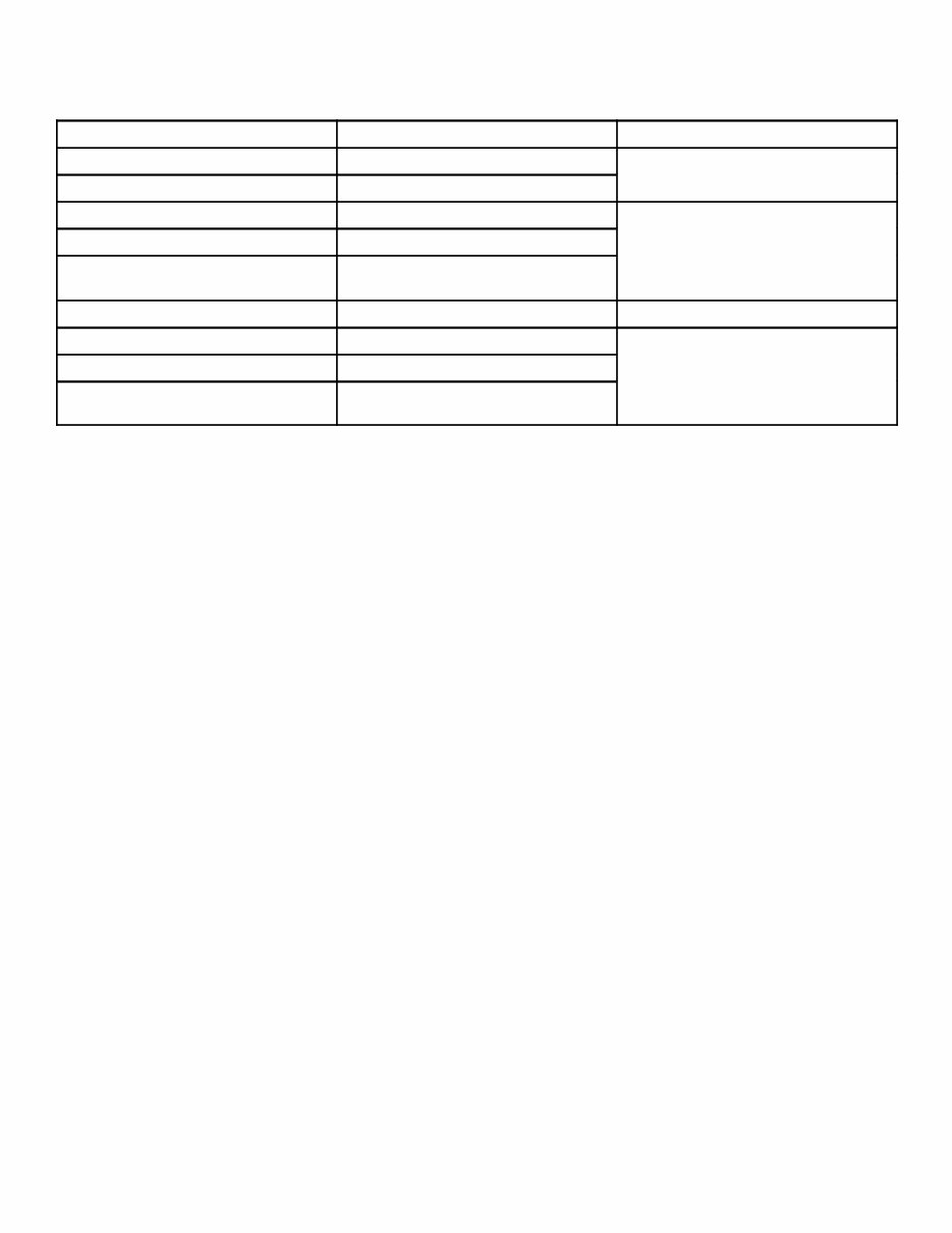
90-823226--1 996 iii V-6 Models Covered in This Manual Model Serial Number Model Year MCM 4.3L Alpha OF000615 - OF800000 1993 - 1996 MCM 4.3LX Alpha OF001220 - OF800000 1993 - 1996 MCM 4.3LX Gen+ Alpha OF803000 and Above d Ab MCM 4.3LXH Gen+ Alpha OF803114 and Above 1996 and Above MCM 262 Magnum EFI Gen + Alpha OF803800 and Above 1996 and Above MCM 4.3LX Bravo OF 605305 - OF800000 1996 MCM 4.3LX Gen+ Bravo OF831000 and Above d Ab MCM 4.3LXH Gen+ Bravo OF803400 and Above 1996 and Above MCM 262 Magnum EFI Gen+ Bravo OF803802 and Above 1996 and Above
90-823226--1 996 iv Service Manual Outline SECTION 1 - Important Information A - General Information B - Maintenance C - Troubleshooting SECTION 2 - Removal and Installation A - MCM Models - Alpha Drives A - MCM Models - Bravo Drives SECTION 3 - Engine A - 262 CID / 4.3L SECTION 4 - Electrical Systems A - Starting System B - Ignition System C - Charging System D - Instrumentation E - Wiring Diagrams SECTION 5 - Fuel System A - Fuel Delivery System B - MerCarb 2 Barrel Carburetor C - Weber 4 Barrel Carburetor D - Electronic Fuel Injection (Throttle Body) A - BSO / SAV Emission SECTION 6 - Cooling System A - Seawater Cooled Models B - Closed Cooled Models SECTION 7 - Exhaust System A - General B - Manifold and Elbows C - Risers D - Collectors SECTION 8 - Power Steering A - Pump
A 1 72000 IMPORTANT INFORMATION GENERAL INFORMATION
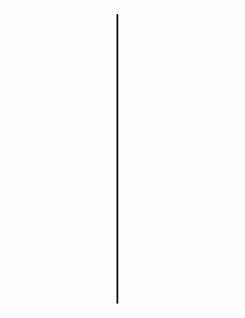
GENERAL INFORMATION - 1A-1 90-823226--1 996 Introduction This comprehensive overhaul and repair manual is designed as a service guide for the models previous- ly listed. It provides specific information, including procedures for disassembly, inspection, assembly and adjustment to enable dealers and service me- chanics to repair and tune these engines. Before attempting repairs or tune-up, it is suggested that the procedure first be read through to gain knowl- edge of the methods and tools used and the cautions and warnings required for safety. How to Use This Manual This manual is divided into sections which represent major components and systems. Some sections are further divided into parts which more fully describe the component. Sections and section parts are listed on the “Service Manual Outline” page following “V-8 Models Covered in This Manual” page. Page Numbering Two number groups appear at the bottom of each page. Following is an example and descrip- tion. 72426
1A-2 - GENERAL INFORMATION 90-8253226--1 996 How To Read Parts Manual 841-824146 1 CYLINDER BLOCK (See Note) 1 19-34270 2 EXPANSION PLUG 8 17-35465 3 DOWEL PIN 4 22-72640 4 EXPANSION PLUG 2 23-85674 5 BEARING UNIT (SET) 1 22-48556 6 BUSHING 2 22-32802 7 PIPE PLUG 1 22-42796 8 BY-PASS VALVE 1 19-816565 9 PLUG 1 811844 10 LIFTER 12 824331 11 RETAINER 2 10-824332 12 SCREW 4 824148 13 BALANCED SHAFT 1 31-824150 14 BEARING (REAR) 1 NOTE: 841-824146 Cylinder Block includes only standard pistons, piston rings, crankshaft bearings and camshaft bearings. PART NO. REF. NO. DESCRIPTION QUAN. a A. Part Number: For part ordering - Note N.S.S. for Reference Numbers, (not shown above) - means Not Sold Separately by Mercury Marine, however, in some cases, the G.M. Part Number (for the item) is given in the Description Column. B. Reference Number: For part Shown on exploded parts view. C. Description: This is the most important column because it gives: 1) Description of Part: Ref. No. 1 is a Cylinder Block Assembly, No. 13 is the Balanced Shaft, etc. 2) What parts are included with a certain part: Notice how the Description of Part, for Ref. Nos. 1, and 10 through 13, are at the left side of the column. Description of Part for Ref. Nos. 2 thru 9 are indented under “Cylinder Block”. If Ref. No. 1 (Cylinder Block) was ordered, all indented parts (Ref. Nos. 2 thru 9) would come with the part. Ref. Nos. 10 thru 14 would not come with Ref. No. 1 and would have to be ordered separately. If 2 Cylinder Blocks were listed, both cylinder blocks would come with the indented parts. In some cases, an indented part will have another part indented under it. The second indented part will come with the first indented part. 3) Serial number break: If serial number information is listed, check product serial number to ensure that correct part is ordered. 4) Special information: Many times special information will be shown after description such as; L.H. Rotation, R. H. Rotation, Filter up, Filter Down, etc. This will help in selecting the correct part. D. Quantity: Quantity that has to be ordered. E. Special Information Block: Additional information, part numbers for gasket sets, etc. b c d e CYLINDER BLOCK AND CAMSHAFT
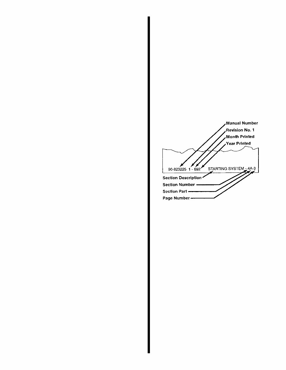
GENERAL INFORMATION - 1A-3 90-823226--1 996 Directional References Front of boat is bow; rear is stern. Starboard side is right side; port side is left side. In this maintenance manual, all directional references are given as they appear when viewing boat from stern looking toward bow. 72000 STARBOARD (RIGHT) PORT (LEFT) FORE or BOW (FRONT) AFT or STERN (REAR) Engine Rotation Engine rotation is determined by observing flywheel rotation from the rear (stern end) of the engine look- ing forward (toward water pump end). Propeller rota- tion is not necessarily the same as engine rotation. When ordering replacement engine, short blocks or parts for engine, be certain to check engine rotation. Do not rely on propeller rotation in determining en- gine rotation. 72001 Standard Left Hand Rotation Engine Serial Number Locations 72975 b a a - Serial Number Plate b - Starter Motor Propeller Information Refer to the “Propeller” section in appropriate Mer- Cruiser Stern Drive Service Manual, or order publica- tion 90-86144, “What You Should Know About Quick- silver Propellers.” Changing diameter, pitch or coupling of a propeller will affect engine RPM and boat performance . The blade configuration also will affect performance. Two like propellers, same pitch and diameter, from two dif- ferent manufacturers also will perform differently. It is the responsibility of the boat manufacturer and/or selling dealer to equip the boat with the correct pro- peller to allow the engine to operate within its speci- fied RPM range at wide-open-throttle (W.O.T.). Because of the many variables of boat design and operation, only testing will determine the best propel- ler for the particular application. To test for correct propeller, operate boat (with an av- erage load onboard) at W.O.T. and check RPM with an accurate tachometer. Engine RPM should be near top of the specified range so that, under heavy load, engine speed will not fall below specifications. If engine exceeds the specified RPM, an increase in pitch and/or diameter is required. If engine is below rated RPM, a decrease in pitch and/or diameter is required. Normally, a change of approximately 300 to 500 RPM will be achieved for each single pitch change of a propeller.
Upon purchasing this manual, you will receive a .PDF file containing an email contact. After contacting us, you will receive a reply with a link to access the manual for your 1997 MERCURY MERCRUISER 4.3L LX LXH GEN+.
This comprehensive manual covers every aspect of your machine, providing detailed guidance for tasks ranging from an oil change to a transmission swap. With hundreds of pages, it includes numerous illustrations and easy-to-follow instructions, making it suitable for both professional mechanics and DIY enthusiasts. The manual also features a search function for easy navigation and the option to print specific pages as needed.
Designed as a Factory Service Repair Manual, it offers step-by-step instructions for maintenance and repair, equipping owners with the knowledge typically possessed by factory-trained technicians. By utilizing the insights provided in this manual, any owner can confidently make informed decisions regarding the upkeep and repair of their machine.
Rest assured, in addition to the high-quality service manual, we are committed to delivering excellent customer service, ensuring your satisfaction with your purchase.
Recently Viewed
5,521,897Happy Clients
2,594,462eManuals
1,120,453Trusted Sellers
15Years in Business
Price:
Actual Price:
1997 MERCURY MERCRUISER 4.3L LX LXH GEN+ Factory Service & Work Shop Manual