90-861329--1 MARCH 1999 Page i Notice Throughout this publication, “Dangers”, “Warnings” and “Cautions” (accompanied by the In- ternational HAZARD Symbol ) are used to alert the mechanic to special instructions con- cerning a particular service or operation that may be hazardous if performed incorrectly or carelessly. OBSERVE THEM CAREFULLY! These “Safety Alerts” alone cannot eliminate the hazards that they signal. Strict compliance to these special instructions when performing the service, plus “Common Sense” operation, are major accident prevention measures. DANGER DANGER - Immediate hazards which WILL result in severe personal injury or death. WARNING WARNING - Hazards or unsafe practices which COULD result in severe personal in- jury or death. CAUTION Hazards or unsafe practices which could result in minor personal injury or product or property damage. Notice to Users of This Manual This service manual has been written and published by the Service Department of Mercury Marine to aid our dealers’ mechanics and company service personnel when servicing the products described herein. It is assumed that these personnel are familiar with the servicing procedures of these prod- ucts, or like or similar products manufactured and marketed by Mercury Marine, that they have been trained in the recommended servicing procedures of these products which in- cludes the use of mechanics’ common hand tools and the special Mercury Marine or recom- mended tools from other suppliers. We could not possibly know of and advise the service trade of all conceivable procedures by which a service might be performed and of the possible hazards and/or results of each method. We have not undertaken any such wide evaluation. Therefore, anyone who uses a service procedure and/or tool, which is not recommended by the manufacturer, first must completely satisfy himself that neither his nor the products safety will be endangered by the service procedure selected. All information, illustrations and specifications contained in this manual are based on the latest product information available at the time of publication. As required, revisions to this manual will be sent to all dealers contracted by us to sell and/or service these products. It should be kept in mind, while working on the product, that the electrical system and ignition system are capable of violent and damaging short circuits or severe electrical shocks. When performing any work where electrical terminals could possibly be grounded or touched by the mechanic, the battery cables should be disconnected at the battery. Any time the intake or exhaust openings are exposed during service they should be covered to protect against accidental entrance of foreign material which could enter the cylinders and cause extensive internal damage when the engine is started.
Page ii 90-861329--1 MARCH 1999 It is important to note, during any maintenance procedure replacement fasteners must have the same measurements and strength as those removed. Numbers on the heads of the met- ric bolts and on the surfaces of metric nuts indicate their strength. American bolts use radial lines for this purpose, while most American nuts do not have strength markings. Mis- matched or incorrect fasteners can result in damage or malfunction, or possibly personal injury. Therefore, fasteners removed should be saved for reuse in the same locations when- ever possible. Where the fasteners are not satisfactory for re-use, care should be taken to select a replacement that matches the original. We reserve the right to make changes to this manual without prior notification. Refer to dealer service bulletins for other pertinent information concerning the products de- scribed in this manual. Engine Mechanical Components Many of the engine mechanical components are designed for marine applications. Unlike automotive engines, marine engines are subjected to extended periods of heavy load and wide-open-throttle operation and, therefore, require heavy-duty components. Special marine engine parts have design and manufacturing specifications which are required to provide long life and dependable performance. Marine engine parts also must be able to resist the corrosive action of salt or brackish water that will rust or corrode standard automo- tive parts within a short period of time. Failure to use recommended Quicksilver service replacement parts can result in poor en- gine performance and/or durability, rapid corrosion of parts subjected to salt water and possibly complete failure of the engine. Use of parts other than recommended service replacement parts, will void the warranty on those parts which are damaged as a result of the use of other than recommended replace- ment parts. Replacement Parts WARNING Electrical, ignition and fuel system components on MerCruiser Engines and Stern Drives are designed and manufactured to comply with U.S. Coast Guard Rules and Regulations to minimize risks of fire or explosion. Use of replacement electrical, ignition or fuel system components, which do not comply to these rules and regulations, could result in a fire or explosion hazard and should be avoided. When servicing the electrical, ignition and fuel systems, it is extremely important that all components are properly installed and tightened. If not, any electrical or ig- nition component opening would permit sparks to ignite fuel vapors from fuel sys- tem leaks, if they existed. Models Covered in This Manual Model Serial Number Model Year MCM 3.0L Alpha OL010042 and Above 1998 -
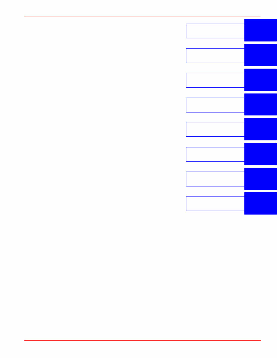
1 2 3 4 5 6 7 8 Important Information Removal And Installation Engine Electrical System Fuel System Cooling System Exhaust System Power Steering 90-861329--1 MARCH 1999 Page iii Service Manual Outline Section 1 - Important Information A - General Information B - Maintenance C - Troubleshooting Section 2 - Removal and Installation A - MCM 3.0L (181 CID) - Alpha Drive Section 3 - Engine A - 3.0L (181 CID) Section 4 - Electrical System A - Starting System B - Ignition System C - Charging System D - Instrumentation E - Wiring Diagrams Section 5 - Fuel System A - Fuel Pump B - MerCarb 2-Barrel Section 6 - Cooling System A - Seawater Cooled Models B - Closed Cooled Models Section 7 - Exhaust System A - Exhaust Manifolds / Elbows Section 8 - Power Steering A - Power Steering
Page iv 90-861329--1 MARCH 1999 THIS PAGE IS INTENTIONALLY BLANK
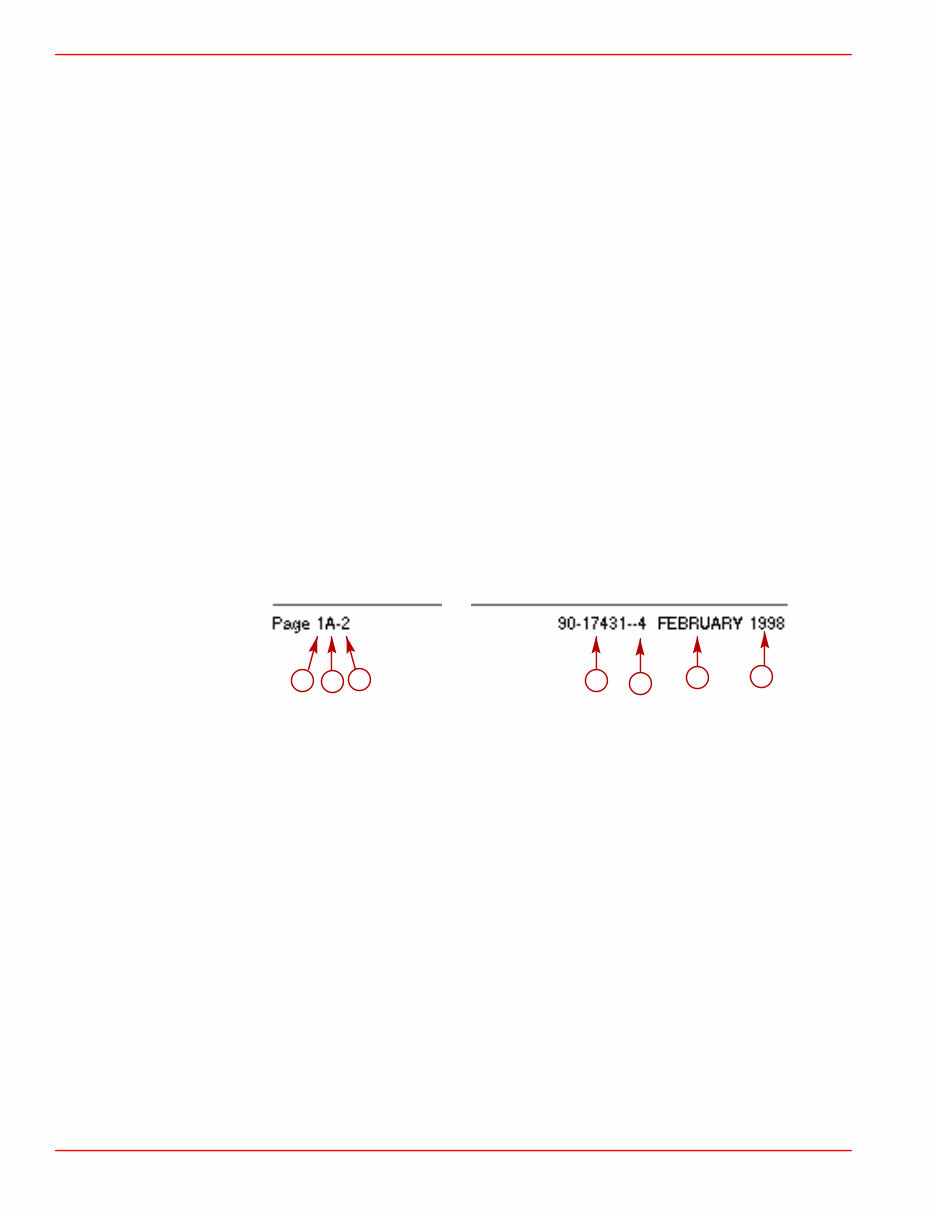
GENERAL INFORMATION SERVICE MANUAL NUMBER 26 Page 1A-2 90-861329--1 MARCH 1999 Introduction This comprehensive overhaul and repair manual is designed as a service guide for the mod- els previously listed. It provides specific information, including procedures for disassembly, inspection, assembly and adjustment to enable dealers and service mechanics to repair and tune these engines. Before attempting repairs or tune-up, it is suggested that the procedure first be read through to gain knowledge of the methods and tools used and the cautions and warnings required for safety. How to Use This Manual This manual is divided into sections which represent major components and systems. Some sections are further divided into parts which more fully describe the component. Sections and section parts are listed on the “Service Manual Outline” page following “V-8 Models Covered in This Manual” page. Page Numbering Two number groups appear at the bottom of each page. Following is an example and description. a b c d e f g a- Section Number b- Section Part c- Page Number d- Manual Part Number e- Revision Number f- Month Printed g- Year Printed
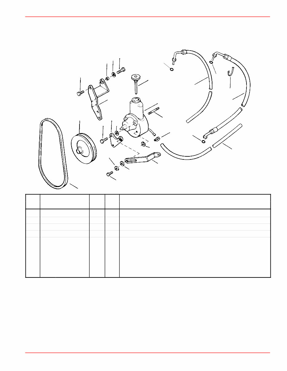
GENERAL INFORMATION SERVICE MANUAL NUMBER 26 90-861329--1 MARCH 1999 Page 1A-3 How to Read a Parts Manual POWER STEERING PUMP ASSEMBLY 1 2 3 4 5 6 7 8 9 10 REF. NO. PART NO. SYM. QTY. DESCRIPTION 1 90507A12 1 PUMP ASSEMBLY–Power Steering 2 36- 95805 1 CAP 3 73873A1 1 PULLEY 4 16- 41877 1 STUD 5 57- 65607T 1 V-BELT 6 32- 806684 1 HOSE–Pressure (FITTINGS ON BOTH ENDS) 7 25- 89879 1 O-RING 8 25- 806232 1 O-RING 9 13- 35048 1 LOCKWASHER (3/8 in.) 10 61990 1 CABLE TIE REF. NO. : Number shown next to part on exploded view PART NO. : Mercury Part Number for ordering. If NSS (not sold separately) sometimes GM part number will be given in description column. QTY. : The quantity that must be ordered. DESCRIPTION : Description of part, what parts are included with a part (all indented items come with the main item above the indented parts), serial number information, and special information.
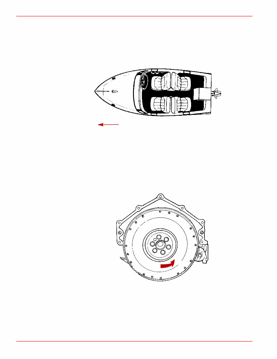
GENERAL INFORMATION SERVICE MANUAL NUMBER 26 Page 1A-4 90-861329--1 MARCH 1999 Directional References Front of boat is bow; rear is stern. Starboard side is right side; port side is left side. In this maintenance manual, all directional references are given as they appear when viewing boat from stern looking toward bow. 72000 STARBOARD (RIGHT) PORT (LEFT) FORE or BOW (FRONT) AFT or STERN (REAR) Engine Rotation Engine rotation is determined by observing flywheel rotation from the rear (stern end) of the engine looking forward (toward water pump end). Propeller rotation is not necessarily the same as engine rotation. When ordering replacement engine, short blocks or parts for engine, be certain to check engine rotation. Do not rely on propeller rotation in determining engine rotation. 72001 Standard Left Hand Rotation
This service manual is for the 1998-2003 Mercury Mercruiser 3.0L (181 CID) GM 4-Cylinder Marine Engines, covering specific engine models including those identified as the MCM 3.0L Alpha with Serial Number OL010042 and above. It is designed to provide comprehensive guidance for both professional technicians and do-it-yourself mechanics. The manual includes essential information on maintenance, troubleshooting, removal and installation, engine specifics, electrical system, fuel system, cooling system, exhaust system, power steering, and more.
It contains detailed step-by-step procedures, illustrations, diagrams, and specifications to facilitate part removal, disassembly, cleaning, assembly, and installation. Additionally, an advanced troubleshooting guide is provided to diagnose and correct any issues. The manual also addresses common questions related to accessing and using the content, making it user-friendly and accessible to those with basic electrical and mechanical knowledge.
Upon download, the manual can be stored on a computer indefinitely for future reference without the need for any special viewing software. It is specific to the 1998-2003 Mercury Mercruiser 3.0L (181 CID) GM 4-Cylinder Marine Engines, ensuring precise and accurate information. The manual is available in a downloadable format, ensuring instant access for all users.
Section 1 - Important Information
A - General Information
B - Maintenance
C - Troubleshooting
Section 2 - Removal and Installation
A - MCM 3.0L (181 CID) - Alpha Drive
Section 3 - Engine
A - 3.0L (181 CID)
Section 4 - Electrical System
A - Starting System
B - Ignition System
C - Charging System
D - Instrumentation
E - Wiring Diagrams
Section 5 - Fuel System
A - Fuel Pump
B - MerCarb 2-Barrel
Section 6 - Cooling System
A - Seawater Cooled Models
B - Closed Cooled Models
Section 7 - Exhaust System
A - Exhaust Manifolds / Elbows
Section 8 - Power Steering
A - Power Steering
For instant access to this manual, simply complete the payment process and a download link will be sent to your computer within seconds. This manual is an invaluable resource for maintaining and repairing the 1998-2003 Mercury Mercruiser 3.0L (181 CID) GM 4-Cylinder Marine Engines, providing the necessary knowledge and guidance for safe and effective repairs.

 Repair Manual")