

gray marine vintage chris craft engine manuals 4 & 6 cyl
What's Included?
Fast Download Speeds
Online & Offline Access
Access PDF Contents & Bookmarks
Full Search Facility
Print one or all pages of your manual
I
Maintenance
Manual
Form No. 865

MAINTENANCE
MANUAL
GRAYMARINE
GASOLINE ENGINES
FOUR AND SIX
CYLINDER MODELS
Specifications for Current
9 and
Non-Current Models
Pages S-2 through S-15
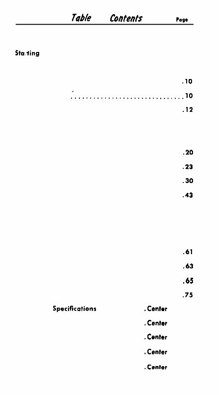
Tab/e o f Conteots Page 1
Maintenance Instructions ........................ 3
Sta,iing Engine First Time ........................ 6
Operating Instructions. ......................... 8
Adjustments on New Engine .................... .lO
Fuel and Fueling ................................ 10
Engine Installation ............................. .12
Water Piping Diagram .......................... 14
Fuel System ................................... 1 6
lubricating System.
...........................
.20
Cooling System. .............................. .23
Electrical System. ............................. .30
Transmission.
................................
.43
Cylinder Head ................................. 5 5
Valves ........................................ 5 7
Timing ........................................ 6 0
Laying-Up Instructions .........................
.61
Starting’ Engine After Storage ...................
.63
Trouble-Shooting Guide ........................
.65
Propeller Sizes, Average. ......................
.75
Condensed Specifications ............. .Center Section
Condensed Adjustment Data .......... .Center Section
Wiring Diagrams .................... .Center Section
Engine Installation Data .............. .Center Section
Gray Service Warranty ............... .Center Section
INTRODUCTION
This pocket-sired hand book is supplied as a service to
Gray owners. It is one evidence of our determination to
make Gray service the most complete and useful in the
industry. It covers both current models and older models.
The scope of this manual is necessarily limited by its
size but includes gasoline marine engine operating in-
structions, trouble shooting guide and directions for mak-
ing simple adjustments to engine and accessories: such
operations as can be done on the engine in the boat.
Note that the section on “Installation” covers only such
details as affect the care of the engine.
The intent of the booklet is one of usefulness, and not to
encourage tinkering. In the interest of good service,
safety and long engine life the manufacturer recommends
that major repairs can always best be done by experipnced
marine service stations with a reputation for competent
workmanship and a proper acceptance of the responsibility.
Gray Marine Engine Division will be glad to recommend
the nearest competent marine shop if your boat 1s not
located near an authorized dealer. Also, remember that
carburetors and electric accessories are made by com-
panies with widespread service facilities; consult the classi-
fied telephone directory.
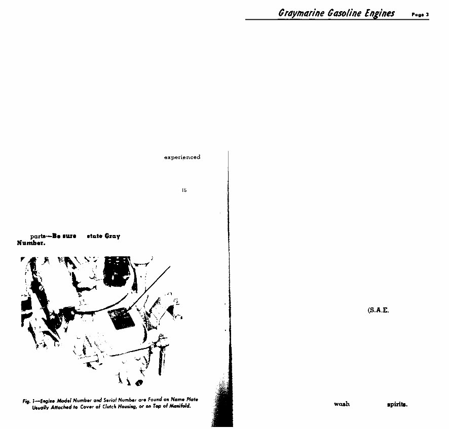
Important-When requesting information or when order-
ing parts--b. sure to state Gxay Engine Model and Serial
Nllmber.
MAINTENANCE
INSTRUCTIONS
DAILY
l Ventilate engine compartment thoroughly
before starting engine.
l Check pump flow by observing water and
steam at exhaust outlet, each time engine
is started. Do this at once.
. Check lubricating oil level in crankcase
(engine not running), and when necessary
refill to high level mark on depth stick, using
S.A.E. 30 oil.
l At the same time, check oil level in hydraulic
reverse gear. (This applies only to engines so
equipped, when reverse gear has a separate
oil supply.) Note: if oil needs to be added,
look for a leak, because reverse gear normally
consumes no oil.
l Give grease cups on water pump one-half
turn. Use water-proof grease. Do not over
grease.
EVERY 50 HOURS
OF OPERATION
l Inspect sea water strainer.
l Check water level in battery. Proper fluid
gravity is 1.275.
l Put 3 to 5 drops of engine oil (S.A.E. 30)
in the oiler on the outside of distributor
body; or give grease cup one-half turn.
depending on model.
l Remove oil from crankcase, using Gray sump
pump, and refill with fresh oil, S.A.E. 30, to
high mark on oil depth gauge. Note: Before
removing old oil. run the engine until it is
thoroughly warm.
l Put 3 or 4 drops of engine oil (SAX. 30) in
oiler on generator, and two drops in oiler on
cranking motor. (Some models have sealed
bearings, so will have no oilers.)
ONCE A MONTH
l Inspect and clean Thermogard element. See
page 27
l Clean sediment bowl on fuel pump.
l Check adjustment of clutch and reverse gear.
See pages 43 to 52 for directions.
l Inspect flame arrester to make sure the air
passages are clean and free from oil or lint.
If dirty, remove and wash in mineral spiriti.
?ope 4 Graytnahe Gasolrire Engines
EVERY 150 HOURS
0 Replace cartridge in lubricating oil filter, if
engine is so equipped.
l Apply one drop only of light engine oil
(S.A.E. 10) to the breaker arm hinge pin in
distributor.
l Givegrease cup on tachometer drive one turn.
(Applies only to right angle type mounted on
cylinder head.)
l Remove the distributor rotor and apply 3 to
5 drops of light engine oil (S.A.E. 10) to the
felt in the top of the breaker cam and to the
governor weight pivots.
TWICE A SEASON
“TUNE UP”
l Clean the engine thoroughly.
. Check distributor setting. See page 39.
l Check carburetor adjustment. See page 18.
l Check engine coupling for misalignment.
Tighten lag bolts holding engine to bed.
l Check valve tappet adjustment. For correct
clearance, see pages S-3, S-4, S-13 and S-15.
in center section.
l Chock grease in drive gear housing of double
gear type water pumps. Add bearing grease
(EQ-2095) if required.
0 Remove the distributor head and smear a bit
of grease the size of a match head on the
lobes of the breaker cam.
0 Clean and adjust breaker points on distrib-
utor. Points should contact evenly, and gap
must not exceed .020” or condenser can be
burned out. See page 37.
l Check spark plugs and set gap, using a round
wire feeler gauge. Clean fouled plugs and
ooarch for cause of fouling. Replace crocked
or doubtful plugs. Use plugs of correct heat
range.
KEEP A SERVICE LOG
Maintenance lnstmctions
l Inspect all wiring for loose connections or
worn insulation. Clean battery terminals
with soda solution and coat lightly with
Vaseline or grease after connection is made.
EVERY 1000 HOURS
OR ONCE A SEASON
l Change oil in hydraulic reverse gear if engine
is so equipped. Use Automatic Transmission
Oil Type “A”, Suffix “A”, (SAE 30 engine oil
may be used only in an emergency.) IM-
PORTANT: after running engine briefly in
both forward and reverse, stop engine and
recheck transmission oil level. See page 52.
l Grind and adjust valves.
l Check valve stems for carbon.
a Give engine a thorough going-over.
0 Clean Oil Cooler.
l Clean commutator on generator, using No. 00
sandpaper. Do not use emery cloth.
l Ii compression is weak, look for imperfectly
seating valves or rings stuck in groove* on
piston.
EVERY 2500 HOURS
l Time for a major overhaul.
l Install new piston rings. Check piston clear-
ance.
l Check bearings. When oil presmure drops be-
low 20 pounds, this ia an indication of worn
bearings.
Graymarhe Gasohe bghes
INSTRUCTIONS ON STARTING ENGINE
FIRST TIME
BEFORE STARTING THE ENGINE
After the engine has been properly installed ond all con-
trols properly connected. the following instructions are to
be carried out before starting a new engine:
1. Check Fuel Supply: Be sure the tank is clean, then fill
with a good grade of gasoline. Refer to page S-2 in
center section for fuel recommendation. Some models
require premium ethyl.
2. Check Lubricating Oil in Crankcase: Engine is shipped
dry from factory with oil drained from the crankcane.
Do not fail to check oil level. Fill to the high level notch
on oil depth gauge, using a good grade of oil, S.A.E.
viscosity No. 30. Lift oil depth gauge during filling to
permit escape of air. Note: If engine is equipped with
hydraulic reverse gear, check oil depth stick on trans-
mission for separate oil supply, using Automatic
Transmission Oil, Type “A”, Suffix “A”.
3. Check Lag Bolts holding engine to bed: must be tight.
IMPORTANT: If the boat came off a train or truck, or if
it has been out of the water for considerable time, check
the shaft alignment. (Instructions on page 16.)
4. Inspect the Engine for loose nuts or screws. Transpor-
tation frequently loosens fastenings on a new engine,
on account of gasket shrinkage. After engine has had a
preliminary run, take up on cylinder head nuts. See p. 56
5. Check Storage Battery: Make sure that storage battery
is filled, with water level at least 3,s” above the plates,
and fully charged. Proper fluid gravity is 1.275. Low
battery will result in slow cranking speed and weak
spark.
6. Check All Electrical Connections including battery
cables. Make sure they are tight, and all connections
soldered. (Use rosin flux in soldering.)
7. Check Water Circulation System: Open the gate valve
on the cooling water intake line. This valve should be
located in the bottom of the boat. Caution: if water
pump is rubber impeller type, it must be primed at first
start of the season.
6. Check All Controls to make sure they are working
freely with sufficient travel so that they do not strike
against woodwork. This refers to choke, throttle and
rover*8 controls.
ODefatiirp lnZrruction.5
9. Safety Precautions: Check engine compartment and
bilge for gasoline fumes. If boat is equipped with
ventilating fan, run it for 5 minutes before starting;
otherwise open hatch or engine box and let dead air out.
10. Turn on the Gasoline: The shut-off cock is properly
located near the fuel tank.
11
12.
1.
2.
3.
4.
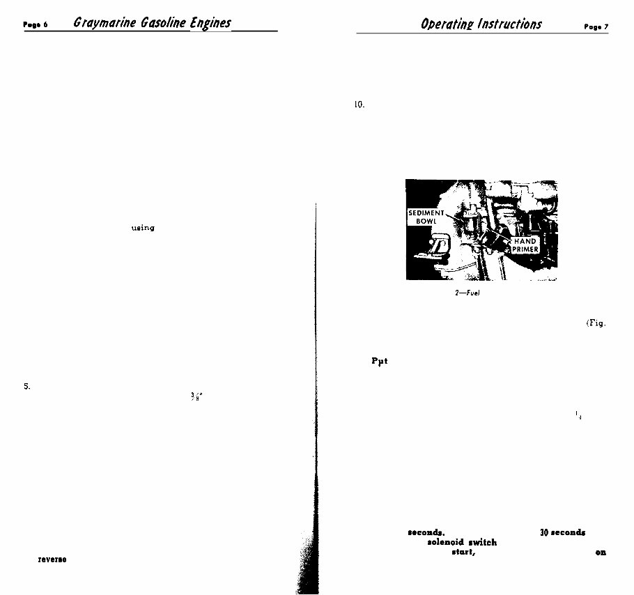
Fig. l--Fuel Pump Primer
Fill Carburetor: Use hand primer on fuel pump (Fig.
2 to fill sediment bowl and carburetor. (Note: on some
small engines fuel pump does not have hand primer.
Ppt Clutch in Neutral.
HOW TO START THE ENGINE
Set the Throttle above idling position, about I4 open.
Pull Out the Choke: Keep your hand on it for quick
adjustment as soon as the engine starts. A marine
engine, particularly if it has two carburetors. needs
plenty of choke to start.
Turn on Ignition Switch.
Press Starter Button.
CAUTION: Do not operate cranking motor longer
than 30 8eCOAdI. A longer period than 30 recondr may
damage the rolenoid awitch and cranking motor. If
l agiae does not 8tart, refer to detailed instructions OA
Page 65.
hp. 8 Graymarine Gasoline Engines
NOTE: Engines which have been in transit and storage
for a period of weeks may start hard the first time. In
such case, remove spark plugs and clean the electrodes.
While the plugs are out, put a tablespoonful (no more)
of light oil, SAE 10. in each cylinder to provide an
initial oil seal between piston rings and cylinder walls.
Memo on Flooding: If you flood the engine by too
much choking, the correct way to dry it out is to open
the throttle wide. Put the choke in the running or
non-choking position. Then with ignition on, crank
the engine a half dozen times. This draws nothing but
air through the carburetor, as the idling jet is out of
action at full throttle, and the engine does not revolve
fast enough for the main jet to go into action.
OPERATING INSTRUCTIONS
1. To Drive the Boat Forward push operating lever
forward until it snaps into a locked position.
2. To Reverre, pull lever back as far as it will go. Reduce
speed before shifting.
CAUTION: The engine must not be operated unless the
cooling water is circulating. See instructions below.
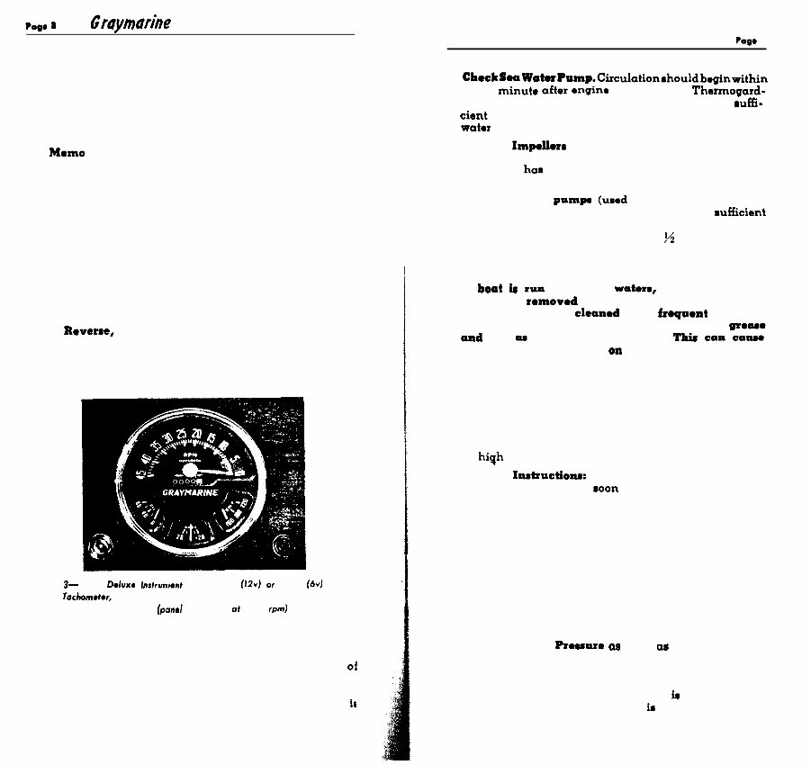
Fig. 3- Gray D&nca Inrlrunren~ Panel 77800 (12~) or 75650 (6~) with
Tachometer, Operating Hours Register, Oil Temperature Gauge,
and Ammeter fpanel calibrated of 1796 rpm)
AFTER THE ENGINE STARTS
Check Oil Pressure Gauge: Normal oil pressure at
operating speeds is 30-40 pounds. An oil pressure 01
less than 20 pounds calls for investigation (5 to 15
pounds is satisfactory at idle). NOTE: Gauge may
show no pressure for a minute or two while the filter ir
filling with oil.
Operating Instructions Pago 9
2. CheckSoaWoterPnmp.Circulationshouldbeginwithin
a half minute aftor engino is started. On Thermogard-
equipped models. only a small amount of water muffi-
cient to cool the tailpipe will be expelled, the rest of the
water being recirculated until engine warms up.
Neoprene Impellorr are lubricated by the flow of water.
Consequently, never operate a dry pump. Always prime
pump if it haa become dry after draining or extended
idleness.
On bronze gear pumpa (used on smaller four-cylin-
der engines) the prime of pump is assisted by sufficient
grease sealing the impellers. If pump does not operate
immediately, turn grease cup down yz turn.
NOTE: Pictures of these units shown on Pages 24, 25.
CAUTION : (Applies only to bronze gear pump) :
If boat t run in muddy woterm, the water pump
should be rcmovcd and all old grease in impeller
housing thoroughly cleaned out at froquont intervals.
Silt which entered the pump will mix with the geam
and act aa a grinding compound. Thir can caume
exceptionally rapid wear on metal parts.
3. The first time the engine is started, run it at idle for 5
minutes, no longer, then stop engine and recheck oil
level in crankcase, and in reverse gear housing when
applicable. (Do not check oil level while engine is
running.) Oil level may be found low due to the fact
that considerable oil is required to fill the oil passages:
or it may be found high if depth gauge was not removed
for venting air during the initial filling. Bring oil level
to high mark on depth gauge.
4. Warm-up Iastructfoas: (To be followed every time you
start a cold engine.) As soon as possible put the clutch
lever in forward position and run at fast idle for 10 to 15
minutes. in order to bring the oil up to proper tempera-
ture for full throttle work. An indication of warm oil
is that the oil pressure will drop off about 5 pounds
from what it was when engine was cold.
IMPORTANT: Do not under any circumstances race
the engine with clutch disengaged.
FULL THROTTLE OPERATION
1. Recheck the Oil Preuwe a soon W you try out the
boat at full speed. If indicating needle on the oil
pressure gauge fluctuates wildly, this will indicate
either a leak in the oil line, or that the angle of the
engine is such that oil pick-up screen ia not completely
submerged. The remedy for this in to stop engine and
add more oil. See Fig. 10, page 21. for an understanding
of the relationship between pick-up screen and oil level.
?ega 10 Graymarine Gasoline Enghes
2. RadPce Engine Speed When Reversing: Gear should
not be reversed at full engine speed except in extreme
emergency.
3. Although all Graymarine engines ara thoroughly
tested at the factory, good judgment is expected on
the warm-up and operation during the early life of
the engine. It takes from fifteen to twenty hours run-
in to break in an engine for peak performance. On
high speed models, oil consumption will be more until
the piston rings fit themselves perfectly inside cylinder
walls, after a few hours of fast operation.
ADJUSTMENTS ON A NEW ENGINE
1. Propeller Shaft Alignment: If the boat is new. be sure
to check the alignment within a few days, after the
hull has soaked up some water, because the hull is
liable to change its shape slightly, especially when
loaded, resulting in binding on the shaft.
2. Carburetors: Careful adjustment is made in the test
room. Never re-adjust carburetor unless engine is
warm and under full load. Make sure that control ex-
tensions permit full travel of throttle and choke levers.
3. Clutch Adjustment: After the first few hours of opera-
tion examine the adjustment of manual gear. Clutch
lever should stay in either position without being held.
It should snap into the forward position and shouldstay
in reverse without forcing. (NOTE : This does not apply
to some four-cylinder models which have wedge mech-
anism for reverse position, and must be held in reverse.)
For instructions on clutch adjustment, see pages 45 to 52.
Wanting: Never operate engine with loose and slipping
clutch, because this condition will generate heat by
friction, warping and galling the clutch plates, causing
permanent damage. Clutch trouble is nearly always
due to negligence.
4. After first 10 hours of operation, have the valve tappets
readjusted to specified clearance (see center section) by a
competent marine service station. This is your responsibihty.
5. Valve Sticking: Sometime5 valve5 on new engine5 or
those which have been in storage tend to stick. See
page 59 for remedy.
FUEL
The Gray Marine Motor Company approve5 the use of high
grade gasolines as marketed by reputable refiners. Good,
fresh gasoline of the correct octane for the particular model
engine should be used; the correct grade for each model
Opefating hstfucth Pm00 11
is shown in the data section for current models (page
S-2) on tinted paper at center of book. Good gasolines are
processed against gum forming tendencies even whon
subjected to long time storage. Some gasolines form gum
deposits rather quickly; these deposits appear as a jelly-
like coating within the copper fuel tanks; they are also
observed as a whitish precipitate in the fuel lines, also in
carburetor float bowls and jets, which deposits impair or
restrict fuel flow. This gum-forming tendency with at-
tendant deposit can also contribute to impaired operation
of engtne intake valves. Where the boat is to be out of
commission for 30 days or more. drain the fuel tanks, fuel
linem, fuel pump and the carburetor as a precaution
against possible gum forming deposits within these parts.
Use good gasolino muppliod by a reputable fuel marketer, a
gasolino of the required octane value am prescribed for your
Graymarine engine.
On brand new steel tanks, the first fill of gasoline will often
carry off rust-inhibitor coatings, flux and other matter
which will bo detrimental to the carburetor. Thorofore, we
suggest the addition of a solvent such as Siloo, Casito, or
equivalent, in new tanks.
MOTORBOAT FUELING INSTRUCTIONS
(Issued by the United Staterr Court Guard)
1. Fuel tanks should be properly installed and vonted.
2. Fueling should be completed before dark except in
l mergenciu.
3. Whenover boat is moored at service l tation for fueling:
(a) Do not mmoke. strike matches, or throw switchem.
(b) Stop all engines, motors, fans, and dovices liable
to produce mparkm.
(c) Put out all lights and galley fires.
4. Before mtarting to fuel:
(a) See that boat is moored securely.
(b) Close all ports. windows, doors and hatohr.
(c) Aaoertain dofinitoly how much additional fuel the
tanks will hold.
5. During fueling :
(a) Keep nosxlo of hose or can in contact with fill
opening to guard againmt ponible static spark.
(b) See that no fuel spills got into hull or bilges.
6. After fumling is completed :
(a) Close El1 openingm.
(b) Wipe up a11 spilled fuel.
(c) Open all ports, windows, doors and hatches.
(d) Permit boat to ventilate for at least 5 minutes.
(e) See that there is no odor of gasoline in the l ngtne
room or below decks beforo l tartfng machinq or
lighting fire.
(f) Be prepared to cast off moorings as soon a engine
l tartm.
rag* 12 G faymarhe Gasohe Engines
ENGINE INSTALLATION
Proper installation is a condition of the Gray Warranty. This
brief section is included to give emphasis to some essential details,
because a high percentage of service troubles are caused by
faulty installation.
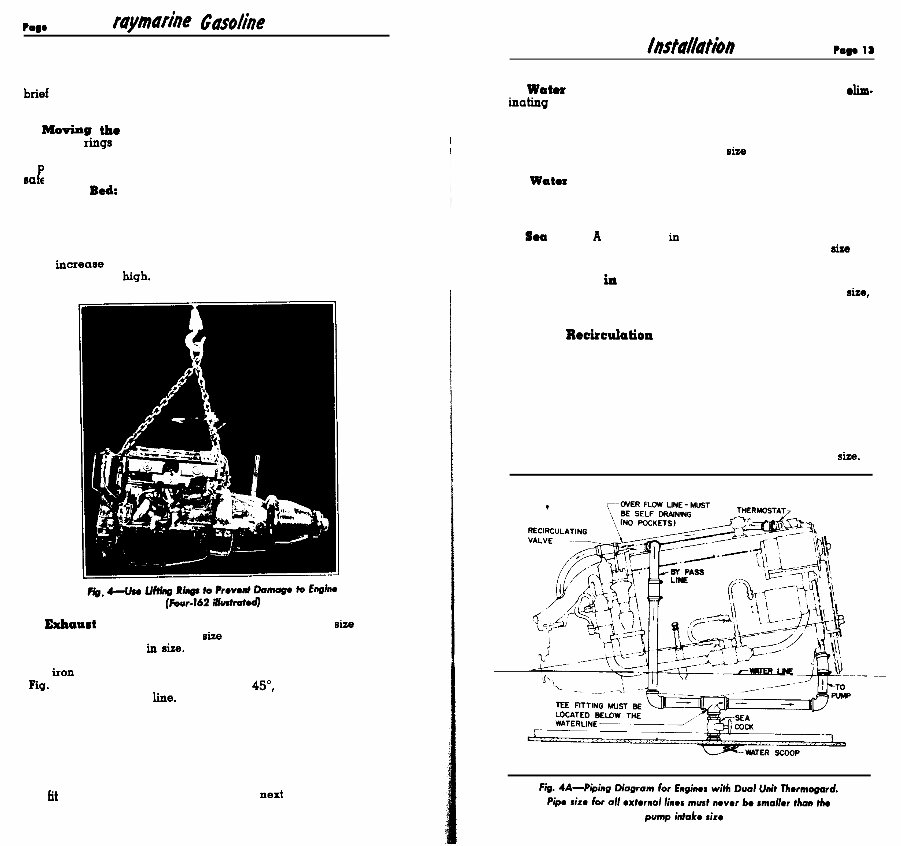
1. Moving tie Engine: The engine is fitted with either one or
two lifting rings designed to carry the full weight of the engine,
therefore auxiliary slings are not required or desired. Never try
to
so ely, and may damage accessories. P
ut a sling around the engine, as this will not hold the engine
2. Engine Bedr This should always be of sufficiently heavy
section to insure rigidity, and well secured to the hull. Maximum
operating angle of the engine at full speed, as mounted on this
bed should not exceed 16 degrees from water level, because at
a higher angle the lubricating oil pick-up screen may not be
fully submerged (see Fig. 10, page 21). Remember that the angle
may increase if the boat is loaded deeply at the stern and the
bow is light and high.
3. Exkaurt Piping: This must never be reduced in sire at any
point smaller than the flange size supplied on exhaust manifold.
It may be increased in sise. Use standard pipe and fittings only,
or tubing of equal or larger inside diameter than the correspond-
ing iron pipe sire. Do not use “street ells” for connections (see
pig. 5). No bends should be more than 45”, and all exhaust exits
must be above water line. For most installations, all of the dis-
charged cooling water can be carried by the tailpipe., Water
MUST enter exhaust pipe at a point lower than exhaust mani-
fold, preferably 6 to 8 inches from flange, so that there will be
no danger of any water getting back through the exhaust valves,
regardless of boat’s pitch. Water stream should enter exhaust
flow diagonally; not at right angle. We recommend the use of a
Graymarine water-cooled elbow at this point, available in sizes
to fit all engine models. (See diagram next page).
4. Watox Piping: Use standard pipe and fittings only, eltm-
inattng all “street ells” which impose a restriction on the flow
(refer to Fig. 5). Connect sections with hose over pipe and hose
clamps for vibration joints. IMPORTANT: Intake piping to water
pump should never be smaller than the I.P.S. of intake fitting on
pump. We recommend using nest pipe size larger than intake of
pump for free flow. Avoid sharp bends.
5. Water Intake Scoop: Through-hull fitting should always be
one size larger than the pump intake sire. Locate the scoop so
that the intake pipe to pump will be as short and straight as
possible. Bends reduce flow and add to load on pump.
6. Soa Cock: A gate valve in water intake pipe is desirable but
not essential. It must be of free tlow type and of sufficient sise to
prevent any restriction to flow.
7. Check Valve in Water Intake Line: When this is an item
of the installation use valve one size larger than intake pipe sise,
reducing to intake pipe size with bushings, to provide adequate
flow area.
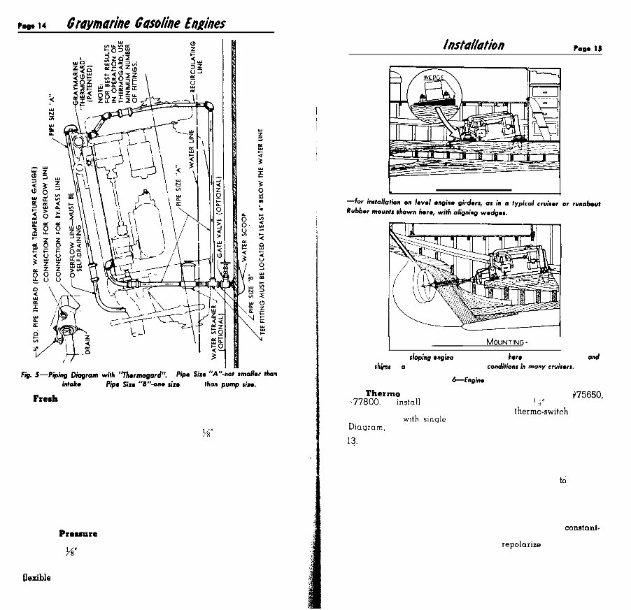
8. Water Recixculation Line: All current models of engines
up to and including those with piston displacement of 226 cu. in.
use a dual unit Thermogard temperature control system with
choke-type thermostat at the outlet to overflow line, and a
pressure valve at the outlet for the recirculation line, piping for
which is shown in Fig. 4h. Larger engines use a single unit
Thermogard valve, shown in Fig. 17, to be piped as shown in
Fig. 5. In both types note that the T-fitting for recirculation line
MUST be located below the load-water-line of boat. It is important
that no restrictions of any kind exist in the recirculation line or the
overflow line. Neither must be smaller than pump intake size.
Pmp. 14 Graymarrie Gasolrire E&/ires
Ffg. 5-Pbfng Diagram with ‘Thermogord”.
Pipe Size “A’‘-not smollw thwa
pump intake size. Pfpo Size ‘W-one sfza larger then pump sire.
9. Fresh Water Cooling System: For engines with this equip-
ment, we insist upon use of a heat exchanger unit approved for
adequate size and proper design. Units supplied by Gray Marine
Motor Company will give perfect service because they are en-
gineered to fit the engine. CAUTION: Remove W” pipe plug vent,
in pump-to-manifold pipe, when filling the system with coolant.
See pages 23-30.
10. Fuel Tubing: Size must not be smaller than the size indi-
cated by the tube nut on fuel pump fitting supplied with engine.
A flexible section of sufficient size is desirable between the fuel
line and fuel pump, or a loop in the tubing may be provided to
prevent breakage due to vibration and strains.
Note: On twin engine installations, if you do not have two gas
tanks, be sure to run a separate line from the tank to each
engine-not through a header line.
11. Oil Prerrure Tube to oil pressure gauge on instrument
panel is connected to a brass fitting on carburetor side of cylinder
block. Use W” tubing, anchored with tape to prevent chafing, and
with a loop in the tubing at engine end to prevent metal fatigue
from normal engine movement. On rubber mounted engines, use
flexible tubing or a flexible section at engine end.
1
A NGLE M OUNTING
I
H ORIZONTAL MOUNTING-
I
-for installation on sloping engino beds, as shown here using solid mounts and
aligning shims in Q typical auxiliary. Similar condffions in many crvisws.
Fig. 6-Fnginm Mounts
12. Therm0 Switch (supplied with Instrument Panels #75650,
z.77800. To mstall this, remove pipe plug from J 5” I.P.S. threaded
hole at front end of cylinder head. Insert thermo-switch element,
and connect with smgle wire to instrument panel. See Wiring
Diagram, page S-6.
13. Tachometer Cable (supplied only with instrument panel).
Connect from instrument panel to fitting on side of reverse gear
housing on most models. Note: on some models this connection
is located in center of cylinder head.
14. Electrical Connections: Follow wiring diagram to conform
to type of generator on engine (pgs. S-6-S-1 1) and use wire sizes
no smaller than those ‘indicated. Solder all connections. Locate
battery as close to engine as possible, with short cable, not
smaller than No. 0. For ground connections, see page S-5.
15. Voltage Regulator (supplied for engines with constant-
voltage generator.) This should conform to ground polarity (see
page S-5). After wiring is completed, repolarize the generator
(instructions are on page S-8). NEVER polarize an alternator.
16. Propeller Size: Final selection of propeller should be size
which will permit the engine to turn close to its maximum rated
rpm. Tables of suggested propeller sizes are on pages 74-75.
You're Reading a Preview
What's Included?
Fast Download Speeds
Online & Offline Access
Access PDF Contents & Bookmarks
Full Search Facility
Print one or all pages of your manual
$35.99
Viewed 42 Times Today


Secure transaction
What's Included?
Fast Download Speeds
Online & Offline Access
Access PDF Contents & Bookmarks
Full Search Facility
Print one or all pages of your manual
$35.99
Get access to comprehensive maintenance and service manuals for Gray Marine vintage Chris Craft engines. These manuals cover 4 and 6 cylinder gasoline engines from 1939 onwards, providing valuable technical information for professional mechanics and DIY enthusiasts alike.


