

BUKH Diesel Engine OWNER USER OPERATOR Manual
What's Included?
Fast Download Speeds
Online & Offline Access
Access PDF Contents & Bookmarks
Full Search Facility
Print one or all pages of your manual
009W0327-R03
OWNER'S HANDBOOK
FOR
BUKH MARINE DIESEL
LIFEBOAT ENGINE
TYPE DV36 ME
BUKH A/S
Aabenraavej 13 - 17
DK - 6340 Krusaa
Tel: +45 74 62 20 88
Fax: +45 74 62 74 07
E-mail: bukh@bukh.dk
www.bukh.dk

OPERATING MANUAL FOR BUKH DV36ME ENGINES
009W0327-R03
- 2 -
CONTENTS
Page
Pictures for recognition of engine ................................................ 3
Introduction .................................................................................. 4
Standard equipment ..................................................................... 4
Operating manual ......................................................................... 4
Preparation for the first start......................................................... 5
Before start ................................................................................... 5
Electric start ................................................................................. 5
Hand start ..................................................................................... 5
After start…………………………………………………….…… ..... 6
Maneuvering ................................................................................ 6
Stopping the engine ..................................................................... 6
Running in .................................................................................... 6
Maintenance ................................................................................. 6
Belt for alternator .......................................................................... 6
Air inlet filter ................................................................................. 6
Fuel filter....................................................................................... 6
Fuel lift pump ................................................................................ 7
Lubricating oil system................................................................... 7
Change of oil ................................................................................ 7
Recommended lubricating oil ...................................................... 7
Change of lubricating oil filter ....................................................... 7
Cooling water system ................................................................... 7
Seawater cooling.......................................................................... 7
Exchange of zinc anode ............................................................... 7
Exchange of impeller.................................................................... 7
Freshwater cooling ....................................................................... 8
Frost precautions ......................................................................... 8
Electrical system .......................................................................... 8
Marine gear .................................................................................. 8
Propeller equipment ..................................................................... 9
Sail drive....................................................................................... 9
Galvanic corrosion ..................................................................... .10
Starting instructions.................................................................... .10
Winter storage of the engine ...................................................... .11
Technical data for engine and gearbox...................................... .12
Recommended maintenance and checklist ............................... .13
Irregular operation ...................................................................... .14
Lubricating oil chart .................................................................... .15
El-diagram .................................................................................. .16
DV36 installation.. ....................................................................... 17
List of representatives ................................................................. 18
General Terms of Sale and Delivery .......................................... .22
OPERATING MANUAL FOR BUKH DV36ME ENGINES
009W0327-R03
- 3 -
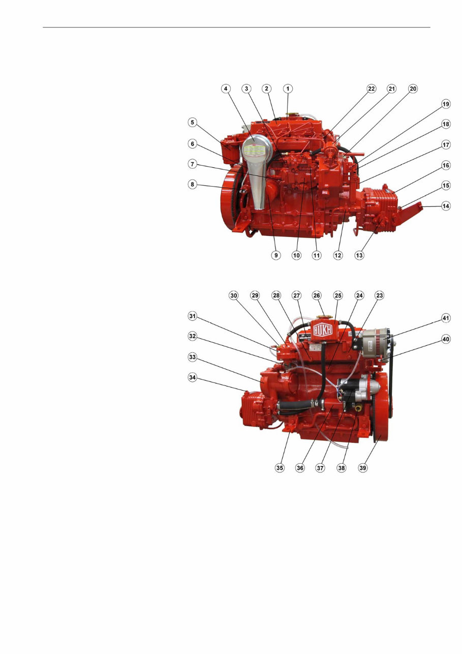
1. Lubricating oil filling plug
2. Valve cover
3. Electric stop solenoid
4. Air filter with noise suppression
5. Fuel filter
6. Cooling water drain plug
7. Dipstick for engine oil
8. Oil pressure switch
9. Lubricating oil filter
10. Fuel pump
11. Control lever
12. Cock
13. Reversing lever for gear
14. Bracket for reversing cable
15. Coupling flange for propeller shaft
16. Reverse-reduction gear
17. Housing for vacuum valve
18. Bilge pump for change of lub. oil
19. Bracket for control cable
20. Electric multi plug
21. Fuel lift pump
22. Lifting fittings
23. Water cooled exhaust manifold
24. Zinc anode
25. Cooling water expansion tank
26. Cooling water filling plug
27. Identification label
28. Water drain plug for exhaust manifold
29. Thermostat housing
30. Cooling water temperature transmitter
31. Exhaust
32. Outlet to keelcooler
33. Circulation pump
34. Dip stick for gear oil
35. Reversible engine mountings
36. Lubricating oil cooler
37. Electric starter
38. Inlet from keel cooler
39. Flywheel
40. Tension device for V-belt
41. Alternator

OPERATING MANUAL FOR BUKH DV36ME ENGINES
009W0327-R03
- 4 -
INTRODUCTION
BASIC ENGINE CONFIGURATION:
The BUKH Marine Diesel engine is a four-stroke marine diesel engine with direct fuel injection and the following basic
equipment:
Crankcase with oil pan, one-piece cylinder head with 2 valves per cylinder, forged crankshaft with counterweights, balance
weights, cast iron connecting rods, light metal pistons, water-cooled exhaust manifold; all necessary pipework for exhaust,
coolant, fuel and lubricating oil are fitted on engine.
A reverse/reduction gearbox with integrated thrust bearing is fitted on the engine.
No BUKH Diesel Engine is sent from the factory without having been thoroughly tested.
The tests have shown that the engine in all aspects is working satisfactorily and is generating its full power.
You will expect the engine to work reliably witout giving any problems, and to achieve this you are asked to follow the
instructions in this manual. By so doing, you will get the best from your BUKH engine.
If a problem with the engine should arise, we ask you to apply to one of our distributors, who will always be ready to
help you, having skilled personnel, necessary tools etc., and at the same time you will be sure that only original BUKH spare
parts are used.
Do always use original BUKH spare parts.
When ordering spare parts from the distributor please state:
Engine type and serial number, description and number of parts.
BUKH A/S
Powering Marine Safety
As BUKH A/S is always endeavouring to improve the engines, the specifications mentioned are subject to alterations
without previous notice.
Read this instruction book thoroughly before starting your new BUKH Diesel Engine.
STANDARD EQUIPMENT for DV36ME
Reverse-reduction gear
Decompression lever
Wet sump lubrication oil system
Full-flow lubrication oil filter
Automatic injection timing
Centrifugal governor
Watercooled exhaust manifold
Air inlet filter and silencer
Fuel lift pump
Electric start
Charging alternator
Operating remote panel with:
a) Charging light
b) Lub. oil pressure warning light
c) Cooling water temp. warning light
d) Key switch for start and stop
e) Audible warning
Fittings for remote control
Standard set of tools
Drain pump for lub. oil (built on engine)
Following documentation is delivered with the engine:
1. Operating manual with sparepart katalog
2. Test certificate
Flex. engine mounts (optional)
Stern gear (optional)
Raised hand start (optional)
OPERATING MANUAL
Before the engine is put into use you are recommended to get familiar with the placing of the following components of
engine and gear:
Fuel oil filter, lub oil filter and air intake filter, fuel lift pump with handle, zincrod in the crankcase and water-separator in the
fuel pipe (if mounted).
Where is lub oil poured into engine and gear and where are the dipsticks placed? Where is fuel oil filled into the fuel tank
and where is the drain plug placed? Where is the main switch?
OPERATING MANUAL FOR BUKH DV36ME ENGINES
009W0327-R03 - 5 -
Preparation before first start
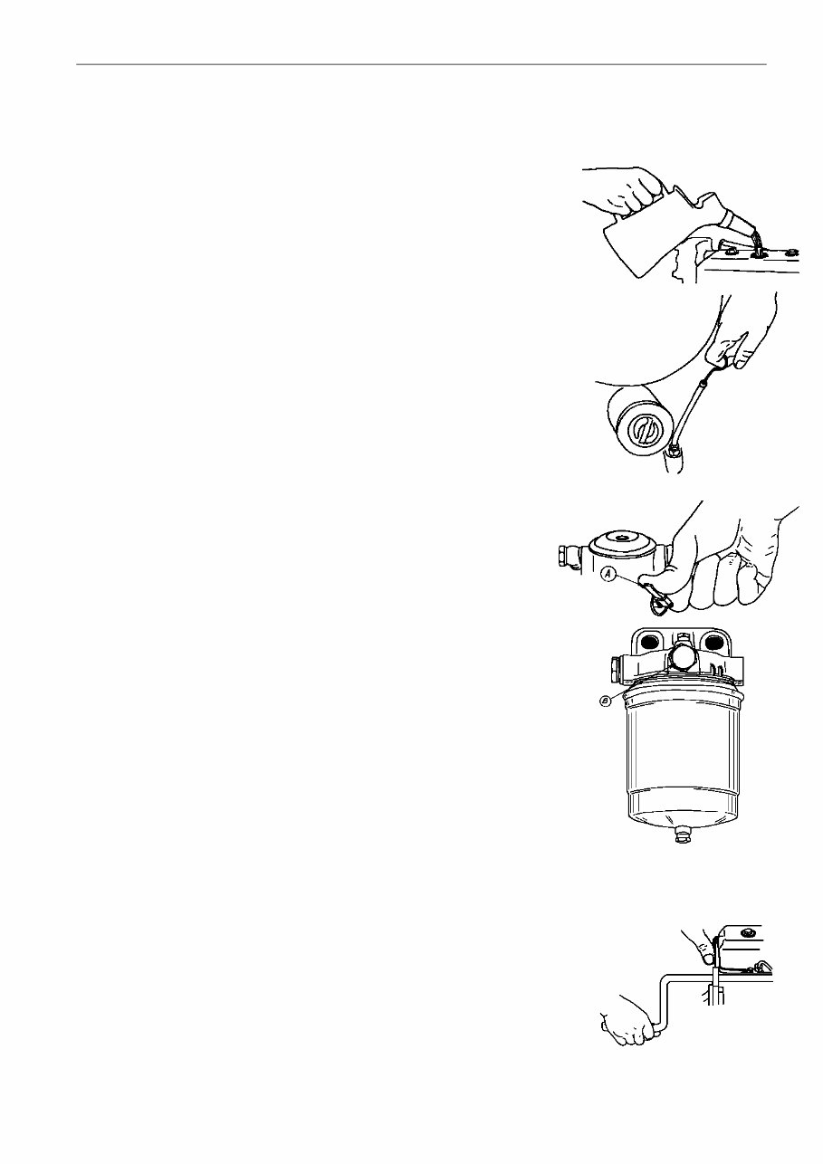
1. Pour lubricating oil through filling hole on top of valve cover.
Check that oil level is between the marks on the dipstick, placed at
the port side of the engine.
Check oil level as mentioned below:
a) remove and wipe dipstick
b) reinsert dipstick in the pipe
c) withdraw dipstick, check oil level.
2. Pour lubricating oil through dipstick hole on the top of reverse- and reduction gear
and check oil level as described in pos 1.
3. Flexible sterntube: Lubricate the stuffing box with sterntube oil (outboard).
Unscrew the filler plug and pour in oil until the bearing is full.
Important:The stuffing box shall under no circumstances be force-lubrica-
ted.
These instructions are only valid for propeller equipment supplied by BUKH.
If other equipment is mounted, we refer to the instructions given for this.
4. We always recommend checking of oil level before start.
5. Fill the fuel tank.
6. Bleed the fuel system in the following way:
a) Loosen the slotted screw B on the fuel filter and pump with the handle A on
the fuel lift pump until the fuel is free from air bubbles and runs out at the
slotted screw.
b) Tighten the slotted screw B and continue pumping with the handle A until
fuel, free from bubbles, runs through the transperent hose from fuel pump to
tank.
You must lock the pumping handle in the upper position when you
have finished pumping.
c) Loosen the fuel pressure pipes at their connection on the fuel valves and turn the engine by the starter motor until
fuel, free from bubbles, runs out from the fuel pressure pipes. Finally
tighten the pipes and the engine fuel system is ready for use.
Normally it will not be necessary to bleed the fuel system before starting but
after changing the fuel filter element or carrying out any work on the fuel system
it should be bled in the following way: Loosen the bleed screw and operate the
hand priming lever on the fuel lift pump until air-free fuel discharges from screw.
Tighten bleed screw. Loosen high pressure pipe unions to injectors and turn
engine until fuel discharges from pipes. Reconnect pipes to injectors. The
engine will start in the normal way.
AFTER THE ENGINE HAS BEEN TAKEN INTO USE
Before start
1. The oil level of the engine should be checked every 14 days or every 25
hours of running as described in ”Preparation before first start”. It is not
necessary to refill oil if the level is between the two marks on the dipstick.
2. The oil level of the reduction gear should be checked every 14 days or every 25
hours of running as described in ”Preparation before first start”.
3. The sterntube stuffing box should be lubricated every 14 days or every 25
hours of running.
4. Check the quantity of fuel in the tank.
Electric start with remote control and instrument panel
1. Switch on the main switch.
2. Put the marine gear in neutral position by means of the control handle.
3. The engine is started by pushing the key and turning it to the right.
The starter should not work for more than 10-15 secs. continuously.
Hand start (optional)
1. Put the gear lever in neutral position.
2. Turn decompression lever on valve cover anti-clockwise as far as possible.
3. Engage starting handle and crank engine as quickly as possible. Release decom-
pression lever quickly by turning lever clockwise while cranking and engine will start.
4. By hand start in cold weather you may achieve an easier start after having cranked
the engine with activated decompression lever before the starting procedure.
Never accelerate a cold engine. Let it get warm first.
OPERATING MANUAL FOR BUKH DV36ME ENGINES
009W0327-R03 - 6 -
After Start
1. When the engine has started, the RPM should be 900-1000 RPM when idling.
2. Check the oil pressure. Normally this should be 2-4.5 bar. With cold engine the RPM should be kept down so that the oil
pressure does not exceed 4.5 bar. When idling at warm engine the oil pressure must not be below 1 bar.
3. Immediately after start the oil pressure warning lamp should go out. During normal operation the lamp should stay off.
4. Make sure that the charging control lamp goes out after the engine has started.
5. Check the cooling water temperature frequently. The temperature should be in the area of 70 – 95
o
C when engine is
warm.
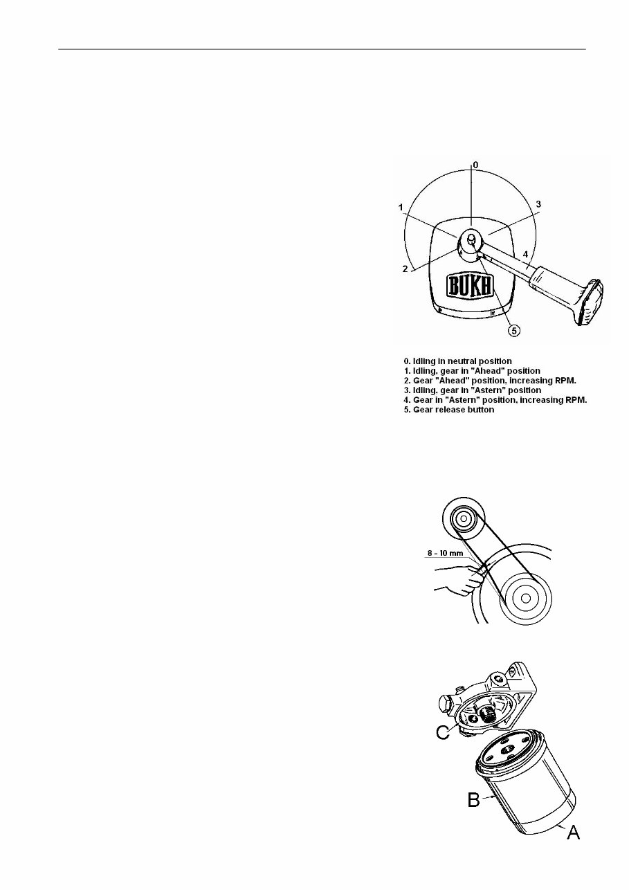
Manoeuvering
1. With the control lever in central position the engine is idling, and the
marine gear is in neutral (pos. 0). When the lever is moved forward in
range 1, the marine gear is engaged to "Ahead” first, and then in
range 2 the engine R.P.M. is increased. When the lever is moved from
the central position to range 3, the marine gear is engaged to "Astern”
first, and then in range 4 the engine R.P.M. is increased.
2. Only engage "Ahead” or "Astern” when the engine is idling.
3. To accelerate engine without engaging gear, operate gear release
button 5 and move control handle in either direction.
4. Increase the load gradually from idling in the course of the first 15-20
minutes shortly after the start of the engine.
Stopping the engine
1. Reduce the load gradually in the course of 15-20 minutes before stop.
2. Reduce the engine to idling and put the gear in neutral position.
3. Turn the ignition key left to stop position, pushing it slightly inwards.
The key must not be left in this position after the engine has stopped
due to the large current consumption of the stop solonoid. In this
position the acoustic alarm will function, when the engine has
stopped.
4. Turn off the battery main switch.
Running in
To secure long life and maximum power it is recommended to run the
engine for the first 25 hours at not more than 80 pct. of the maximum
output (about 3200 r.p.m.)
You should avoid slow hauling as for instance towage. After the first 25
hours it is recommended to change engine and gear oil and to tighten
up the cylinder head and to check or to possibly adjust the tension of the
V-belt. Besides, it is recommended to let an authorized service dealer go
over engine and installation.
MAINTENANCE
Belt for alternator
To be adjusted every 150 hours by turning the alternator round the centres of
suspension. Tensioning should be so as to allow 8 - 10 mm deflection of the belt
under firm thumb pressure.
Air inlet filter
This is a wire gauze filter to be rinsed in petrol and cleaned by a blast of
compressed air after 300 hours' operating.
Fuel filter
A fuel filter is fitted between the fuel lift pump and the H.P. fuel pump. The filter is a
disposable one which cannot be cleaned. It should be changed every 300 operating
hours or if water contamination is suspected.
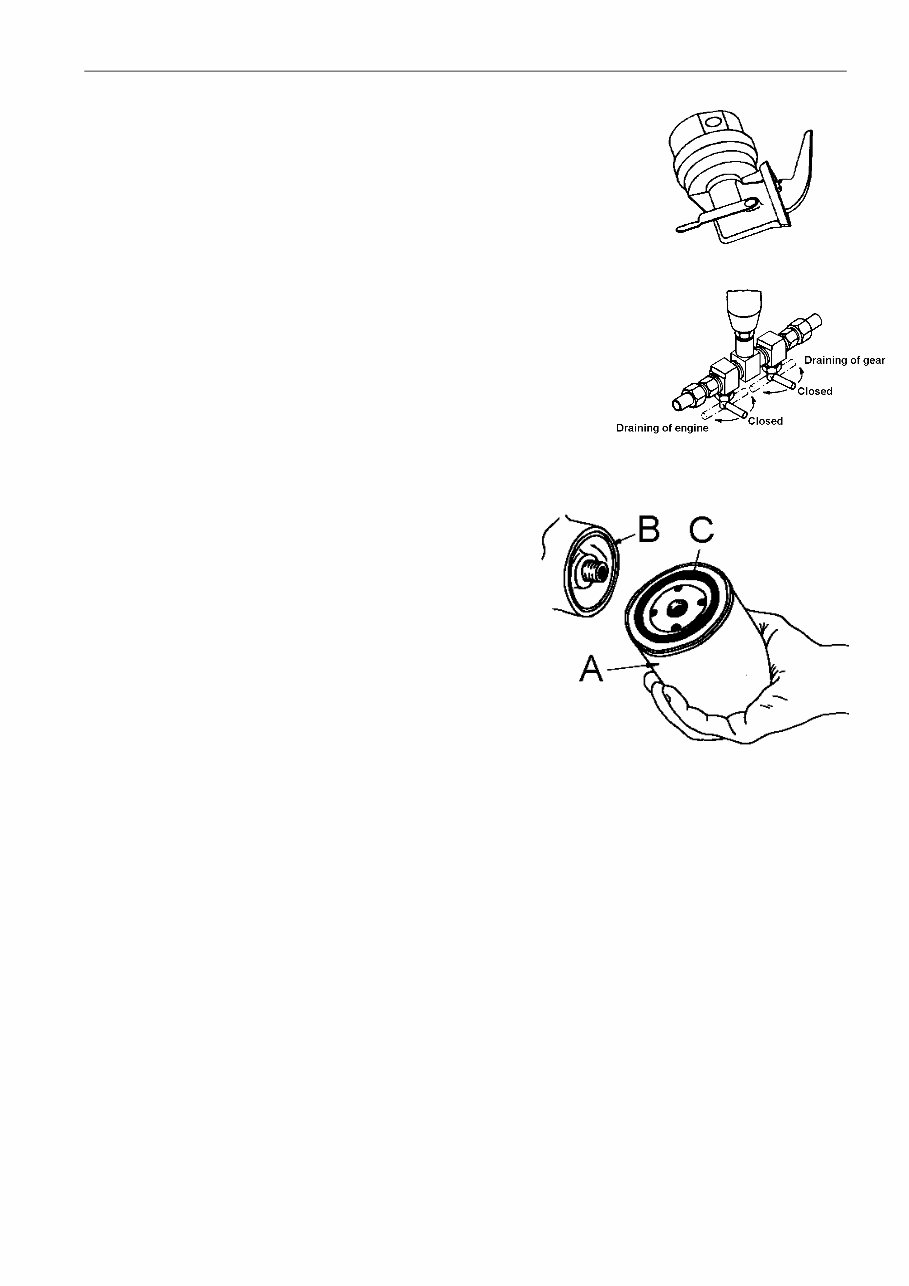
Change the filter as follows:
1. Drain off the fuel from the filter by slackening drain screw A in the bottom of the
filter casing B.
2. Remove by hand or by means of a pair of tongs the filter casing and discard it.
3. Clean the sealing surface of the filter holder C if necessary.
4. Fill the new filter casing with clean fuel through the holes at the top of same.
5. Screw on the filter casing and tighten it by hand about half a turn after the gasket
fits tightly.
6. After changing the filter, bleed the fuel system as stated under ”Preparation for
first start”
OPERATING MANUAL FOR BUKH DV36ME ENGINES
009W0327-R03 - 7 -
Fuel lift pump
The fuel lift pump is a cam shaft driven sealed type diaphragm pump, which cannot be
dismantled for repair or cleaning. It is recommended to install a water/dirt accumulating
filter in the suction line to the pump.
After repairs the fuel system must be bled as described under ”Preparation for the first
start” if necessary.
Lubricating Oil System
The engine is pressure lubricated and the oil system has a built-in relief valve for
controlling the oil pressure. A lubricating oil cooler is also fitted.
The oil level is checked as mentioned before.
Change of Oil
Lubricating oil should be changed for the first time after 25 hours of running,
later for every 150 hours or at least once a year. It is recommended to chan-
ge the oil when engine is warm, and the procedure is as follows:
1. Turn the left cock below oil bilge pump 90°.
2. Pump up the oil from the sump by means of the bilge pump.
3. When the sump is empty pour fresh oil.
4. Check oil level on dipstick.
Recommended Lubricating Oil
Modern diesel engines demand heavy-duty oils with additives securing best
operation conditions and longest life time of the engine under various conditions.
Therefore use a first class HD-oil from a recognized oil company.
Oil specifications as mentioned in ”LUBRICATION OIL CHART”.
When operating under difficult conditions, i.e. frequent cold starting,
short operation periods, greatly varying loads, use quality ”Service
CD” and also use quality "Service CD" in case the sulphur content of
fuel is higher than 1 %.
Change of Lubricating Oil Filter
Lubricating oil filter cannot be cleaned, but should be changed every
150 hours or once a year. To change the filter proceed as follows :
1. Unscrew filter A and discard it.
2. Clean the sealing surface of the engine B, and remove old
gasket C if any from old filter
3. Mount new filter at once under clean conditions.
4. Screw on filter until gasket fits tightly, tighten a further half turn.
5. Fill with oil until normal level is reached.
6. Start the engine and check that the filter is tight.
Cooling water system
Normally the engine is direct seawater-cooled, however, alternatively it can be delivered with freshwater-cooling, or it may
be fitted with this later on. Freshwater-cooling is particularly used in boats running more than 500 hours a year.
Seawater cooling
From external strainer the cooling water is drawn through the lubricating oil cooler to the pump from where the water is fed
through the cooling jackets up to the cylinder head and from there, via the watercooled exhaust manifold and thermostat
overboard, through the exhaust pipe. A thermostat is fitted in the watercooled exhaust manifold. This ensures a constant
cooling-water temperature between 50-75°C
Exchange of zinc anode
In order to protect against corrosion in the engine cooling-water system, there is one zinc anode fitted on the starboard side
of the crankcase under the water-cooled exhaust manifold. The zinc anode must be checked 2-3 times during the season,
dependent on the waters you are sailing in. If the zinc anode is corroded away it must be replaced.
Exchange of impeller in cooling-water pump
The cooling-water pump is a rotary pump with a neoprene impeller. The impeller cannot stand up to dry running for more
than 20 sec., and this is why you must make sure before starting the engine that the sea-cock is open. When building the
boat or during winter storage of the engine, you must not put water pressure to the seawater in-take, as this may fill the
engine cylinders with water. Due to varying temperatures and the one-sided deformation during the winter storage, the
impeller should be taken out and kept separately during this period. Change the impeller by slackening the six screws in the
cover of the pump, remove the cover and withdraw the impeller which is fitted on a multi spline shaft. Too high cooling
temperature (defective pump impeller) or defects on thermostat will cause the blue lamp in the control panel to light up and
the acoustic alarm to function. If the thermostat is removed, the by-pass for cooling water has to be closed.
OPERATING MANUAL FOR BUKH DV36ME ENGINES
009W0327-R03 - 8 -
Freshwater cooling
When using freshwater cooling it will be possible to reach a higher
operating temperature of 70-95°C which will prolong the life of the
engine. This cooling system is recommended for engines operating
for more than 500 hours a year.
A pump circulates the freshwater in a closed system.
This circulation pump is fitted on the back end of the engine. The
fresh water circulates through the cooling jackets of the engine and
through the heat exchanger fitted on the water-cooled exhaust
manifold. The freshwater is cooled in the heat exchanger by
seawater which is pumped through by a big impeller pump like the
one used for direct seawater-cooling.
The seawater leaves the heat exchanger via the exhaust system as
in the case of seawater cooling.
Frost precautions
To avoid damaging the engine, drain the cooling water during frosty
periods.
To protect the engine against damage caused by frost, proceed as
follows:
1. Turn off the cock on the cooling water inlet skin fitting.
2. Drain the cooling water off the engine by removing the plug
above the lubricating oil filter on starboard side and under the
exhaust manifold, respectively.
3. Clean up the drain holes with a nail, a steel wire or the like, so
that any remaining water may drain out.
4. Start the engine and let it run for 30 seconds to remove all the
water from engine and exhaust manifold. Running for that short
time will cause no damage to the impeller of the pump.
On engines fitted with heat exchanger cooling it is recommended to use a mixture of min. 30% antifreeze liquid and 70%
water and max. 50% antifreeze and 50% water as protection against corrosion and to secure the cooling water freezing
temperature to min. minus 15° Celsius or lower if required from climate conditions.
However please also note when doing service on the boat that the mix of water and antifreeze can get aggressive and
start corrosion. If corrosion is found in the cooling system it can be caused by one of two conditions:
1. The anti corrosion additives in the anti freezing liquid are exhausted and have evaporated.
2. Oxidation due to incoming air causing an acid which is lowering the PH value.
Therefore and also to keep the anti freezing properties it is recommended to change the cooling water and antifreeze
every 3 years min. Please also note the details provided by your supplier of antifreeze liquid normally stated on the can.
Heat exchanger freshwater capacity for DV36 is approx. 7.0 litres.
Drain the raw water from the heat exchanger cooled engines by taking off the seawater pump cover.
Electrical System
The engine is equipped with a 12 volt electrical system consisting of a starter motor and an alternator, the max. charging
current of which is 50 Amp.
Electrical wiring diagram for the engine with control and instrument panels is shown later in this instruction.
The level of the electrolyte in the battery should be checked every 14 days or every 25 operating hours. The level should be
5-6 mm above the plates, if this is not the case top up as required with destilled or demineralized water.
The battery must never be isolated from the alternator, when the engine is running.
Warning! It is not allowed to connect additional equipment to the wiring system on the engine. Possible additional
equipment has to be connected directly to the terminals of the battery.
NOTE!
The starter must not be operated for more than 10 sec. If further operation is necessary, a pause of at least half a minute
before starting attempt is repeated.
Marine Gear
The engine is equipped with a reverse-reduction gear. The standard reduction is 3:1 for
AHEAD and 2.5:1 for REVERSE (but also available as 2.5:1 for special purposes).
The marine gear will need no other attendance than regular change of oil. This to be
carried out after 25 hours of operation, and then every 150 hours or once a year.
See oil quality under "Technical data" .
The oil change is carried out by means of the lubricating oil bilge pump fitted on the
engine.
The oil should be warm when draining.
Refill new oil to the quantity of 0.8 liters through the dipstick hole.
Check oil level on the dipstick.
Don’t forget to close the cock before starting up.
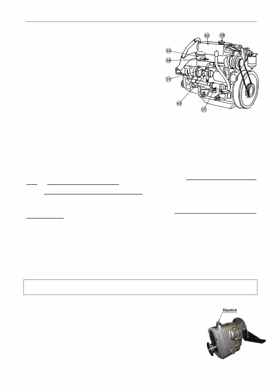
28. Cooling water filling plug
31. Zinc anode
33. Thermostat housing
34. Temperature transmitter
37. Lubricating oil cooler
42. Heat exchanger
43. Cooling water pump
OPERATING MANUAL FOR BUKH DV36ME ENGINES
009W0327-R03 - 9 -
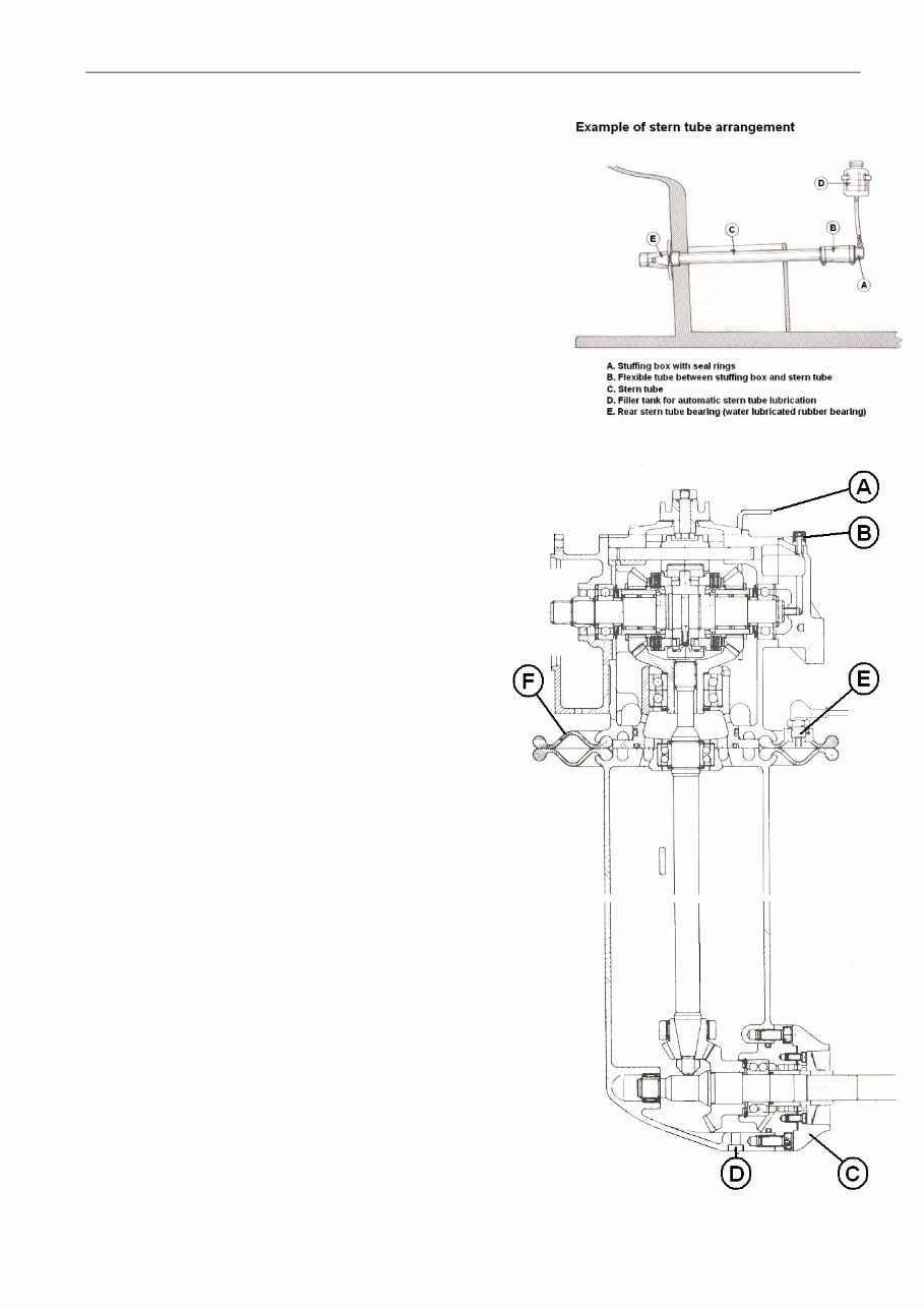
Propeller equipment (As supplied by BUKH – for other types
consult individual manufacturer’s instructions)
Flexible stern tube: Every three years replace the three seal rings in the
stuffing box “A” and the rubber hose “B” connecting stuffing boxand inter-
mediate tube “C” . Fill the flexible stuffing box “A” with Out-board gear oil
through the filler hole in this or via the automatic stern tube lubrication “D”
supplied as extra equipment to the stern tube arrangement.
Normally the consumption of Out-board gear oil is not considerable, and
therefore, a sudden increase indicates defectivesealing rings.
The container “D” should be mounted about 0.25 m above the water line.
Sail drive
As an alternative to the marine gear, the engine can be
equipped with a sail drive. The sail drive has the same
function as the reverse-reduction gear.
The reduction is 2.25:1 for AHEAD and for REVERSE.
The sail drive will need no other attention than regular
change of oil. Change of oil should be carried out after
the first 25 hours of operation, then every 150 hours or
once a year.
Carry out the oil change when the boat is on land by
loosening the screw ”D” in the bottom of the drive,
enabling the oil to run out.
Refill the fresh oil to a quantity of 3.3 ltr. through the filter
hole “B” at the top of the drive corresponding to the
upper mark on the dipstick “A”.
Use the same quality of oil as indicated iunder
“Technical Data” for the marine gear.
A replaceable zinc anode “C” is fitted on the sail drive.
Check this anode once a year, replace it in case of
considerable corrosion.
Only use a propeller which is insulated from the shaft
and the leg!.
Check that there is good electrical connection between
the zinc anode and the bearing hub through the two
mounting screws.
The sail drive is equipped with a double diaphragm “F”
preventing penetration of seawater. In the double
diaphragm a sensor “E” is fitted which releases an
acoustic alarm if water penetrates between the two
diaphragms. It is important for the sake of safety that this
alarm is always serviceable. It should be checked twice
a year by short-circuiting the connections 1 and 2 on the
plastic box next to the multiple plugs.
When short-circuiting here by means of a piece of wire
or a screw-driver, the buzzer should give alarm.
The aluminium housing of the sail drive has been
specially treated on the outside. Damage to surface
treatment should be treated as soon as possible with
special BUKH paint. The sail drive should be coated
with the same paint as the rest of bottom of the boat.
This paint must not contain copper.
OPERATING MANUAL FOR BUKH DV36ME ENGINES
009W0327-R03 - 10 -
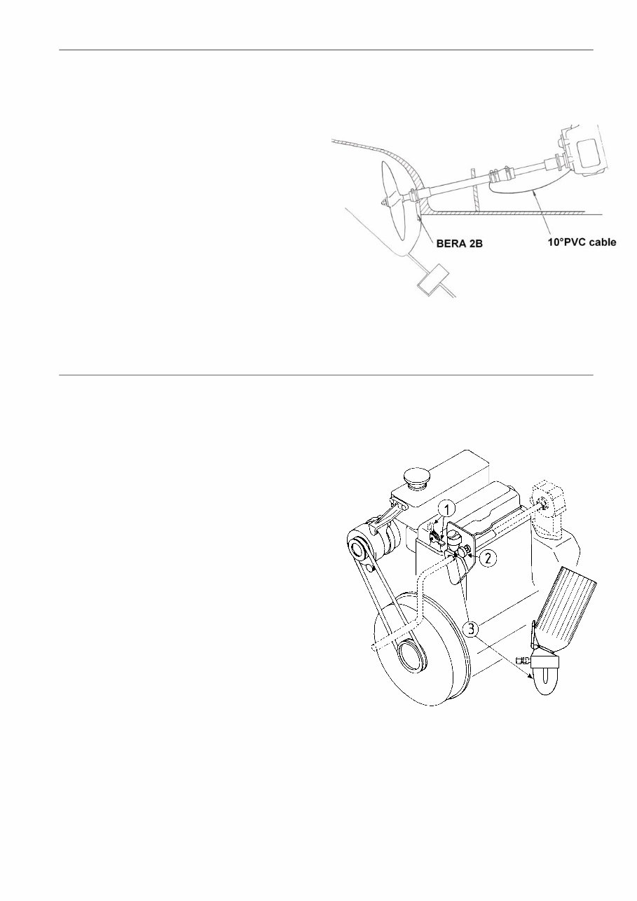
Galvanic corrosion
To avoid corrosion of the propeller due to galvanic action it
is advisable to fit a sacrificial zinc anode on the outside of
the hull. To obtain a high degree of protection, electrical
contact between sacrificial zinc (anode) and propeller
(cathode) has to be established.
This is obtained by fitting the sacrifial zinc and connecting
electrically, as shown on the sketch.
For the DV36 a sacrificial zinc of BERA 2B type is
recommended.
The sacrificial zinc must not be painted or be otherwise
insulated, as this will prevent the zinc from corroding.
The sacrificial zinc must be checked everytime the boat is
ashore, or at least twice a year.
If the corrosion turns out to be very heavy, bigger anodes,
e.g. 2 pcs. BERA 2B or 1 pc. BERA 1, should be fitted. If
there is no corrosion, check the electrical connections. A
good way of fitting the sacrificial zinc is to fold down one of
its flaps and to clamp it to thestern bearing by means of a
rustproof clip as shown on the sketch.
Starting instructions for BUKH Diesel Engine type DV36ME
Electric start:
1. Switch on the main switch.
2. Put the gear into neutral position
3. Turn the start switch to the right
until the engine starts
Hand start (Emergency start):
a. Put the gear into neutral position
b. Put the handle into the crank claw
c. Lift the decompression lever (1)
Only for cold start (below 0
o
C, if mounted):
Start pilot: Pull and push the pump (2) 2-3 times.
d. Turn the starting handle counter-clockwise
as quickly as possible, release the decompression
lever but keep on turning until the engine starts.
Stopping the engine:
Turn the start switch to the left.
After the engine has stopped:
Turn the switch right to neutral position.
Filling the pressure tank (3) (if mounted):
1. Open the cover.
2. Put the gas cylinder on top of the valve and fill up
the tank to max. marking.
You're Reading a Preview
What's Included?
Fast Download Speeds
Online & Offline Access
Access PDF Contents & Bookmarks
Full Search Facility
Print one or all pages of your manual
$36.99
Viewed 88 Times Today


Secure transaction
What's Included?
Fast Download Speeds
Online & Offline Access
Access PDF Contents & Bookmarks
Full Search Facility
Print one or all pages of your manual
$36.99
Our BUKH Diesel Engine Owner User Operator Manual provides essential information for maintaining and repairing DV10M, DV10ME, DV10SME, DV24M, DV24ME, and DV24SME engines. Whether you are a professional mechanic or a DIY enthusiast, this manual is a valuable resource for ensuring the proper functioning of your diesel engine. With detailed instructions and technical specifications, this manual is designed to assist you in performing maintenance and repairs with confidence.
- DV10M
- DV10ME
- DV10SME
- DV24M
- DV24ME
- DV24SME


