

WHIRLPOOL DUET Sport WASHER Repair Service Manual
What's Included?
Fast Download Speeds
Online & Offline Access
Access PDF Contents & Bookmarks
Full Search Facility
Print one or all pages of your manual

L-97
SERVICE MANUAL
WHIRLPOOL & MAYTAG
27” FRONT-LOAD WASHERS
W11169652A

ii
n
Whirlpool & Maytag Front-Load Washers
FORWARD
This Whirlpool Service Manual, (Part No. W11169652A), provides the In-Home Service Professional
with service informaon for the “WHIRLPOOL & MAYTAG 27” FRONT-LOAD WASHERS.”
The Wiring Diagram used in this Service Manual is typical and should be used for training purposes
only. Always use the Wiring Diagram supplied with the product when servicing the washer.
For specific operang and installaon informaon on the model being serviced, refer to the “Use and
Care Guide” or “Installaon Instrucons” provided with the washer.
GOALS AND OBJECTIVES
The goal of this Service Manual is to provide informaon that will enable the In-Home Service
Professional to properly diagnose malfuncons and repair the “WHIRLPOOL & MAYTAG FRONT-LOAD
WASHERS.”
The objecves of this Service Manual are to:
• Understand and follow proper safety precauons.
• Successfully troubleshoot and diagnose malfuncons.
• Successfully perform necessary repairs.
• Successfully return the washer to its proper operaonal status.
WHIRLPOOL CORPORATION assumes no responsibility for any repairs made on our
products by anyone other than authorized In-Home Service Professionals.
Copyright © 2019, Whirlpool Corporaon, Benton Harbor, MI 49022

Whirlpool & Maytag Front-Load Washers
n
iii
TABLE OF CONTENTS
WHIRLPOOL & MAYTAG FRONT-LOAD WASHERS
SECTION 1 — GENERAL INFORMATION
WASHER SAFETY .................................................................................................................................1-2
WHIRLPOOL CONTROL PANEL & FEATURES (HMI IN DOOR MODELS) ..............................................1-3
WHIRLPOOL CONTROL PANEL & FEATURES (CONSOLE MODELS) .....................................................1-4
MAYTAG CONTROL PANEL & FEATURES (CONSOLE MODELS) ...........................................................1-6
DISPENSERS - WHIRLPOOL WASHERS ONLY ......................................................................................1-9
DISPENSERS - MAYTAG WASHERS ONLY ............................................................................................1-9
MODEL & SERIAL NUMBER LOCATION ............................................................................................ 1-10
WIRING DIAGRAM LOCATION .......................................................................................................... 1-10
MODEL AND SERIAL NUMBER NOMENCLATURE ............................................................................ 1-11
CLEANING THE DRAIN PUMP FILTER/DRAINING RESIDUAL WATER ............................................... 1-12
PRODUCT SPECIFICATIONS .............................................................................................................. 1-13
SECTION 2 — DIAGNOSTICS & TROUBLESHOOTING
WHIRLPOOL & MAYTAG DIAGNOSTICS (CONSOLE MODELS) ............................................................2-2
WHIRLPOOL CONTROL PANEL ........................................................................................................2-2
MAYTAG CONTROL PANEL..............................................................................................................2-3
ABBREVIATIONS ............................................................................................................................2-4
DIAGNOSTIC GUIDE .......................................................................................................................2-4
SERVICE DIAGNOSTIC MODE ..........................................................................................................2-4
ACTIVATING SERVICE DIAGNOSTIC MODE ......................................................................................2-4
SERVICE DIAGNOSTIC MENU ..........................................................................................................2-4
HUMAN-MACHINE INTERFACE (HMI) TEST .....................................................................................2-5
SOFTWARE VERSION DISPLAY ........................................................................................................2-5
LOAD TEST AND QUICK SERVICE CYCLE...........................................................................................2-6
LOAD TEST CHART .........................................................................................................................2-6
QUICK SERVICE CYCLE CHART.........................................................................................................2-7
FAULT/ERROR CODES ....................................................................................................................2-8
WHIRLPOOL DIAGNOSTICS (LCD IN DOOR MODELS) ........................................................................2-9
ABBREVIATIONS ............................................................................................................................2-9
DIAGNOSTIC GUIDE .......................................................................................................................2-9
SERVICE DIAGNOSTIC MODE ..........................................................................................................2-9
ACTIVATING SERVICE DIAGNOSTIC MODE ......................................................................................2-9
SERVICE DIAGNOSTIC MODE TESTS .............................................................................................. 2-10
COMPONENT ACTIVATION ........................................................................................................... 2-11
QUICK SERVICE CYCLE .................................................................................................................. 2-12
FAULT/ERROR CODES........................................................................................................................ 2-13
TROUBLESHOOTING GUIDE ............................................................................................................. 2-16
MANUALLY UNLOCKING THE DOOR ................................................................................................ 2-20
SECTION 3 — COMPONENT TESTING
COMPONENT TESTING: SAFETY INFORMATION ................................................................................3-2
WIRING DIAGRAM - WHIRLPOOL WASHER, LCD IN DOOR MODELS ................................................3-3
WIRING DIAGRAM - WHIRLPOOL WASHER, CONSOLE MODELS.......................................................3-4
WIRING DIAGRAM - MAYTAG WASHER, CONSOLE MODELS .............................................................3-5
COMPONENT TESTING .......................................................................................................................3-6
TEST #1: ACU POWER CHECK ..............................................................................................................3-6
ACU BOARD/CONNECTORS & PINOUTS.............................................................................................3-7
TEST #2A: HUMAN-MACHINE INTERFACE (HMI) LCD IN DOOR MODELS ..........................................3-8
TEST #2B: HUMAN-MACHINE INTERFACE (HMI) CONSOLE MODELS ................................................3-9
TEST #3: MOTOR CIRCUIT ................................................................................................................. 3-10
TEST #4: DOOR LOCK SYSTEM .......................................................................................................... 3-11
Continued on next page . . .

iv
n
Whirlpool & Maytag Front-Load Washers
PRODUCT SPECIFICATIONS & WARRANTY INFORMATION SOURCES (inside back cover)
TEST #5: DRUM LIGHT ...................................................................................................................... 3-12
TEST #6: WATER INLET VALVES ......................................................................................................... 3-13
TEST #7: WATER LEVEL SENSOR ....................................................................................................... 3-14
TEST #8: DRAIN/RECIRCULATION PUMP .......................................................................................... 3-15
TEST #9: WASH HEATING ELEMENT.................................................................................................. 3-16
TEST #10: WASH TEMPERATURE SENSOR ........................................................................................ 3-17
TEST #11A: SINGLE DOSE DISPENSER ............................................................................................... 3-18
TEST #11B: OPTIMAL DISPENSER-DOSING PUMP ........................................................................... 3-19
TEST #12A: DRAWER BULK DISPENSER ............................................................................................ 3-20
TEST #12B: DRAWER BULK DISPENSER LEVEL SENSING .................................................................. 3-21
TEST #13: VENT FAN MOTOR ............................................................................................................ 3-22
TEST #14: VENT BAFFLE SOLENOID .................................................................................................. 3-23
TEST #15: DRY HEATING ELEMENT ................................................................................................... 3-24
TEST #16: DRY TEMPERATURE SENSOR............................................................................................ 3-25
TEST #17: DRY BLOWER MOTOR ...................................................................................................... 3-26
SECTION 4 — COMPONENT ACCESS
REMOVING THE TOP PANEL ...............................................................................................................4-2
REMOVING THE REAR PANEL .............................................................................................................4-3
REMOVING THE WATER LEVEL SWITCH .............................................................................................4-4
REMOVING THE RFI FILTER ................................................................................................................4-5
REMOVING THE DRUM LIGHT ............................................................................................................4-6
REMOVING THE DVT FAN/VENT ASSEMBLY ......................................................................................4-7
REMOVING THE WATER INLET VALVES ..............................................................................................4-8
REMOVING THE APPLIANCE CONTROL UNIT (ACU) ..........................................................................4-9
REMOVING THE TOP REAR BRACKET ............................................................................................... 4-10
REMOVING THE WASH HEATER/THERMISTOR ASSEMBLY.............................................................. 4-11
REMOVING THE DRYER HEATING CHANNEL ASSEMBLY ................................................................. 4-12
REMOVING THE CONDENSER DUCT ASSEMBLY .............................................................................. 4-13
REMOVING THE DOOR ASSEMBLY ................................................................................................... 4-14
REMOVING THE DOOR LOCK ASSEMBLY ......................................................................................... 4-15
REMOVING THE FRONT CONSOLE ................................................................................................... 4-16
REMOVING THE FRONT PANEL ........................................................................................................ 4-17
REMOVING THE SINGLE DOSE DISPENSER ASSEMBLY .................................................................... 4-18
REMOVING THE DIRECT DRIVE MOTOR .......................................................................................... 4-19
REMOVING THE BULK DISPENSE ASSEMBLY ................................................................................... 4-20
REMOVING THE DRAIN/RECIRCULATION PUMPS ........................................................................... 4-22
REMOVING THE TUB ASSEMBLY ...................................................................................................... 4-23
SECTION 5 — CONNECTIVITY
INTERNET CONNECTIVITY GUIDE.......................................................................................................5-2
INITIAL SETUP .....................................................................................................................................5-2
DOWNLOAD AND INSTALL WITH TOUCH SCREEN .............................................................................5-2
DOWNLOAD AND INSTALL WITH NON-TOUCH SCREEN ....................................................................5-2
TROUBLESHOOTING GUIDE ...............................................................................................................5-3
WHIRLPOOL & MAYTAG FRONT-LOAD WASHERS
SECTION 3 — COMPONENT TESTING (CONTINUED)
TABLE OF CONTENTS

GENERAL INFORMATION
Whirlpool & Maytag Front-Load Washers
n
1-1
Section 1:
General Information
This secon provides general safety, parts, and informaon for
the “Whirlpool & Maytag Front-Load Washers.”
n Washer Safety
n Whirlpool Control Panel & Features (HMI in Door)
n Whirlpool Control Panel & Features (Console)
n Maytag Control Panel & Features (Console)
n Dispensers – Whirlpool Washers
n Dispensers – Maytag Washers
n Wiring Diagram Locaon
n Model & Serial Number Locaon
n Model & Serial Number Nomenclature
n Cleaning the Drain Pump/Draining Residual Water
n Product Specificaons

1-2
n
Whirlpool & Maytag Front-Load Washers
GENERAL INFORMATION
Washer Safety
You can be killed or seriously injured if you don't immediately
You can be killed or seriously injured if you don't follow
All safety messages will tell you what the potential hazard is, tell you how to reduce the chance of injury, and tell you what can
happen if the instructions are not followed.
Your safety and the safety of others are very important.
We have provided many important safety messages in this manual and on your appliance. Always read and obey all safety
messages.
This is the safety alert symbol.
This symbol alerts you to potential hazards that can kill or hurt you and others.
All safety messages will follow the safety alert symbol and either the word “DANGER” or “WARNING.”
These words mean:
follow instructions.
instructions.
DANGER
WARNING

GENERAL INFORMATION
Whirlpool & Maytag Front-Load Washers
n
1-3
Whirlpool Control Panel & Features (HMI in Door Model)
Not all features and cycles are available on all models.
NOTE: The control panel features a sensive surface that responds to a light touch of your finger. To ensure your selecons are
registered, touch the control panel with your fingerp, not your fingernail. When selecng a seng or opon, simply touch the
appropriate buon.
POWER BUTTON
Touch to power up the washer.
HOME BUTTON
Touch this buon and the LCD screen will show the home
screen, where you can select your cycle, sengs, and
opons..
FAVORITES BUTTON
Stores and accesses your favorite cycles and a history of
your recently run cycles.
LCD SCREEN
Use this screen to select cycle, sengs, opons, etc.
REMOTE ENABLE BUTTON
Download the Whirlpool™ app and follow the instrucons
to connect your washer to your home Wi-Fi network. You
may also visit www.whirlpool.com/connect. In Canada,
visit www.whirlpool.ca/connect. Aſter connecng to WiFi,
touch the REMOTE ENABLE buon any me you want to
use the app. Touching this buon locks out the LCD screen
and you will be prompted with a message about the
washer waing for input from the app. If you want to exit
this mode, touch the REMOTE ENABLE buon again.
START/PAUSE BUTTON
Touch and hold to start, or touch to pause a cycle. When
you start a cycle, the door will lock, the washer will sense
the load size, and the wash cycle will begin.
TOOLS BUTTON
The Tools buon gives access to many other sengs,
ulity cycles, preferences, and informaon (see next
column). Touch the TOOLS buon to access the Tools
screen, which contains the following (you will need
to scroll down with your finger to access all of the
selecons):
1
2
3
4
5
6
7
1 3
2
6
5
7 4
Temperature
WARM
Spin Speed
EXTRA FAST
Auto Dry
Dry
What to Wash
REGULAR
How to Wash
NORMAL
4:28
3:15
Load & Go™ Dispenser 1
Touch this icon to access Load & Go™ Status Dispenser 1 and
choose between; Acve, Disabled (1 Cycle), or Off (Permanently),
and select detergent concentraon of 2X, 3X, 4X, 5X, 6X, and 8X.
Load & Go™ Dispenser 2
Touch this icon to access Load & Go™ Status Dispenser 1 and
choose between; Acve, Disabled (1 Cycle), or Off (Permanently),
choose between Soſtener or Detergent content, and select
detergent concentraon of 2X, 4X, 6X, and 8X.
Control Lock
Touch this icon to lock the controls. Swipe up to unlock.
Mute
Touch this icon to mute or unmute sounds.
Ulity Cycles
Touch this icon to access the following ulity cycles: Drain
& Spin and the Clean Washer with affresh® cycle. Touch the
ulity cycle you wish to use and follow the screen prompts.
NOTE: To get a Rinse & Spin cycle, select Drain & Spin and the
Extra Rinse opon.
Preferences
Touch to access Times and Dates, Sound Volume, Display
Sengs, and Regional. Follow the screen prompts.
WiFi
Touch to access Connect to Network, SAID (Smart Appliance
ID) Codes, Mac Address, and WiFi. Follow the screen prompts.
Info
Touch to access Service & Support, Store Demo Mode, Restore
Factory, WiFi Terms and Condions, and Soſtware Terms and
Condions. Follow the screen prompts.
NOTE: All changes to sengs will remain in effect unl sengs
are changed again.
7 6
1-4
n
Whirlpool & Maytag Front-Load Washers
GENERAL INFORMATION
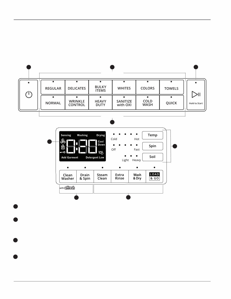
Whirlpool Control Panel & Features (Console Models)
NOTES:
■ Not all features and cycles are on all models.
■ If your model has a touch interface, the control panel features a sensitive surface that responds to a light touch of your finger. To
ensure your selections are registered, touch the control panel with your fingertip, not your fingernail. When selecting a setting or
option, simply touch its name.
■ If your model has physical buttons, make sure to press the button firmly.
■ At cycle completion, your setting and option choices will be remembered for the next cycle. However, if power to the washer is
lost, the settings and options will go back to the factory defaults.
1 2
2
WHAT to wash
HOW to wash
3
Cycles and settings vary by model.
POWER
Select to turn the washer on and off. Select to stop/cancel
a cycle at any time.
WHAT TO WASH/HOW TO WASH
First determine what items are in the load that you are trying
to wash. Use that to guide your “What to Wash” selection.
Then determine how you want the washer to wash them
and make the appropriate “How to Wash” selection.
1
2
Estimated Time Remaining
The Estimated Time Remaining shows the time required for
the cycle to complete. Factors such as load size, modifiers,
options selected, and water pressure may affect the time
shown in the display. Tightly packed loads, unbalanced loads,
or excessive suds may cause the washer to lengthen the
cycle time as well.
Sensing
When Start/Pause is touched the washer will chime,
indicating it is starting. The drum will make a partial turn.
The door will click when it locks.
Once the door has locked, the washer will begin spinning
to sense the load size. This sensing process will continue
throughout the cycle.
After the load size is sensed, the estimated time based
on load size will be displayed and water will be added.
You may hear water flowing through the dispenser,
adding detergent to the load. The actual cycle time may
be lengthened; however, the display will continue to show
the estimated time.
4
7
5
KROG VHF IRU
&\FOH 6LJQDO
KROG VHF IRU
&RQWURO /RFN
KROG VHF IRU
)DQ)UHVK
KROG VHF IRU
3UH6RDN
6
START/PAUSE
Touch and hold for 3 seconds until the light above Start/
Pause comes on to start a cycle, or touch once while a cycle
is in process to pause it.
CYCLE STATUS DISPLAY
The Cycle Status Display shows the progress of a cycle.
At each stage of the process, you may notice sounds
or pauses that are different from traditional washers.
3
4
GENERAL INFORMATION
Whirlpool & Maytag Front-Load Washers
n
1-5
Washing
During the wash cycle, this will display to let you know
the cycle is in progress.
Drying (on some models)
During a drying cycle, this will display to let you know
the drying cycle is in progress.
Cool Down (on some models)
At the end of a drying cycle, your load will go through
a cool-down period.
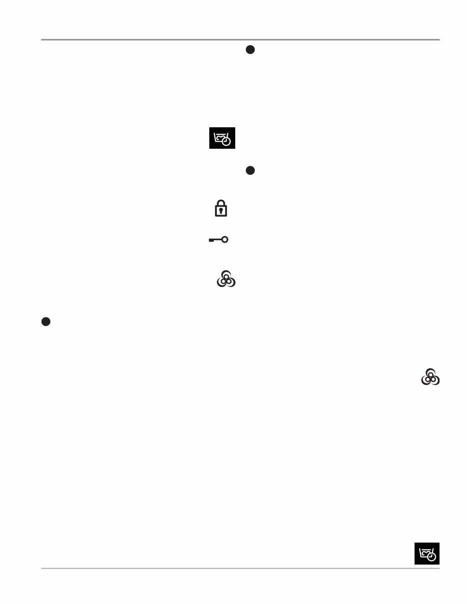
PreSoak
This symbol will be displayed to let you know
a presoak is in progress.
Detergent Low (on some models)
When detergent in the bulk dispenser is running low,
the display will show the detergent level (Low).
Add Garment
When “Add Garment” is displayed, you may pause the
washer, open the door, and add items. Touch and hold
START/PAUSE to start the washer again.
Door Locked
The Door Locked symbol will display to
indicate that the door is locked and cannot
be opened without first pausing or canceling the cycle.
Control Lock
When the Contol Lock symbol is displayed,
the buttons are disabled. Touch and hold EXTRA
RINSE for 3 seconds to enable the buttons.
FanFresh
®
(on some models)
This symbol will be displayed when the FanFresh
®
option is activated. The fan will turn on and the
load will tumble periodically for up to 12 hours.
End
Once the cycle is complete, “End” will display. Remove
the load promptly for best results.
CYCLE MODIFIERS
When you select a cycle, its default settings will light up.
Touch to adjust cycle modifiers on the washer before
touching START/PAUSE. Additional wash modifiers or
options selected after touching Start/Pause may not activate.
Once a wash setting is selected, it is saved for the cycle
selected. To return to factory default cycle settings, unplug
washer for 30 seconds; then plug back in. See “Cycle Guide”
NOTE: Some modifiers may increase or decrease the
estimated time remaining.
Temp
The recommended wash temperature is preset for
each cycle. Some preset temperatures can be changed.
You may select a different wash temperature based on
the level of soil and type of fabric being washed. For
best results, use the warmest wash water safe for your
fabric, following the garment label instructions. All wash
temperatures feature a cold rinse.
Spin
The recommended spin speed is preset for each cycle.
Some preset speeds can be changed.
■ Faster spin speeds mean shorter dry times, but may
increase wrinkling in your load.
■ Slower spin speeds reduce wrinkling, but will leave
your load more damp.
Soil
The recommended soil level is preset for each cycle.
Some preset soil levels can be changed. For heavily
soiled and sturdy fabrics, select the Heavy Soil Level
setting. For lightly soiled and delicate fabrics, select the
Light Soil Level setting. Lower soil level settings will help
reduce tangling and wrinkling.
5
UTILITY CYCLES
Clean Washer
Use this every 30 washes to keep the inside of your
washer fresh and clean. This cycle uses a higher water
level. Use with affresh
®
Washer Cleaner tablets or liquid
chlorine bleach to thoroughly clean the inside of your
washer. When using this cycle, the drum should be
empty. This cycle should not be interrupted. See the
Drain & Spin
This cycle removes excess water from the load or
special-care items washed by hand. Use this cycle
after a power failure. For some fabrics, you may choose
to set a slower spin speed.
and hold DRAIN & SPIN for 3 seconds to set a Dry Only
CYCLE OPTIONS
You may add or remove options for each cycle. Not all
options can be used with all cycles, and some are preset
to work with certain cycles. Options vary by model.
Steam Clean (on some models)
The Steam Clean option adds additional soak and
wash time to many cycles to help remove tough stains,
as well as a steam boost for added cleaning power.
An integrated heater helps to maintain optimal wash
temperatures. See “Cycle Guide” for cycles that allow
You can also touch and hold STEAM CLEAN
for 3 seconds to turn cycle signals on or off.
Extra Rinse
Activate this option to add an extra rinse to most
cycles.
You can also touch and hold EXTRA RINSE
for 3 seconds to disable/enable the Control Lock.
You can also touch and hold WASH & DRY for
3 seconds to activate/deactivate the FanFresh
®
option. Use the FanFresh
®
option if you will be
unable to remove the load promptly. The washer
will automatically activate the fan after the cycle ends
and tumble the load periodically for up to 12 hours.
IMPORTANT:
■ Do not use dryer sheets.
■ Do not dry comforters or large blankets.
Load & Go™ (on some models)
Touch to select this option If you want to automatically
add HE detergent to the wash load at the proper time.
IMPORTANT: When using the dispenser cartridge
with concentrated liquid detergent, be sure to change
the detergent concentration settings in the control if
the detergent used is different than factory preset of
2x concentration. Change the detergent concentration
setting by touching and holding TEMP and SOIL for
3 seconds.
You can also touch and hold LOAD & GO™ for 3
seconds to set a presoak.
PreSoak (on some models)
Touch to add a presoak time of your choice
to a wash cycle.
6
7
Wash & Dry (on some models)
Touch to add a drying cycle to your load aſter the wash
cycle has finished. The Wash & Dry opon is designed
to wash and dry 2-4 lightly soiled synthec garments,
athlec uniforms, or workout wear. This opon has an
extra-high-speed spin followed by intermient tumbling
and fan acvaon to circulate air through the clothes.

1-6
n
Whirlpool & Maytag Front-Load Washers
GENERAL INFORMATION
Maytag Control Panel & Features (Console Models)
Not all features and cycles are available on all models.
NOTES:
■ The control panel features a sensitive surface that responds to a light touch of your finger. To ensure your selections are registered,
touch the control panel with your fingertip, not your fingernail. When selecting a setting or option, simply touch its name.
■ At cycle completion, your setting and option choices will be remembered for your next use of that cycle. However, if power is lost
to the washer, the settings and options will go back to the factory defaults.
3 6
6
A
B
I
D
F
E
2
1
5
4
A
C B
D
F
E
A
C
D
H
G B
3 6
2 1
5 4
6 3 6
2 1
5
4
6
I
I
You're Reading a Preview
What's Included?
Fast Download Speeds
Online & Offline Access
Access PDF Contents & Bookmarks
Full Search Facility
Print one or all pages of your manual
$30.99
$40.99
Viewed 17 Times Today


Secure transaction
What's Included?
Fast Download Speeds
Online & Offline Access
Access PDF Contents & Bookmarks
Full Search Facility
Print one or all pages of your manual
$30.99
$40.99
Get the comprehensive repair service manual for the Whirlpool Duet Sport washer, covering models WFW8300SW, WFW8500SW, and WFW8500SR. This manual is invaluable for both professional mechanics and DIY enthusiasts, providing detailed instructions for all repairs and services required for this washer.
Whether you're using a Mac or Windows computer, this manual offers fast access to the information you need. Securely purchase it using PayPal or credit cards to start saving on repair costs today.


