

COMPLETE BICYCLE Repair Manual
What's Included?
Fast Download Speeds
Online & Offline Access
Access PDF Contents & Bookmarks
Full Search Facility
Print one or all pages of your manual

This chapter has several sections. It should be read
carefully to prepare for using all the other chapters.
The first section is
This section covers only the most
basic and universal terms. The other chapters will
each start with a terminology section with terms that
are more specific.
The second section is Understanding
thread descriptions and thread types is perhaps the
most important basic mechanical skill.
The third section is Press fits are a
means of holding pieces together other than by thread-
ing them. It is a system with its own unique set of
techniques and rules.
The fourth section is Understand-
ing the proper use of greases and oils is critical to be-
ing a good mechanic.
The fourth section is
This section covers what types of cleansers, sol-
vents and polishes might be used, and how to use
them properly.
The last section is This section covers use
of common mechanics tools. The other chapters de-
scribe how to use bicycle mechanic specific tools. A
list of recommended tools is in the appendix.
Chapters on individual component areas of the
bicycle have more specific terminology and definitions.
For the purpose of this manual, the following terms
apply to the frame and basic components.
Frame: The structural piece, usually a number of
tubes joined together, to which all of the components
are attached.
Fork: The structural piece that attaches the frame
to the front wheel. The fork turns to allow the rider
to control the bicycle.
Frame set: The frame and fork combination.
Head tube: The near-vertical tube that is the for-
ward most part of the frame.
Top tube: The upper tube of the frame that ex-
tends back from the head tube to the seat tube.
Down tube: The lower tube of the frame that
extends from the bottom of the head tube to the bot-
tom of the frame (the bottom-bracket shell).
Seat tube: The near-vertical tube that is at the
middle of the frame, which the seat post slides into.
Bottom-bracket shell: The portion of the frame
that contains the crankset bearing parts, which are
called the bottom bracket.
Seat stay: The two tubes of the frame that start
from below the seat and meet the chain stays at the
center of the rear wheel.
Chain stay: The two tubes of the frame that go
from the lower end of the seat tube and meet the seat
stays at the center of the rear wheel.
Dropout: The fittings at the end of the fork, and
at the juncture of the seat stays and the chain stays, to
which the wheels are attached.
Top tube
Seat stay
Chain stay
Bottom-bracket shell
Head tube
Down tube
Fork
Dropout
Dropouts
Seat tube
1.1 Parts of the frameset.
Derailleur: There are two such mechanisms: a
front derailleur and a rear derailleur. The front de-
railleur moves the chain between the selection of gears
on the crankset; the rear derailleur moves the chain
between the selection of gears on the rear wheel.
Chain: The loop of links that connects the front
gears to the rear gears.
Freewheel: The set of rear gears. Freewheels and
freehubs have a confusing overlap of terminology. For
clarification, see the terminology section of the chapter
regarding these items. In a general sense, the freewheel
is the set of gears that the chain turns in order to ap-
ply drive forces to the rear wheel.
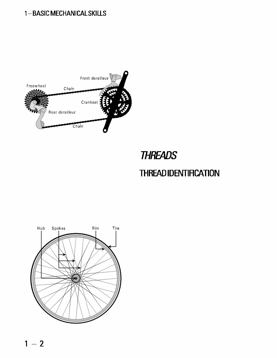
Crankset: The mechanism that is turned by the
riders feet. It consists of two lever arms called crank-
arms, one to three gears called chainrings, and a bear-
ing assembly that the crank arms rotate around called
the bottom bracket.
Bottom bracket: The bearing assembly that al-
lows the crankset to rotate in the bottom-bracket shell.
1.2 Parts of the drivetrain.
Wheel: The assembly consisting of the hub,
spokes, rim, tire and tube.
Hub: The assembly at the center of the wheel that
houses the axle bearings, and to which spokes attach.
Freehub: A hub and freewheel that have been
combined into a single integrated assembly.
Spokes: The tensioned wires that join the hub and
rim together.
Rim: The hoop at the outer edge of the wheel to
which the tire is mounted.
Tire: The rubber hoop at the outer edge of the
wheel assembly.
1.3 Parts of the wheel.
Headset: The bearing assembly that connects the
fork to the frame and allows the fork to rotate inside
the head tube.
Pedal: A mechanism that supports the riders
foot. It contains a bearing assembly and is mounted
to the crank arm.
Seat post: The pillar (usually a tube of metal) that
attaches the seat to the frame.
Saddle: The soft structure that supports the
riders posterior.
Stem: The piece that connects the handlebars to
the fork.
Handlebar: The piece that supports the riders
hands and is turned to control the bike.
Brake lever: The levers that are operated by the
riders hands to control the braking function.
Shift lever: The levers operated by the riders
hands that control the derailleurs.
Brake caliper: The mechanisms that squeeze
against the rims to control the bikes speed.
One of the key challenges to the mechanic is to
be able to replace or upgrade parts with compatible
parts. One of the most significant obstacles to be over-
come is the number of different thread standards used
on bicycles. For example rear axles alone come in seven
different varieties. Threads are described by a two part
number, such as 3/8" × 26tpi or 10mm × 1mm. The
first number refers to the diameter of the male ver-
sion of the thread and the second number refers to
the pitch. When identifying a thread, start with pitch.
The first step to identifying a thread is to measure
the pitch with a pitch gauge. Pitch is a measurement of
the frequency of threads, or the distance from one thread
to the next. In an inch system (BSC and Whitworth),
pitch is measured by the number of threads that occur
in one inch of thread length, and in a metric system
pitch is the distance from one thread to the next.
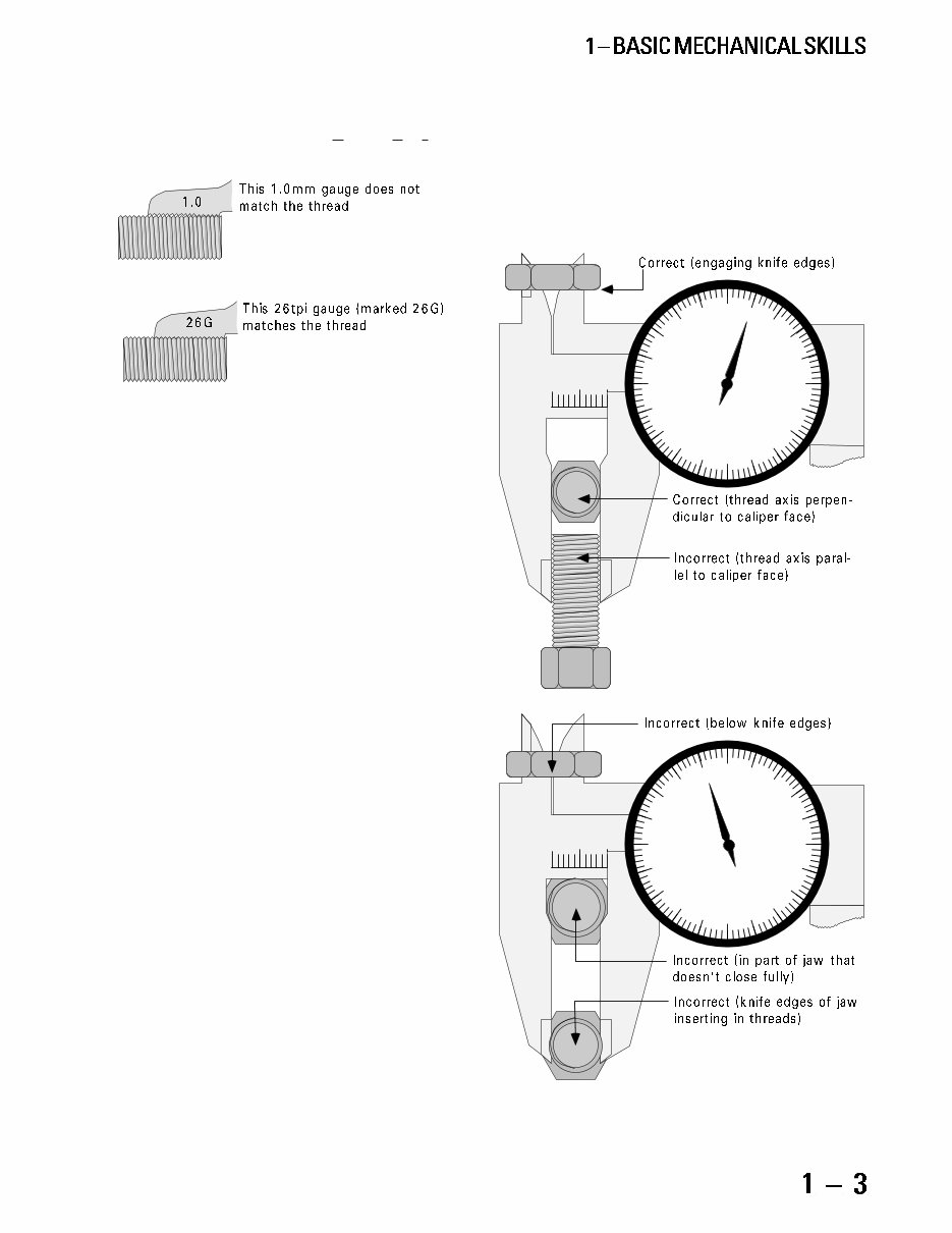
Pitch is measured with a pitch gauge by mating
the gauge to the thread. If the gauge can be held down
in the thread at both ends simultaneously, the thread
is identified (see figure 1.4). The best pitch gauges avail-
able come with both metric and Whitworth gauges.
Although Whitworth is quite rare, Whitworth pitch
gauges are compatible with the BSC (British Standard
Cycle) threads found on many bicycle parts. Although
gauges are not normally marked with the appropriate
units, the thread is metric whenever the number in-
mon BSC freewheel threads. Also, Jou Yu (Joy Tech)
hub axles have metric diameter combined with inch
pitch in some inconsistent cases.
When measuring diameter use a caliper. Measure
the thread with the axis of the thread perpendicular
to the face of the caliper, the axle centered in the cali-
per jaws and not on any slot in the threads.
0 1
0 1
0
0
0
0
.1
.1
.1
.1
.2
.2
.2
.2
.3
.3
.3
.3
.4
.4
.4
.4
.5
.5
.5
.5
.9
.9
.9
.9
.8
.8
.8
.8
.7
.7
.7
.7
.6
.6
.6
.6
1.5 Correct and incorrect ways to measure thread diameter.
cludes a decimal point, and the pitch is in inches when-
ever the number on the gauge is followed by the let-
ter G or the letters TPI (for Threads Per Inch).
1.4 When the teeth of the thread pitch gauge will all go into the
threads simultaneously, then the gauge matches the thread.
The next step to thread identification is to mea-
sure the diameter. Diameter is a measurement of the
male threads outside diameter (O.D.). It is usually a
nominal measurement. A measurement is a nominal
measurement when an actual measurement is rounded
up to an even number. For example, a thread with a
6mm diameter is only nominally 6mm. The actual
diameter is more like 5.9mm.
Metric bicycle threads are available in .5 millime-
ter increments, so always round the actual measure-
ment up to the nearest .5mm to arrive at the nominal
measurement. Inch bicycle threads are available in
minimum 1/16 inch increments, so always round up
to the nearest 1/16 inch or its decimal equivalent to
arrive at the nominal measurement.
Examples:
If the thread measures 5.9mm it is 6.0mm.
If the thread measures .370" it is .375".
If the thread measures 23/64" it is 3/8".
Diameter may be measured in inches or millime-
ters. The best way to determine which units to use is
by measuring the pitch first, because the diameter is
almost always in the same units (a 1.0mm pitch
threaded item is sure to have a metric diameter). The
exceptions are on Italian-manufactured frames, which
have metric diameter and inch pitch on the fork and
in the bottom-bracket shell, and on Italian-made hubs,
which may have metric diameter axles with inch pitch.
Italian bikes will also have this combination of metric
diameter and inch pitch on the freewheel mounting
threads, but in this case it is not an issue because the
Italian thread happens to be compatible with the com-
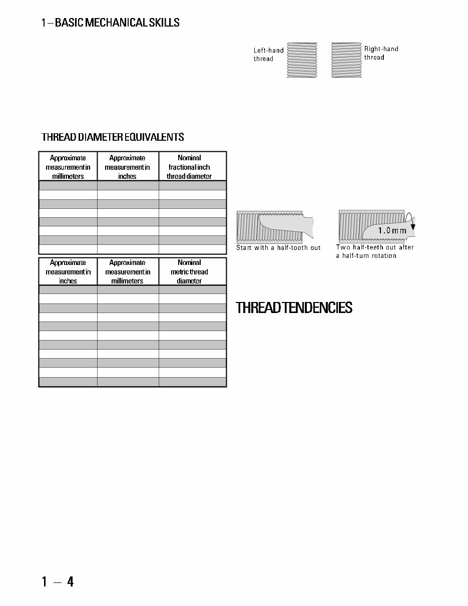
1.6 Whether the thread slopes up to the left or up to the right shows
the thread direction.
Female threads may be identified as left or right
by the following test. Install a matching thread pitch
gauge into the thread in question with exactly one
tooth of the gauge left outside the thread. Rotate the
gauge in the threads at least one-half turn clockwise.
Observe the amount of gauge teeth outside the thread
at this point. If they have increased, it is a left-hand
thread. If they have decreased, it is a right-hand thread.
If the gauge is rotated counterclockwise instead of
clockwise, the results will be opposite.
1.7 Rotate a thread pitch gauge in a female thread to determine
the thread direction.
It is helpful to know what threads are likely to be
encountered in certain situations. The country of origin
of a bicycle frame is likely to determine the thread used in
the bottom bracket and the fork/headset. Different coun-
tries tend to use different thread standards. The standards
are BSC (British Standard Cycle), Metric, Italian
Whitworth, and ISO. ISO stands for the International
Standards Organization. The ISO has adopted many ex-
isting thread descriptions to be the ISO standard. Some of
these existing threads are metric, and some are BSC. ISO
standard threads may have a metric or inch description.
Bicycle frames made in Taiwan, and Japan are cer-
tain to be BSC or ISO thread. Bicycle frames made in
the U.S. are also virtually certain to be BSC or ISO thread,
but sometimes small manufacturers of top end racing
bikes use Italian threads. Bicycle frames made in Italy are
virtually certain to be Italian thread. French bicycles are
the greatest source of confusion because they used to be
French thread, then switched to Swiss thread, and fi-
nally have switched to ISO threading. Bicycle frames from
other countries are seen much more rarely, and it is best
to rely strictly on measurements in these cases. See the
bottom bracket and headset chapters for description of
BSC, ISO, French, Swiss, and Italian threads.
Female thread diameters are rarely provided.
When the pitch is 24tpi, 26tpi, or 1mm the inside
diameter will be approximately .7.9mm less than
the male.
Following is a chart of useful equivalents of thread
diameter. Start by taking a measurement in inches or
millimeters and then look in the right-most column
for the nominal thread diameter.
(table 1-1)
7.7mm .303" 5/16"
9.4mm .366" 3/8"
12.5mm .492" 1/2"
14.1mm .555" 9/16"
25.2mm .992" 1"
28.4mm 1.118" 1–1/8"
31.6mm 1.244" 1–1/4"
34.7mm 1.366" 1–3/8"
.149" 3.8mm 4.0mm
.189" 4.8mm 5.0mm
.228" 5.8mm 6.0mm
.307" 7.8mm 8.0mm
.351" 8.8mm 9.0mm
.346" 9.3mm 9.5mm
.389" 9.8mm 10.0mm
.976" 24.8mm 25.0mm
1.358" 34.5mm 34.7mm
1.370" 34.8mm 35.0mm
1.409" 35.8mm 36.0mm
On all pedals and most bottom-bracket threads
(as well as other rare occurrences), the final aspect of
thread identification is the thread direction. Right-hand
threads (most common) tighten or are installed with a
clockwise rotation and loosen or are removed with a
counterclockwise rotation. Left-hand threads (left ped-
als, some right-hand-side bottom-bracket parts, and
certain freewheel cones and dust caps) tighten or are
installed with a counterclockwise rotation and loosen
or are removed with a clockwise rotation.
Thread direction of male threads may be identi-
fied by observation. Held vertically, the threads on a
right-hand thread will slope up to the right, and the
threads on a left-hand thread will slope up to the left
(see figure 1.6).

The country of origin of a component is useful in
determining the thread type of fittings within the compo-
nent, but the threads that attach a component to another
component or the frame may be unrelated to the country
of origin. For example a bottom bracket made in Japan
for an Italian bicycle would be Italian thread. Another
example would be that an Italian made freewheel installed
as original equipment on an older French bicycle would
probably be a French thread. The threads used within
any Japanese, Taiwanese, or French component are likely
to be metric. The threads used within any Italian compo-
nent are likely to be metric or Italian Whitworth (a bi-
zarre combination of metric diameter and inch pitch).
There is little consistency with U.S. component manufac-
turers to use metric or inch threads. Those U.S. compo-
nent manufacturers that contract to have their products
made in Asia are more likely to use metric threads. For
example, Grip Shift uses metric threads on fittings, but
fittings on Bullseye hubs use inch pitch threads.
The primary form of thread preparation is lubri-
cation. Preparation of threads with oil or grease per-
mits ease of assembly and disassembly. Lubrication
makes it easier to feel when the threaded component
is becoming tight enough. Corrosion is also prevented
by lubrication; however, lubrication is counter effec-
tive on threads with nylon inserts.
In most cases the lubrication choice is between oil
and grease. Oil is generally used on threads of small
diameter or fine pitch. Ease of application is the pri-
mary advantage compared to grease. Grease is used
on threads of larger diameter and coarser threads. Its
advantage over oil is durability under exposure to
moisture and less of a tendency to evaporate.
In some cases it is preferable to use a compound called
Loctite instead of lubrication. Loctite is a liquid that hard-
ens and expands after application. It is not a glue, but
works by expanding to fill a gap and exerting pressure
between the parts. Loctite used on threads aids ease of
assembly, prevents corrosion, prevents threaded com-
ponents from coming loose and consequentially reduces
the need to over-tighten parts, risking their damage.
Loctites generally cure in a few hours. The hard cake
that Loctite compounds cure into is not an adhesive. The
hard cake deteriorates if the threaded item is turned after
curing. Use of Loctite is redundant on threads with ny-
lon inserts. (Loctite is toxic minimize contact.)
There are several grades of Loctite. Some of the
following grades are available from automotive stores
or United Bicycle Tool Supply, but some must be
purchased at industrial bearing supply companies.
Loctite 222 is the lightest grade available and is ap-
plicable on thread diameters up to 6mm. Typical uses
of Loctite 222 include: accessory mounting bolts/nuts,
brake mounting bolts/nuts, and derailleur limit screws.
If only one grade of Loctite were to be used, it
should be Loctite 242. It is heavier than the 222, and
is used on larger diameter threads. Typical uses of
Loctite 242 include bottom-bracket fixed cups and
headset locknuts, but it is also acceptable to use it on
smaller thread diameters.
Loctite 290 is a special application thread locker
that is more heavy-duty than 242, but can be applied
to already assembled components to penetrate into
the threads. Typical uses of Loctite 290 include already
installed accessories (such as fenders) and already in-
stalled bottom-bracket fixed cups.
Loctite 272 or 277 are extremely heavy-duty com-
pounds that would not allow removal without dam-
age to the tool or part. They are used when threads
are damaged and as an alternative to replacement when
permanent installation will not be a problem.
Loctite RC680 serves as a substitute for 272/277
and can be used in other non-thread applications on
the bike, such as enhancing the security of a pressed-
in part like a headset cup.
Loctite 660 (Quick Metal) is not applicable to threads
at all, but will fill gaps for press fits of up to .5mm.
When assembling threads pay close attention to
how they feel. Threads that feel tight during assem-
bly should be checked for:
Thread compatibility
Paint in threads (Clean with tap.)
Damaged threads (Clean with tap, die, thread
chaser or file.)
Cross-threading (Restart thread with better
alignment.)
That threads feel effortless to assemble is not by it-
self an indication of thread compatibility. When the fe-
male thread is a larger diameter than the male, no effort
will be required for assembly, even when there is a pitch
mismatch. If pitch match has not been verified but the
difference between the O.D and I.D. of the parts is ac-
ceptable, then it is acceptable to use test-mating of parts
as a way to determine compatibility. This is a useful tech-
nique in cases where it is impractical to check the pitch
because of small I.D., or short overall thread length.
A thread that gets tight and then feels easier to
turn as it is secured is probably stripping.
Ideally, when threads are damaged the part should
be replaced. If tools are available and the damage is
not too severe, it may be possible to repair the thread.
The best repair will be accomplished with a thread
cutting tool such as a tap (for internal threads) or die
(for external threads). When repairing threads with a
tap or die, first make sure the damaged thread and tap
or die have compatible thread description. Start the
tap or die on the end of the threaded item that is in
the best condition to ensure proper alignment.
If the die is a variety with a split in it so it can be
compressed or expanded, it should be fit in a special
die handle that has expansion and compression adjust-
ers. Thread the die onto the good portion of the thread
with it expanded to a loose fit. Then compress it until
it is barely snug before starting to cut on the threads
that need repair.
An alternative to using a tap or die is to use a thread
chaser. A thread chaser does not actually cut threads.
It does realign threads that have been mangled. It is
most often used on solid axles or the dustcap threads
in crank arms.
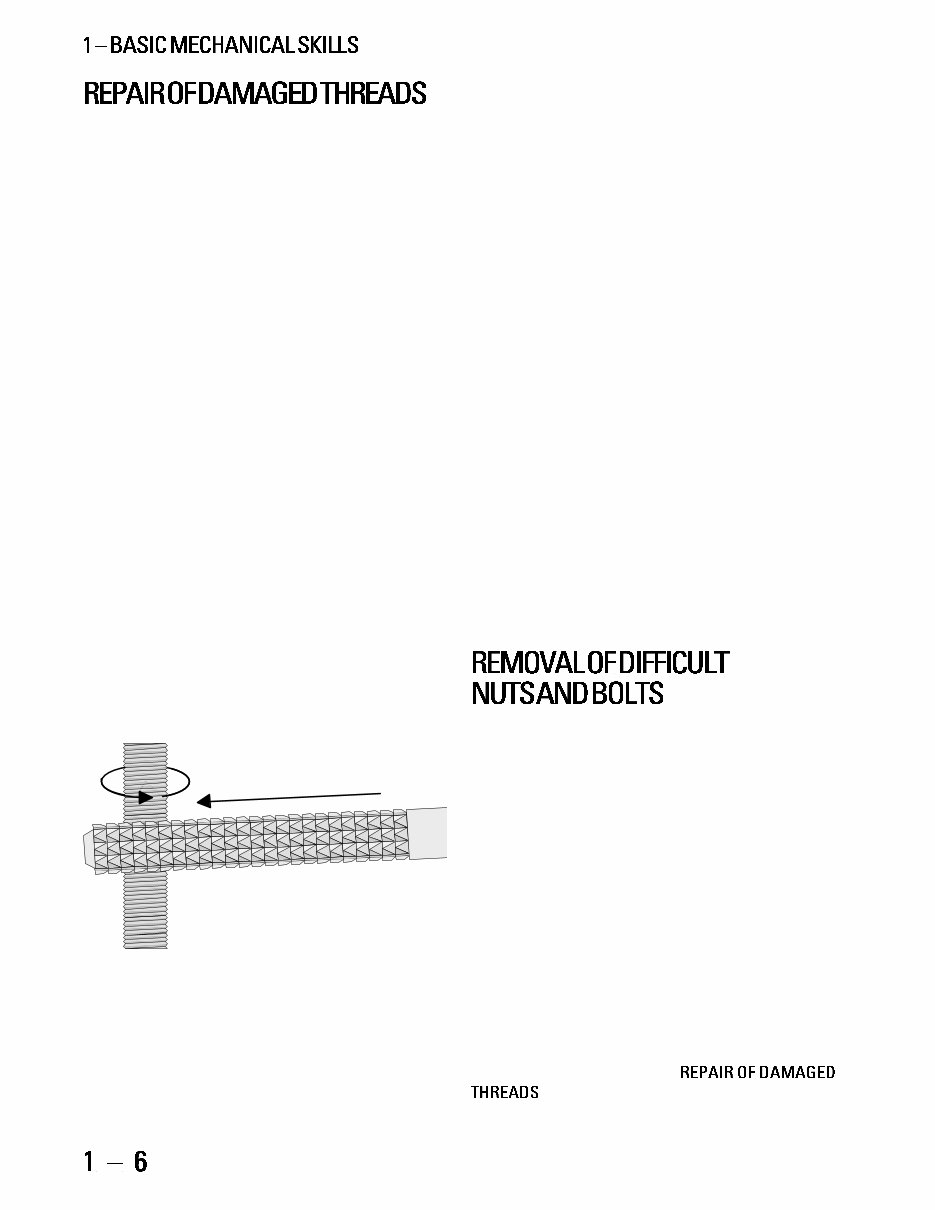
The least expensive way to repair a thread is with
a thread file. The thread file is best when there is just
a small ding in a thread. Thread files can be used on
mangled male threads. Available from various bicycle
tool and general tool suppliers, thread files come in
both inch and metric pitches. After matching the pitch
on the file to the pitch of the thread being repaired,
the file is then stroked in the direction of the thread
angle, while the item being repaired is slowly rotated.
1.8 To use a thread file, match the file pitch to the thread pitch,
then stroke the file at the angle of the thread while rotating the
threaded item.
Stripped threads can sometimes be repaired just
by chasing them with the appropriate tap, die, or
thread chaser. If the thread still does not hold after
this repair, repair options include use of Loctite 277
or RC680, drilling the damaged thread out to a larger
diameter and re-tapping to use a new size, or replac-
ing the damaged part. Using Loctite is a solution only
when there is no further need to remove the part.
Converting to a larger diameter thread may be lim-
ited by available material or parts. Replacing the dam-
aged part has no disadvantage, except cost or limita-
tions of availability.
To repair a stripped thread by going to the next larger
diameter, first drill out the old threads to the appropri-
ate size for the tap that will create the new thread. When
drilling to tap, the use of a larger bit than recommended
will lead to poor thread depth and will probably result
in further thread failure. The use of a smaller bit than
recommended will result in the tap jamming and break-
ing off in the hole. To determine the correct drill size a
simple formula can be used. If it is a metric thread, sub-
tract the pitch from the nominal diameter of the thread;
for example, converting a stripped 4.5mm × .8mm fe-
male thread to 5mm × .8mm requires drilling the hole
out to 4.2mm (5.0 .8 = 4.2). Another example: the
correct tap drill for tapping a 6mm × 1mm thread would
be 5mm (6 1 = 5). For inch thread (which is unlikely
to be needed due to the rare use on inch threads on bi-
cycles), a special or unusual drill bit size is needed. Inch
size threads require tap drills which are unique sizes
that are numbered instead of described by dimension.
After drilling out the hole use the appropriate tap for the
new thread size.
To remove a stubborn nut or bolt first use a pen-
etrating oil and allow to soak for a few minutes. Then
use the best-fitting tool possible. If it is a screwdriver,
apply heavy, downward force while turning the screw.
If a screw or bolt head is deformed in the attempt to
remove it, try vise grips locked securely on the head. If
vise grips fail, use a small saw (Dremel or rotary tool)
to cut a slot in the head to fit a slotted screwdriver.
Another alternative is to file flats on the side of the bolt
or nut head to fit an open-end wrench. If all of the
above fail, the next option is to drill a hole in the bolt
or screw between one-half and three-quarters of the bolt
diameter and then hammer in a screw extractor to turn
out the bolt. The screw extractor is the first option if
the screw or bolt head shears off. The last resort is to
carefully drill the bolt out with the tap drill that is the
appropriate size for the existing thread diameter. The
method for determine the correct size for the drill bit is
covered in the preceding section,
. Then chase the threads out with a tap.
To remove a stripped nut, screw, or bolt that ro-
tates without removing first use penetrating oil. If
possible, grab nut, screw, or bolt with vise grip to pull
up while unthreading. Another alternative is to insert
something like a screwdriver underneath the nut or
screw or bolt head and apply leverage while
unthreading. The last alternative is to use a saw to cut
off the nut, screw, or bolt head.
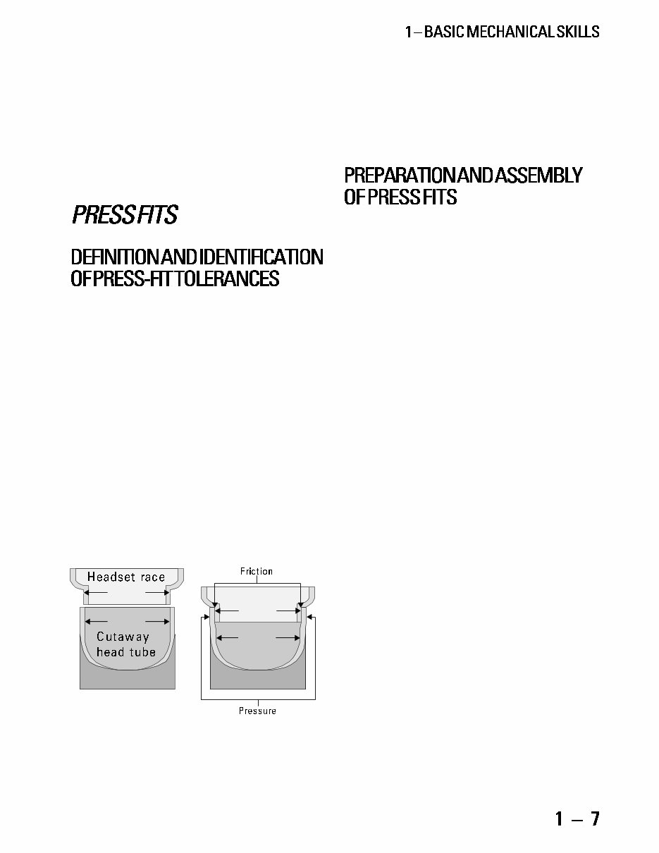
A press fit occurs when one part is inserted into
another with pressure and is held together by the fric-
tion between the mating surfaces.
A common press fit is the interference type. With
an interference type, the fit is accomplished when a
male cylindrical shape is pressed into a smaller hole.
The tolerance between the two parts is generally in
the range of .1.3mm (.004.012"). Examples of inter-
ference press fits include:
Headset races pressed into the head tube
Headset race pressed onto the fork
Dustcaps pressed into hub shells and pedals
Bottom-bracket bearing cartridges pressed into
a bottom-bracket shell
Bearing cups pressed into hub shells and pedals
Cartridge bearings pressed into bottom brack-
ets and hubs
Cartridge bearings pressed into pedals
30.2mm
30.0mm
30.0mm
30.2mm
1.9 These cross-sections show a properly sized headset race before
installation into a head tube, and again after the head tube has de-
flected to accommodate the press fit.
Another type of press fit is the tapered press fit.
In this case the male component is tapered so that the
farther it is pressed in, the tighter it becomes. Examples
of this fit include:
Cotter pins on cotter-type crank arms
Cotterless crank arms that fit on a spindle with
tapered flats
Preparation to install a press fit should include
identifying that the male component is a suitable
amount larger than the female; cleaning the mating
surfaces so that they will be free of lubrication, corro-
sion, and dirt; and treatment with Loctite 222 if pre-
venting corrosion is a concern.
To install press-fit components, a special pressing
tool is often required (see the section of the book that
applies to the particular component in question.) In
the absence of a proper tool, sometimes a vise can be
used, and if that is not suitable, a hammer may be
used. In either case, pay particular attention to the
alignment of the parts as they go in. With a hammer,
use a block of wood or a plastic hammer to protect
the components from damage. With a vise, similar
types of protection may also be required.
Proper installation of tapered-press fits simply
involves pressing the part in hard enough so that it
will hold. Preparation to install tapered-press fits
includes an examination to determine that the length
of engagement is acceptable and cleaning the mat-
ing surfaces, so that they will be free of lubricants,
corrosion and dirt.
For more information and diagrams concerning
tapered press fits see the section of this book regard-
ing crank arms.
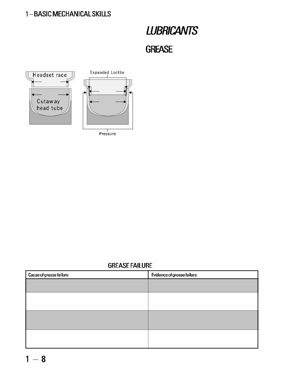
When press fits slip together with little or no ef-
fort, Loctite compounds may be used to improve the
fit. If the fit requires only mild force to install, it will
probably creak or slip under operating conditions, or
moisture may penetrate and cause corrosion, then the
use of Loctite RC680 would be appropriate in most
cases. When installing sealed cartridge bearings (hubs,
bottom brackets, and pedals) Loctite 242 is preferred,
so that removal will not be too difficult. If a press-fit
part slips right in with no effort, but does not jiggle
about once installed, then Loctite RC680 is required
in all cases except for sealed cartridge bearings. Sealed
cartridge bearing installation requires Loctite 242, usu-
ally. If Loctite RC680 is used to improve a marginal
press fit, the fit should be considered as good as new,
except that removal and reinstallation would require
re-application of Loctite. If the press-fit part is loose
Not all greases are suitable for bicycle use. Bicycle
bearings operate in a relatively low temperature range,
so grease designed for automotive use often does not
become effective at bicycle operating temperatures.
Greases made specifically for bicycle use include Phil
Wood, Bullshot, Var, Shimano, Finish Line, Pedros
and Campagnolo. The best automotive grease is a light
grade of Lubriplate.
Grease failure could come at any time. Factory
original greases are often of the lowest quality, and
also are applied in very limited or erratic quantities.
Frames are often inadequately cleaned at the factory,
so bottom-bracket and headset grease is often con-
taminated with abrasives even before the bike has
been ridden. For these reasons it is difficult to project
the normal time or miles between bearing overhauls.
As a soft rule of thumb, 20003000 miles or two to
three years of generally fair-weather riding should
make a bike ready for an overhaul. The best method
to determine whether grease is overdue for replace-
ment is inspection. See table 1-2 below, for causes
and evidence of grease failure.
The container and applicator of grease is as im-
portant as the quality. Open tubs invite contamina-
tion; application from open tubs is messy. Grease is
best used in squeeze tubes or grease guns.
Whether greasing a thread, insertion, or bearing,
an ample quantity of grease will reduce likelihood of
drying and moisture contamination. Wipe excesses
away when assembly is complete.
Grease should be treated like any other unnatural
substance that can penetrate the skin. Minimize expo-
sure or avoid it entirely by wearing disposable latex
painters gloves. Clean hands when exposure is over.
and jiggling after installation, it is best to find a better
fitting part. If a better fitting part is not available,
Loctite RC680 is recommended. Effectiveness may be
limited by how loose the parts are initially, and the
by fact that with press fitting there is no way to en-
sure proper alignment of the parts.
30.05mm
30.0mm
30.0mm
30.2mm
1.10 The headset race and headtube here do not have enough di-
mensional difference to create enough friction; when Loctite RC680
is added before installation, it expands and creates more pressure
(and therefore more friction).
Loctite 660 (Quick Metal) is a thick paste that will
provide security when the male part is up to 1mm
smaller in diameter than the female part. No preci-
sion alignment of the parts is assured, but loose pieces
that cannot be repaired in any other way may benefit
from Quick Metal. A good example would be when
the head tube on a Murray or Huffy juvenile bike
becomes flared and the headset parts are loose and jig-
gling. Because these bikes use non-standard oversized
headset dimensions, there are no practical alternatives
for repair except the use of Loctite 660 (Quick Metal).
(table 1-2)
Age: This is one of the most likely reasons for grease Lack of grease, grease absent from ball path,
to fail, particularly on bikes that see little use. grease caked like half-dry mud.
Internal contamination: This other highly likely cause Light-colored greases turned dark, translucent
of grease failure is caused by particles worn from the greases turned darker and opaque.
bearing surfaces.
Moisture contamination: This cause is only likely Reddish rust color in grease, rust on bearing
when the bike is ridden extensively in wet conditions. parts, water droplets in grease or bearing area.
Colored greases turn a lighter shade.
Dirt contamination: This cause of grease failure is Gritty feeling like sand in the grease, not the
most likely if contaminated grease that has oozed out same as the rough feeling from a tight bearing.
of the bearing is wiped off the wrong way.

Manufacturers of internally-geared hubs recom-
mend special oils that are generally unsuitable for use
elsewhere on the bike. Sturmey Archer Cycle Oil is
one of these, but a suitable replacement would be 10-
weight motor oil.
One of the cleansers needed for proper bicycle
cleaning is an ammonia and water solution for clean-
ing dirt and removing greasy fingerprints. If using a
household cleanser such as 409, Fantastik, or Top Job,
they will leave a soapy film that will need rinsing.
Window-cleaning compounds clean as well and do not
leave a film behind.
For cleaning bearings, drive train components and
any other heavily greased or oily components, choose
between either mineral spirits or non-toxic biodegrad-
able solvents (such as citrus-based solvents.) These are
the environmentally correct alternative to gasoline and
kerosene. If using mineral spirits, avoid excess con-
tact with skin, eyes, and fumes by wearing rubber
gloves, safety goggles, and by working in a well venti-
lated area. Mineral spirits and citrus-based solvents
leave an oily film and are not suitable as a last prepara-
tion before assembling a press fit. Drying time (of
mineral spirits or biodegradable solvents) in confined
areas such as inside chains, freewheels, derailleur and
brake pivots, is quite slow and generally is aided by
blowing with compressed air. If using a biodegradable
solvent, remember that once it is contaminated with
oil or grease it is no longer environmentally friendly.
For certain uses, a more heavy duty solvent (such
as acetone) is needed. Use acetone or rubbing alcohol
when an oil-free surface is required (press fits, braking
surfaces). Use acetone on extremely stubborn dry grease.
Both acetone and alcohol are highly flammable and
volatile, so do not use them around flames or high heat
sources (no smoking). Avoid skin and eye exposure,
and keep fumes to a minimum by disposing of soaked
rags promptly in a fire-safe self-closing metal bucket.
Alcohol is far more environmentally friendly than ac-
etone. There are no biodegradable-type solvents that
perform the same function as these two compounds.
Wax or polish is used to improve the appearance of
paint jobs and to protect them. Most automotive waxes
are suitable for bicycles. Wax should be applied to clean
surfaces with light rubbing. After it dries it should be
wiped off with a soft cloth. Check the label of any au-
tomotive product before using it on the painted surface
of a bicycle. Test products of uncertain suitability on
the bottom of the bottom-bracket shell.
Oil is used on threads, derailleur pivots, brake piv-
ots, lever pivots, the chain, inside freewheels and in-
side internally-geared multispeed hubs.
Not all oils are equally suitable for bicycle use.
The oil needs to be resistant to accumulating grit, du-
rable to exposure to the elements, and light enough to
penetrate into tight areas. These characteristics out-
weigh the significance of any more technical consid-
erations, such as the type of oil base or whether Teflon
is part of the formula. Oils that are specifically suit-
able to bicycle use include:
Phil Wood Tenacious Oil
Triflow
Bullshot
Superlube
Campagnolo
Allsop
Finish Line
Pedros
Lube Wax
The oils at the top of this list are generally more
suited to use in wet conditions while oils that appear
lower down on the list are more suitable for use in
dry, dusty conditions.
Popular oils that are specifically unsuitable for
most bicycle applications include:
WD40
Sewing machine or gun oil
3-in-1 oil
Motor oil
Method of application is very important with oils.
Aerosols are environmentally unfriendly and usually
lead to excessive application. The only exception to
the problem of excessive application is with spray lu-
bricants that are designed to dry in a matter of min-
utes after application (such as Finish Line and Allsop
oils), but these may be the worst offenders environ-
mentally. In general, oils used in external applications
should be used sparingly to avoid dripping and dirt
accumulation, and excesses should always be wiped
off immediately. Overall, the best form of applica-
tion is from drip applicators. They are economical to
use as well, because waste is limited.
In addition to their value as lubrication, oils are
also used to facilitate disassembling frozen threaded
components. Special penetrating oils perform this
function best. Triflow, Allsop, and some other bicycle
oils are somewhat effective for penetration.
This section covers the proper use of common tools
that are not unique to bicycle mechanics. This section
also covers the use of the bicycle repair stand. There is
a comprehensive list of common tools and bicycle spe-
cific tools in the appendix. The types of tools and con-
cepts covered in this section are as follows:
Box- and open-end wrenches
Ratchet drives and sockets
Torque and torque wrenches
Adjustable wrenches
Pliers and vise grips
Screwdrivers
Utilizing mechanical advantage
Hammers
Hacksaws
Files
Grinder
Drilling
Taps
Using repair stands
Always use the smallest wrench that will fit. A
16mm cone wrench seems to fit on a hub cone with
15mm flats, but a 15mm wrench is the smallest that
will fit. It may be possible to turn a 15mm cone with
a 16mm wrench, but it is likely to damage the nut and
the wrench.
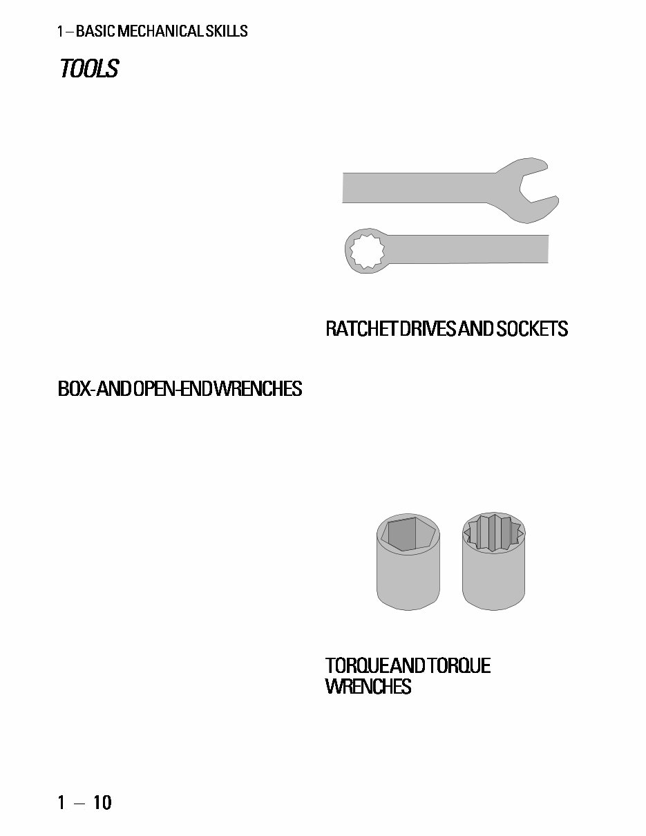
Box- and open-end wrenches are non-adjustable
wrenches that are made in specific sizes that are sup-
posed to closely match the fittings they will be used on.
They come in inch and metric sizes. Metric sizes are
most common for bicycles. Certain inch and metric
sizes are interchangeable in one direction only (because
the substitute is only slightly over-sized). These are:
13mm wrench on 1/2" fitting
14mm wrench on 9/16" fitting
16mm wrench on 5/8" fitting
Open-end wrenches contact the fitting at only two
points, making them inclined to round off nuts, espe-
cially if they are held in poor alignment to the fitting.
Their advantage is access from the side of the fitting
when access from the end is difficult. They also gen-
erally allow a more flush fit against surfaces adjacent
to the fitting, so are well suited to low-profile nuts
and bolt heads.
Box-end wrenches enclose the fitting and contact
it at six points, reducing the likelihood of rounding
the fitting under heavy load or poor alignment and
fit. Their limitation is with low-profile fittings, or fit-
tings with no access from the end. Box-end wrenches
come in six-point and twelve-point configurations. The
six-point configuration is more durable and has better
purchase (surface engagement), but twelve-point
wrenches are quicker to get positioned on the fitting.
1.11 Open-end wrench on top, box-end wrench below.
Ratchet drives enable working faster because they
do not require removal of the wrench on the return
stroke. Good applications of a socket and ratchet drive
include crank-arm bolts, brake-mounting nuts, axle
nuts, and seat-post binder nuts.
Socket wrenches (which can be fitted to a ratchet
drive, torque wrench, or socket driver, or may come
prefixed on certain spanners) are similar in their ad-
vantages to box-end wrenches, but even more useful
when there is limited or no side access to the fitting,
such as with crank-arm-mounting bolts.
1.12 Six-point socket (left) and twelve-point socket (right).
Torque is a measurement of a forces tendency to
produce torsion and rotation about an axis, used most
often in bicycle mechanics to describe the tightness of
You're Reading a Preview
What's Included?
Fast Download Speeds
Online & Offline Access
Access PDF Contents & Bookmarks
Full Search Facility
Print one or all pages of your manual
$36.99
Viewed 63 Times Today


Secure transaction
What's Included?
Fast Download Speeds
Online & Offline Access
Access PDF Contents & Bookmarks
Full Search Facility
Print one or all pages of your manual
$36.99
This is a comprehensive Bicycle Repair Manual covering all aspects of bike repair. The manual contains 685 pages filled with detailed information and blown-up diagrams.
- Basic Mechanical Skills
- Tapping Bottom-Bracket-Shell Threads
- Facing the Bottom-Bracket Shell
- Reaming and Facing the Head Tube
- Milling the Fork Crown
- Sizing and Threading Fork Columns
- Seat Tube Milling
- Frame and Fork Alignment and Damage
- Adjustable Bottom Brackets
- Cartridge Bearing Bottom Brackets
- Headsets
- Adjustable Cone Hubs
- Cartridge Bearing
- Wheel Building and Rim Replacement
- Wheel Truing and Repair
- Wheel Removal, Replacement, and Installation
- Tires and Tubes
- Taper-Fit Crank Arms
- Cottered Crank Arms
- One Piece Cranks
- Chainrings
- Pedal Removal, Replacement, and Installation
- Freehub Mechanism and Thread On Freewheels
- Chains
- Chainline
- Handlebars, Stems, and Handlebar Extensions
- Seats and Seatposts
- Shift-Control Mechanisms
- Derailleur Cable Systems
- Rear Derailleurs
- Front Derailleurs
- Brake Levers
- Brake Cable Systems
- Cable Operated Rim Brake Calipers
- Hydraulic Rim Brakes and Disk Brakes
- Suspension Forks and Rear Shocks
Total Pages: 685
Format: PDF
Language: English
Compatible: Win/Mac
This manual is useful for both professional mechanics and DIY enthusiasts. It contains numerous pictures and diagrams, and all pages are printable for convenience. Save money by performing your own repairs with these easy-to-follow, step-by-step instructions. Instant access means no shipping costs or waiting for a CD to arrive in the mail. For any manual-specific questions or needs, feel free to email us, and we will be happy to assist you promptly. Thank you for visiting our homepage on tradebit.


