Cummins Onan OTPCA OTPCB OTPCC OTPCD Transfer Switch 40-1000 Amperes Service Repair Manual INSTANT
What's Included?
Lifetime Access
Fast Download Speeds
Online & Offline Access
Access PDF Contents & Bookmarks
Full Search Facility
Print one or all pages of your manual
Caution: This document contains mixed page sizes (8.5 x 11 or 11 x 17), which may affect printing. Please adjust your printer settings according to the size of each page you wish to print.
OTPC Transfer Switch 40 to 1000 Amperes Printed in U.S.A. 962–0516A 10-2002 Service Manual
vi OTPC-1 Safety Precautions This manual includes the following symbols to indi- cate potentially dangerous conditions. Read the manual carefully and know when these conditions exist. Then take the necessary steps to protect per- sonnel and the equipment. DANGER This symbol warns of immediate hazards that will result in severe personal injury or death. WARNING This symbol refers to a hazard or unsafe practice that can result in severe per- sonal injury or death. CAUTION This symbol refers to a hazard or unsafe practice that can result in personal inju- ry or product or property damage. ELECTRICAL SHOCK CAN CAUSE SEVERE PERSONAL INJURY OR DEATH High voltage in transfer switch components pres- ents serious shock hazards that can result in severe personal injury or death. Read and follow these suggestions. Keep the transfer switch cabinet closed and locked. Make sure only authorized personnel have the cabi- net and operational keys. Due to the serious shock hazard from high voltages within the cabinet, all service and adjustments to the transfer switch must be performed only by an electrician or authorized service representative. UTILITY-TO-GENSET OR GENSET-TO-GENSET APPLICATIONS If the cabinet must be opened for any reason: 1. Move the operation selector switch on the gen- erator set to Stop. 2. Disconnect the battery charger. 3. Disconnect the starting batteries of the genera- tor set or sets (remove the ground [–] lead first). 4. Remove AC power to the automatic transfer switch. If the instructions require otherwise, use extreme caution due to the danger of shock hazard. UTILITY-TO-UTILITY APPLICATIONS If the cabinet must be opened for any reason, re- move AC power to the automatic transfer switch. If the instructions require otherwise, use extreme caution due to the danger of shock hazard. GENERAL PRECAUTIONS Place rubber insulative mats on dry wood platforms over metal or concrete floors when working on any electrical equipment. Do not wear damp clothing (particularly wet shoes) or allow skin surfaces to be damp when handling any electrical equipment. Jewelry is a good conductor of electricity and should be removed when working on the electrical equipment. Wear safety glasses whenever servicing the trans- fer switch and and do not smoke near the batteries. Do not work on this equipment when mentally or physically fatigued, or after consuming alcohol or any drug that makes the operation of equipment un- safe. WARNING INCORRECT SERVICE OR REPLACEMENT OF PARTS CAN RESULT IN DEATH, SEVERE PERSONAL INJURY, AND/OR EQUIPMENT DAMAGE. SER- VICE PERSONNEL MUST BE QUALIFIED TO PERFORM ELECTRICAL AND/ OR MECHANICAL SERVICE.
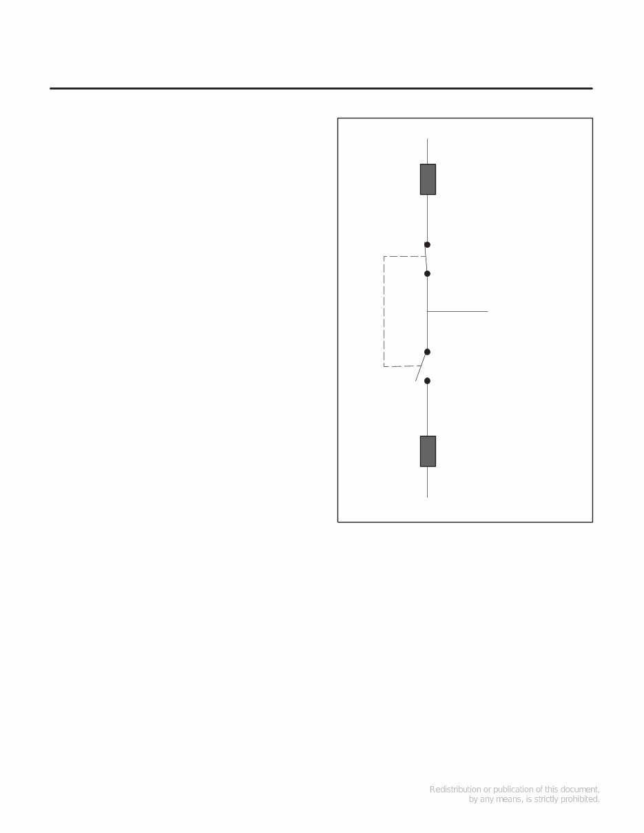
1-1 1. Introduction ABOUT THIS MANUAL This manual contains service procedures for an OTPC automatic transfer switch (ATS). This is an open transition (OT) transfer switch with Power- Command Control (PC). With an open transition switch there is never a time when both sources are supplying power to the load. Refer to the schematic and wiring diagram package that was shipped with the ATS for specific informa- tion about its configuration. Use normal and necessary safety precautions be- fore starting any service procedure. Identify all haz- ards by referring to the Safety Precautions and ob- serve all warnings and cautions within the manual. Whenever you are troubleshooting, remember that the generator set, ATS, and utility power source are all interdependent. TRANSFER SWITCH APPLICATIONS Transfer switches are an essential part of a build- ing’s standby or emergency power system. Power Source 1 (Normal), commonly the utility line, is backed up by Power Source 2 (Emergency), often a generator set. The transfer switch automatically switches the electrical load from one source to the other. The load is connected to the common of the ATS (Figure 1-1). Under normal conditions, the load is supplied with power from Source 1 (as illustrated). If Source 1 is interrupted, the load is transferred to Source 2. When Source 1 returns, the load is re- transferred to Source 1. The transfer and retransfer of the load are the two most basic functions of a ATS. PowerCommand is a registered trademark of Onan Corporation. LOAD NORMAL EMERGENCY OVERCURRENT PROTECTIVE DEVICE OVERCURRENT PROTECTIVE DEVICE FIGURE 1-1. LOAD TRANSFER SWITCH (TYPICAL FUNCTION) UTILITY-TO-GENSET CONTROL OPERATION In utility-to-genset applications, the transfer switch performs the following functions: 1. Sense the interruption of the Source 1 power. 2. Send a start signal to the generator set (Source 2). 3. Transfer the load to the Source 2. 4. Sense the return of Source 1. 5. Retransfer the load to Source 1. 6. Send a stop signal to the generator set.
1-2 UTILITY-TO-UTILITY CONTROL OPERATION In utility-to-utility applications, the transfer switch performs the following functions: 1. Sense the interruption of the Source 1 power. 2. Transfer the load to the Source 2. 3. Sense the return of Source 1. 4. Retransfer the load to Source 1. Level 2 controllers can control a two-utility configu- ration for prime power. One utility is designated the preferred source. The control automatically trans- fers the load between the two utilities and detects alarm conditions. The exercise routine is not avail- able in this configuration. The operator can select either source as the pre- ferred source. See the Digital Display Menu System section. GENERATOR-TO-GENERATOR CONTROL The genset-to-genset control can be set up for two types of applications: • Prime Power – Two gensets provide all of the power (utility power is not available) • Dual Standby – Two gensets are used to back up utility power Note: The Test/Exercise function and Load Shed feature are not available in this configuration. If one genset fails to operate within the specified range of voltage and frequency, the transfer switch automatically starts and connects the other genset. Preferred Source Selection With both prime power and dual standby applica- tions, either genset can be set up to be the preferred source. If the preferred source is changed while one of the gensets is running, the control starts the sec- ond genset and transfers the load to it, when it be- comes available. Time Delays All the time delays are factory set and are adjust- able through the front panel display. The factory set- tings are: TDNE 10 SEC TDEN 600 SEC TDESa 3 SEC TDECa 600 SEC TDESb 3 SEC TDECb 600 SEC Note: TDESa and TDECa are for the Source 2 gen- set and TDESb and TDECb are for the Source 1 genset. Use the Time Delay sub-menus under Setup or the PC Service tool to change the settings. Prime Power (Plant to Plant) Operation In prime power applications, utility power is not available. The system includes one transfer switch and two gensets. One genset is always running and supplying power to the load while the other genset is the backup genset. An external power supply is not needed in this application. Preferred Source Selection – Under normal op- eration, one genset is designated as the preferred source and supplies power to the load. The second genset is the backup power source. If the preferred genset fails, the backup genset starts and the trans- fer switch transfers the load to the backup genset. At any time, the PC Service tool or the Test sub- menu can be used to designate either genset (Source 1 or Source 2) as the preferred genset. If the preferred genset is changed and the backup genset becomes the preferred genset, the transfer switch transfers the load to the new preferred gen- set when it becomes available. The unit that is car- rying the load is always considered the preferred source. Automatic Changeover – The transfer switch can be set up to change the preferred source automati- cally by enabling the changeover timer. The Time Delay sub-menus under Setup or the PC Service tool can be used to enable the changeover timer and specify a changeover delay time period. The automatic changeover timer automatically changes the preferred source and transfers the load to the new preferred genset after a TDEN time delay. After the transfer is complete, the control initi- ates a cool-down period (TDEC) on the old pre- ferred genset before shutting it down. The old pre-
Cummins Onan OTPCA OTPCB OTPCC OTPCD Transfer Switch 40-1000 Amperes Service Repair Manual is an electronic manual that provides comprehensive maintenance information for professional mechanics and DIY enthusiasts. This manual offers a significant advantage over its paper counterpart, allowing users to zoom in on any part of the content for clear visibility on a computer.
The manual covers a wide range of topics including safety precautions, introduction, component description, operation, display menu system, events, troubleshooting, transfer switch service, and schematics. It is meticulously written in a step-by-step format, making it easy for users to perform repairs on their own and potentially save on expenses.
The manual is available in a file format compatible with all versions of Windows and Mac. It is in English and requires Adobe Reader for access.
Recently Viewed
5,521,897Happy Clients
2,594,462eManuals
1,120,453Trusted Sellers
15Years in Business
Price:
Actual Price:
Cummins Onan OTPCA OTPCB OTPCC OTPCD Transfer Switch 40-1000 Amperes Service Repair Manual INSTANT