

Onan KV Microlite 2800 Series Generator Complete Workshop Service Repair Manual
What's Included?
Fast Download Speeds
Online & Offline Access
Access PDF Contents & Bookmarks
Full Search Facility
Print one or all pages of your manual
w
MicroLite'" 2800 Series
Printed in U.S.A.
981 -0506
3-91 (Spec A & B)
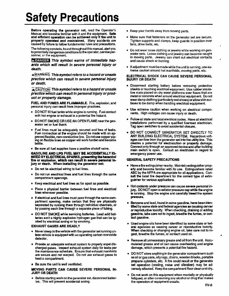
Safety Precautions
Before operating tho generator set, read the Operator's
Manual and become familiar with it and the ui ment. Safe
proper1 operatad and malntalned. Many accidents are
The following symbols. found throughout this manual, alert you
to potentiall dangerousconditionsto the operator, service per-
and etnclent opontlon can be achieved on 77 y f the unlt Is
caused ?I y failure to follow fundamentalrules and precautions.
sonnel. or t x e equipment.
Thls symbol warns of lmmedlate haz-
anis whlch wlll result In seven? personal lnjuty or
death.
A+W-AFINING~ Thls symbol refers to a hazard or unsafe
practlce whlch can result In severe personal lnjqf
or death.
&CAUTION? - _.__ Thls symbol refers to a hazard or unsafe
- - .
practice which can result In personal InjuIy or prod-
uct or property damage.
FUEL AND FUMES ARE FLAMMABLE. Fire, explosion, and
personal injury can resutt from improper practices.
DO NOT fill fuel tanks while engine is running. Fuel contact
with hot engine of exhaust is a potential fire hazard.
DO NOT SMOKE OR USE AN OPEN FLAME nearthe gen-
orator set or fuel thank
Fuel lines must be adequately secured and free of leaks.
Fuel connection at the engine should be made with an ap-
provedflexible, nor~~nductive line. Do not use copper pip-
ing on flexible lines as copper will work harden and become
bnttle.
Be sure all fuel supplies have a positive shutoff valve.
GASOLINE AND LPG FUEL MAY BE ACCIDENTAUY IG
NmED BY ELECTRICALSPARKS, rumntlngthr huardof
Jury or death. Whon lnrtalllng tho generator set:
fln or explosion, whkh an rosu P t In savere p ond In-
Do not tie electrical wiring to fuel lines.
Do not run electrical lines and fuel lines through the same
compartment openings.
Keep electrical and fuel lines as far apart as possible.
Place a physical barrier between fuel lines and electrical
lines wherever possible.
If electrical and fuel lines must pass throughthe same com-
partment opening, make certain that they are physically
ssparated by ruming them thrwgh individual channels, or
by passing each line through a separate piece of tubing.
DO NOT SMOKE while servicing batteries. Lead acid bat-
teries emit a highly explosive hydrogen gas that can be ig-
nited by eiectricai arcing or by smoking.
EXHAUST GASES ARE DEADLY
0 Never sleep in the vehicle with the generator set running un-
less vehicle is equipped with an operating carbon monoxide
detector.
Provide an adequate exhaust system to properly expel dis-
charged gases. Inspect exhaust system daily for leaks per
the maintenanceschedule. Ensure that exhaust manifokls
are secure and not warped. Do not use exhaust gases to
heat a compartment.
Be sure the unit is well ventilated.
MOVING PARTS CAN CAUSE SEVERE PERSONAL IN-
JURY OR DEATH
Beforestarting work on the generator set. disconnect batter-
ies. This will prevent accidental arcing.
Keep your hands away from moving parts.
0 Make sure that fasteners on the generator set are secure.
Tighten supports and clamps. keep guards in position over
fans, drive belts, etc.
0 Do not wear loose clothing or jewelry while working on gen-
erator sets. Loose clothingand jewelry can become caught
in moving parts. Jewelry can short out electrical contacts
and cause shock or burning.
0 If adjustment must be made while the unit is running, use ex-
treme caution around hot manifolds, moving parts, etc.
ELECTRICAL SHOCK CAN CAUSE SEVERE PERSONAL
INJURY OR DEATH
I
I
Disconnect starting battery before removing protective
shields or touching electricalequipment. Use rubber insula-
tive mats placed on dry wood platforms over floors that are
metalor concretewhen around electrical equipment. Do not
wear darnpclothing (particularlywet shoes) orallawskin sur-
faces to be damp when handling electrical equipment.
Use extreme caution when working on electrical compo-
nents. High voltages can cause injury or death.
FoUowall state and local electrical codes. Have all electrical
installations performed by a qualified licensed electrician.
Tag open switches to avoid accidental closure.
DO NOT CONNECT GENERATOR SE3 DIRECTLY TO
ages can flow from the generator set intothe utility line. This
croates a potential for electrocution or property damage.
Connect onlythrough an approved device and after building
main switch is open. Consult an electriaan in regard to
emergency power use.
ANY BUILDING ELECTRICAL SYSTEM. Hazardous volt-
GENERAL SAFETY PRECALmONS
Haveafire extinguishernearby. Maintainextinguisher prop-
erly and become familiar with its use. Extinguishers rated
ABC by the NFPA are appropriate for all applications. Con-
dt the local fire department for the meet type of extin-
guisher for various applications.
Hot codants under pressure can cause severe personal in-
jury. DO NOTopen a radiator pressurecap w hii th4 engine
b running. Stop the engine and carefully Meed the system
-e-
Benzene and lead. f w n d in some gasdine, have been iden-
tified by some state and federal agencies as causing cancer
orreproductive toxicity. When checking, draining or adding
gasoline. take care not to ingest, breathe the fumes, or con-
tact gasdine.
Used engine oils have been identified by some state or fed-
eral agencies as causing cancer or reproductive toxicity.
When chec#ng or changing engine oil. take care not to in-
gest, breathe the fumes. or contact used oil.
Removeall unnecessary grease and oil from the unit. Accu-
mulated grease and oil can cause overheating and engine
damage, which presents a potential fire hazard.
DO NOTstore anything in the generator compartment such
as oil or gas cans, oily rags, chains, wooden blocks, portable
propane cylinders, etc. A fire could resuH or the generatoi
set operation (cooling, noise and vibration) may be ad.
versely affected. Keep the compartment floor clean and dry.
Do not work on this equipment when mentally or physically
fatigued, or after consuming any alcohol or drugthat makes
the operation of equipment unsafe.
RV-8
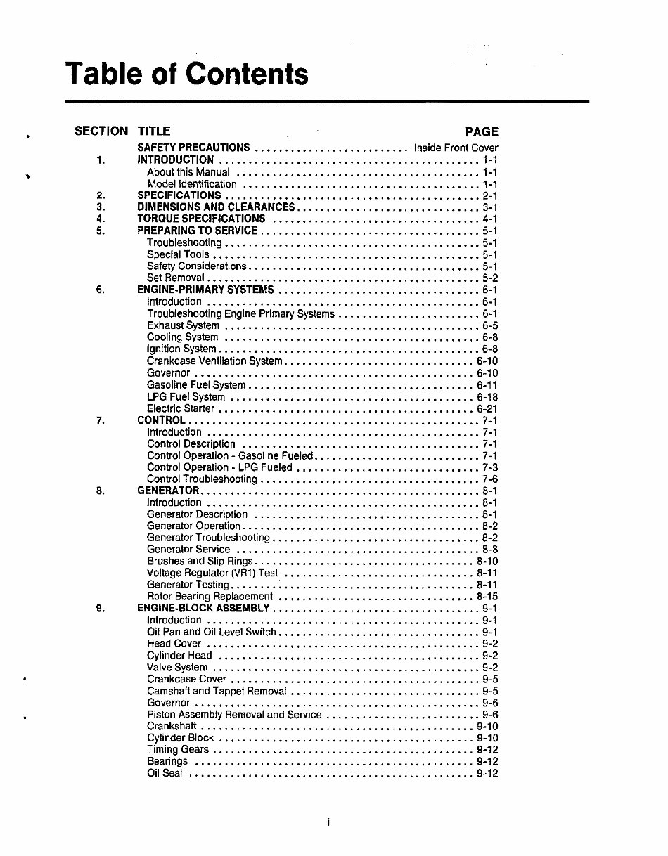
Table of Contents
SECTION
1 .
2 .
3 .
4 .
5 .
6 .
7 .
8 .
9 .
TITLE PAGE
SAFETY PRECAUTIONS .......................... Inside Front Cover
INTRODUCTION ............................................ 1-1
About this Manual ......................................... 1-1
Model Identification ........................................ 1-1
SPECIFICATIONS ........................................... 2-1
DIMENSIONS AND CLEARANCES ............................... 3-1
TORQUE SPECIFICATIONS ................................... 4-1
PREPARING TO SERVICE ..................................... 5-1
Troubleshooting ........................................... 5-1
SpecialTools ............................................. 5-1
Safety Considerations ....................................... 5-1
Set Removal .............................................. 5-2
ENGINE-PRIMARY SYSTEMS .................................. 6-1
Introduction .............................................. 6-1
Troubleshooting Engine Primary Systems ........................ 6-1
Exhaust System ........................................... 6-5
Cooling System ........................................... 6-8
ignition System ............................................ 6-8
Crankcase Ventilation System ................................ 6-10
Governor ............................................... 6-10
Gasoline Fuel System ...................................... 6-11
LPG Fuel System ......................................... 6-18
Electric Starter ........................................... 6-21
CONTROL ................................................. 7-1
Introduction .............................................. 7-1
Control Description ........................................ 7-1
Control Operation - Gasoline Fueled ............................ 7-1
Control Operation - LPG Fueled ............................... 7-3
Control Troubleshooting ..................................... 7-6
GENERATOR ............................................... 8-1
Introduction .............................................. 8-1
Generator Description ...................................... 8-1
Generator Operation ........................................ 8-2
Generator Troubleshooting ................................... 8-2
Generator Service ......................................... 8-8
Brushes and Slip Rings ..................................... 8-10
Voltage Regulator (VR1) Test ................................ 8-11
Generator Testing ......................................... 8-11
Rotor Bearing Replacement ................................. 8-15
ENGINE-BLOCK ASSEMBLY .................................. -9-1
introduction .............................................. 9-1
Oil Pan and Oil Level Switch .................................. 9-1
Head Cover .............................................. 9-2
Cylinder Head ............................................ 9-2
Valve System ............................................. 9-2
Crankcase Cover .......................................... 9-5
Camshaft and Tappet Removal ................................ 9-5
Governor ................................................ 9-6
Piston Assembly Removal and Service .......................... 9-6
Crankshaft .............................................. 9-10
Cylinder Block ........................................... 9-10
Timing Gears ............................................ 9-12
Bearings ............................................... 9-12
OilSeal ................................................ 9-12
Table of Contents
SECTION TITLE PAGE
10 . SERVICE CHECKLIST ........................................................... 10-1
General ......................................................................... 10-1
Mounting ....................................................................... 10-1
Lubrication ..................................................................... 10-1
Wiring .......................................................................... 10-1
Initial Start Adjustments ........................................................ 10-1
Output Checks ................................................................. 10-1
Exhaust System ................................................................ 10-1
Fuel System .................................................................... 10-2
Control ......................................................................... 10-2
Mechanical ..................................................................... 10-2
ii
Section 1 Introduction
I
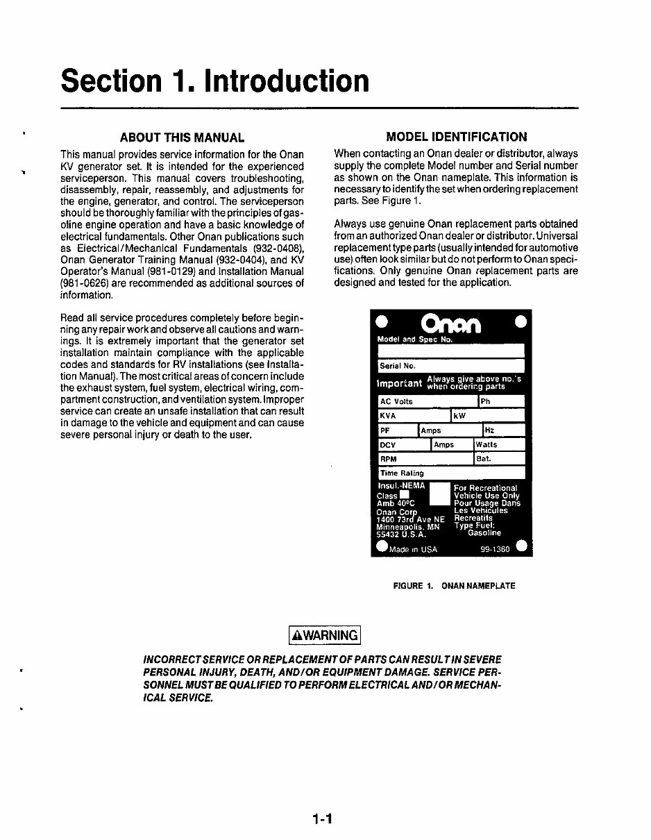
ABOUT THIS MANUAL
This manual provides service information for the Onan
KV generator set. It is intended for the experienced
serviceperson. This manual covers troubleshooting,
disassembly, repair, reassembly, and adjustments for
the engine, generator, and control. The serviceperson
should be thoroughly familiar with the principles of gas-
oline engine operation and have a basic knowledge of
electrical fundamentals. Other Onan publications such
as Electrical/Mechanical Fundamentals (932-0408),
Onan Generator Training Manual (932-0404), and KV
Operator’s Manual (981 -01 29) and Installation Manual
(981 -0626) are recommendedas additional sources of
information.
I
MODEL IDENTIFICATION
When contacting an Onan dealer or distributor, always
supply the complete Model number and Serial number
as shown on the Onan nameplate. This information is
necessaryto identifythe set when ordering replacement
parts. See Figure 1.
Always use genuine Onan replacement parts obtained
from an authorized Onan dealer or distributor. Universal
replacementtype parts (usually intendedfor automotive
use)often look similar but do not Derformto Onan speci-
fications. Only genuine Onan ieptacement
designed and tested for the application.
parts are
Read all service procedures completely before begin-
ning any repair work and observe all cautions and warn-
ings. It is extremely important that the generator set
installation maintain compliance with the applicable
codes and standards for RV installations (see Installa-
tion Manual).The most critical areas of concern include
the exhaust system, fuel system, electrical wiring, com-
partment construction, and ventilation system. Improper
service can create an unsafe installation that can result
in damage to the vehicle and equipment and can cause
severe personal injury or death to the user.
l AWARNING I
H Serial NO. I
PF Amps Hz
FIGURE 1. ONAN NAMEPLATE
INCORRECTSERVICE OR REPLACEMENT OF PARTS CAN RESULTIN SEVERE
PERSONAL INJURY, DEATH, AND/OR EQUIPMENT DAMAGE. SERVICE PER-
SONNEL MUSTBE QUALIFIED TO PERFORM ELECTRICALAND/OR MECHAN-
ICAL SERVICE.
1-1

.
Section 2. Specifications
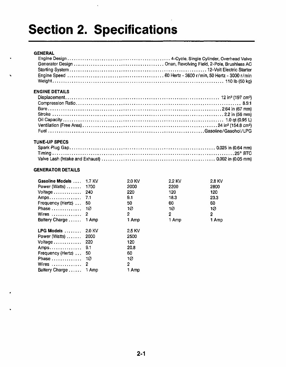
GENERAL
.
Engine Design. ............................................... 4-Cycle, Single Cylinder, Overhead Valve
Generator Design .......................................... Onan, Revolving Field, 2-Pole, Brushless AC
Starting System ............................................................... .12-V0lt Electric Starter
Engine Speed ............................................ .60 Hertz . 3600 r/min, 50 Hertz - 3000 r/min
Weight.. .............................................................................. 110 Ib (50 kg)
\
ENGINE DETAILS
Displacement.. ...................................................................... 12 ins (197 cm3)
Compression Ratio.. ........................................................................... 8.51
Bore.. .............................................................................. .2.64 in (67 mm)
Stroke ............................................................................... .2.2 in (56 mm)
Oil Capacity.. ......................................................................... 1.0 qt (0.95 L)
Ventilation (Free Area). ............................................................. .24 in2 (154.8 cm2)
Fuel ......................................................................... Gasoline/Gasohol/LPG
TUNE-UP SPECS
Spark Plug Gap.. .................................................................. 0.025 in (0.64 mm)
Timing.. .................................................................................. .25" BTC
Valve Lash (Intake and Exhaust) ..................................................... 0.002 in (0.05 mm)
GENERATOR DETAILS
Gasoline Models .... 1.7 KV 2.0 KV 2.2 KV 2.8 KV
Power (Watts) ....... 1700 2000 2200 2800
Voltage ............. 240 220 120 120
Amps.. ............. 7.1 9.1 18.3 23.3
Frequency (Hertz) ... 50 50 60 60
Phase .............. 10 10 10 10
Wires .............. 2 2 2 2
Battery Charge.. .... 1 Amp 1 Amp 1 Amp 1 Amp
LPG Models ........
Power (Watts) .......
Voltage .............
Amps. ..............
Frequency (Hertz) . . ,
Phase ..............
Wires ..............
Battery Charge ......
2.0 KV
2000
220
9.1
50
10
2
1 Amp
2.5 KV
2500
120
20.8
60
10
2
1 Amp
2-1

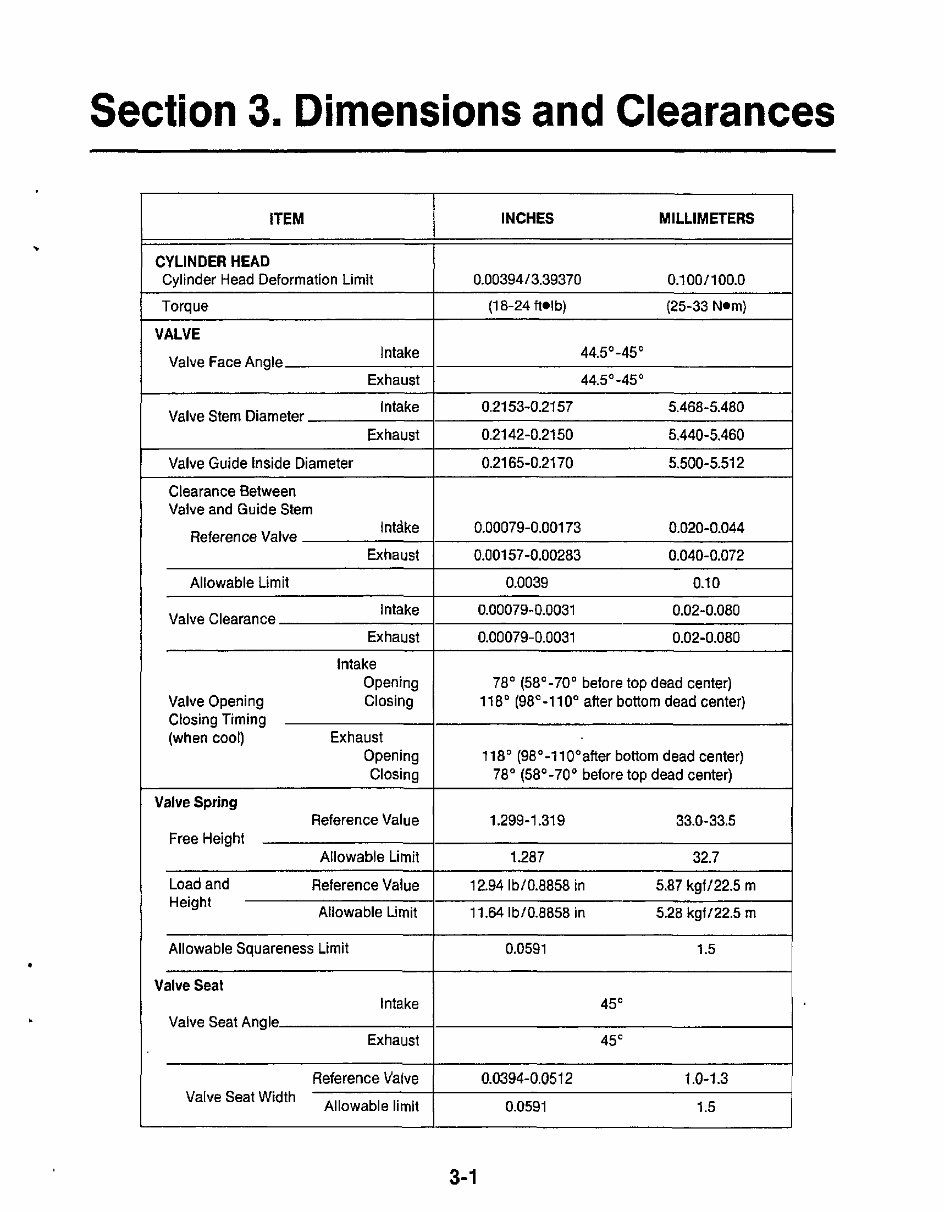
ITEM
CYLINDER HEAD
Cylinder Head Deformation Limit
Section 3. Dimensions and Clearances
INCHES MILLIMETERS
0.00394/3.39370 0.1001100.0
Allowable Limit
Intake
Exhaust
Valve Clearance
Torque I (18-24 ftolb) (25-33 Nom)
0.0039 0.1 0
0.00079-0.0031 0.02-0.080
0.00079-0.0031 0.02-0.080
Intake 44.5"-45'
44.5" -45"
VALVE
Valve Face Angle
0.0591 1.5
0.2153-0.21 57 5.468-5.480
Exhaust 0.2142-0.2150 5.440-5.460
Valve Stem Diameter
Valve Guide Inside Diameter I 0.2165-0.21 70 5.500-5.512
Valve and Guide Stem
Clearance Between
Reference Valve
Intake 0.00079-0.001 73 0.020-0.044
0.001 57-0.00283 0.040-0.072
Intake
Opening
Valve Opening Closing
Closing Timing
(when cool) Exhaust
Opening
Closing
78' (58'-70' before top dead center)
118' (98"-110° after bottom dead center)
118' (98'-110°after bottom dead center)
78" (58"-70' before top dead center)
Reference Value 1.299-1.319 33.0-33.5
i Allowable Limit 1.287 32.7
Valve Spring
Free Height
Reference Value 12.94 Ibf 0.8858 in 5.87 kgff 22.5 m
11.64 lb/0.8858 in 5.28 kgfl22.5 m
Load and
Height
0.0591 1.5
I
Allowable Squareness Limit
Valve Seat
Intake
Exhaust
Valve Seat Angle
45"
45"
Reference Valve I 0.0394-0.051 2 1.0-1.3
3-1
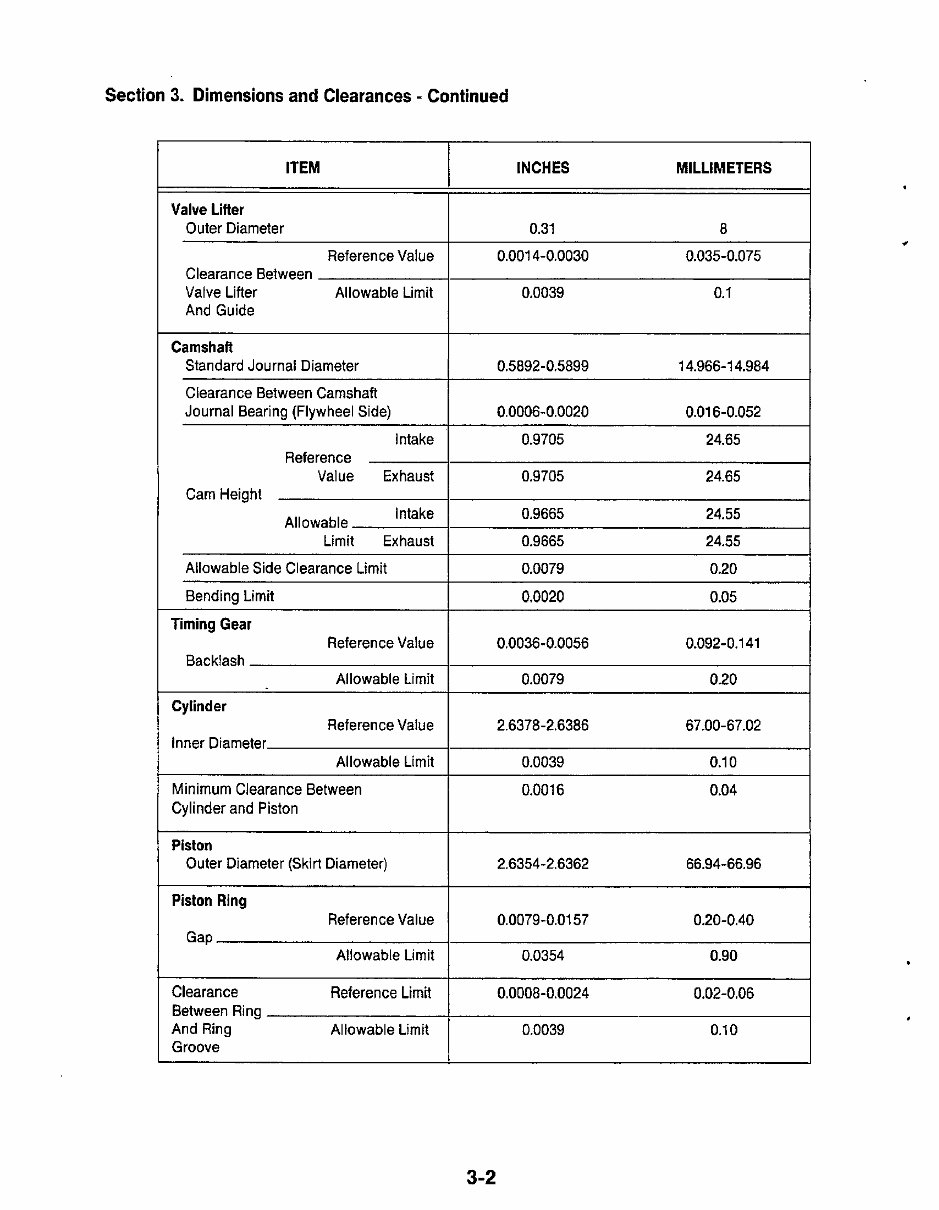
Section 3. Dimensions and Clearances - Continued
ITEM
Valve Lifter
Outer Diameter
ReferenceValue
Clearance Between
Valve Lifter Allowable Limit
And Guide
Camshaft
Standard Journal Diameter
Clearance Between Camshaft
Journal Bearing (Flywheel Side)
Intake
Value Exhaust
Intake
Limit Exhaust
Reference
Cam Height
Allowable
Allowable Side Clearance Limit
Bending Limit
Timing Gear
Backlash
ReferenceValue
Allowable Limit
ReferenceValue
Allowable Limit
Cylinder
Inner Diameter
Minimum Clearance Between
Cylinder and Piston
Piston
Outer Diameter (Skirt Diameter)
Piston Ring
ReferenceValue
Allowable Limit
Gap
Clearance Reference Limit
Between Ring
And Ring Allowable Limit
Groove
INCHES MILLIMETERS
- :
0.001 4-0.0030 0.035-0.075
I
0.0039 0.1
0.5892-0.5899 14.966-1 4.984
0.0006-0.0020 0.01 6-0.052
0.9705 24.65
0.9705 24.65
1
0.9665 24.55
0.9665 24.55
0.0079
0.0020
0.0036-0.0056 0.092-0.1 41
0.0079
2.6378-2.6386 67.00-67.02
0.0039 0.1 0 I
0.001 6 0.04
2.6354-2.6362 66.94-66.96
0.0079-0.01 57 0.20-0.40
0.0354 0.90
I
0.0008-0.0024 0.02-0.06
I
0.0039 0.1 0
.
3-2
You're Reading a Preview
What's Included?
Fast Download Speeds
Online & Offline Access
Access PDF Contents & Bookmarks
Full Search Facility
Print one or all pages of your manual
$41.99
$54.99
Viewed 15 Times Today


Secure transaction
What's Included?
Fast Download Speeds
Online & Offline Access
Access PDF Contents & Bookmarks
Full Search Facility
Print one or all pages of your manual
$41.99
$54.99
- The Onan KV Microlite 2800 Series Generator Complete Workshop Service Repair Manual is a comprehensive resource for servicing and repairing your generator.
- It provides user-friendly step-by-step instructions and illustrations, making every service and repair task effortless.
- This manual is a lifelong asset, allowing you to print specific pages, chapters, or the entire manual, or store it on your tablet or smartphone for easy access.
- Covering all models, engines, trim, and transmission types, this manual ensures you have the necessary information for any specific generator variant.
- It encompasses a comprehensive range of repair procedures, leaving no task unaddressed, and is compatible with all PC and MAC computers, tablets, and mobile phones.
- Adobe Reader is the only software requirement, which is often pre-installed on your computer or can be easily downloaded for free.
- Upon purchase with Visa, MasterCard, or PayPal, the manual will be promptly delivered to the provided email address.
- Empower yourself with the knowledge and guidance needed to maintain and repair your Onan KV Microlite 2800 Series Generator with this comprehensive manual.


