Cummins Onan GGMA GGMB GGMC 1301 Generator Set Complete Workshop Service Repair Manual
What's Included?
Lifetime Access
Fast Download Speeds
Online & Offline Access
Access PDF Contents & Bookmarks
Full Search Facility
Print one or all pages of your manual
Service Manual Generator Set GGMA (Spec A−C) GGMB (Spec A−C) GGMC (Spec A−C) with PowerCommand R 1301 Controller English − Original Instructions 11−2010 A028W933 (Issue 4)
MS-5 iii IMPORTANT SAFETY INSTRUCTIONS SAVE THESE INSTRUCTIONS − This manual contains important instructions that should be followed during installation and maintenance of the generator and batter- ies. Before operating the generator set (genset), read the Operator’s Manual and become familiar with it and the equipment. Safe and efficient operation can be achieved only if the equipment is properly operated and maintained. Many accidents are caused by failure to follow fundamental rules and precautions. The following symbols, found throughout this manual, alert you to potentially dangerous conditions to the op- erator, service personnel, or the equipment. This symbol warns of immediate hazards which will result in severe personal in- jury or death. WARNING This symbol refers to a hazard or un- safe practice which can result in severe per- sonal injury or death. CAUTION This symbol refers to a hazard or un- safe practice which can result in personal injury or product or property damage. FUEL AND FUMES ARE FLAMMABLE Fire, explosion, and personal injury or death can result from improper practices. DO NOT permit any flame, cigarette, pilot light, spark, arcing equipment, or other ignition source near the generator set or fuel tank. Fuel lines must be adequately secured and free of leaks. Fuel connection at the engine should be made with an approved flexible line. Do not use copper piping on flexible lines as copper will be- come brittle if continuously vibrated or repeatedly bent. Natural gas is lighter than air, and will tend to gather under hoods. Propane is heavier than air, and will tend to gather in sumps or low areas. NFPA code re- quires all persons handling propane to be trained and qualified. Be sure all fuel supplies have a positive shutoff valve. Be sure battery area has been well-ventilated prior to servicing near it. Lead-acid batteries emit a highly explosive hydrogen gas that can be ignited by arc- ing, sparking, smoking, etc. EXHAUST GASES ARE DEADLY Provide an adequate exhaust system to properly expel discharged gases away from enclosed or sheltered areas and areas where individuals are likely to congregate. Visually and audibly inspect the exhaust daily for leaks per the maintenance schedule. Make sure that exhaust manifolds are se- cured and not warped. Do not use exhaust gases to heat a compartment. Be sure the unit is well ventilated. Engine exhaust and some of its constituents are known to the state of California to cause cancer, birth defects, and other reproductive harm. MOVING PARTS CAN CAUSE SEVERE PERSONAL INJURY OR DEATH Keep your hands, clothing, and jewelry away from moving parts. Before starting work on the generator set, discon- nect battery charger from its AC source, then dis- connect starting batteries, negative (-) cable first. This will prevent accidental starting. Make sure that fasteners on the generator set are secure. Tighten supports and clamps, keep guards in position over fans, drive belts, etc. Do not wear loose clothing or jewelry in the vicinity of moving parts, or while working on electrical equip- ment. Loose clothing and jewelry can become caught in moving parts. Jewelry can short out elec- trical contacts and cause shock or burning. If adjustment must be made while the unit is run- ning, use extreme caution around hot manifolds, moving parts, etc.
iv ELECTRICAL SHOCK CAN CAUSE SEVERE PERSONAL INJURY OR DEATH Remove electric power before removing protective shields or touching electrical equipment. Use rub- ber insulative mats placed on dry wood platforms over floors that are metal or concrete when around electrical equipment. Do not wear damp clothing (particularly wet shoes) or allow skin surface to be damp when handling electrical equipment. Use extreme caution when working on electrical components. High voltages can cause injury or death. DO NOT tamper with interlocks. Follow all applicable state and local electrical codes. Have all electrical installations performed by a qualified licensed electrician. Tag and lock open switches to avoid accidental closure. DO NOT CONNECT GENERATOR SET DI- RECTLY TO ANY BUILDING ELECTRICAL SYS- TEM. Hazardous voltages can flow from the gen- erator set into the utility line. This creates a potential for electrocution or property damage. Connect only through an approved isolation switch or an ap- proved paralleling device. GENERAL SAFETY PRECAUTIONS Coolants under pressure have a higher boiling point than water. DO NOT open a radiator or heat ex- changer pressure cap while the engine is running. Allow the generator set to cool and bleed the system pressure first. Benzene and lead, found in some gasoline, have been identified by some state and federal agencies as causing cancer or reproductive toxicity. When checking, draining or adding gasoline, take care not to ingest, breathe the fumes, or contact gasoline. Used engine oils have been identified by some state or federal agencies as causing cancer or reproduc- tive toxicity. When checking or changing engine oil, take care not to ingest, breathe the fumes, or con- tact used oil. Keep multi-class ABC fire extinguishers handy. Class A fires involve ordinary combustible materials such as wood and cloth; Class B fires, combustible and flammable liquid fuels and gaseous fuels; Class C fires, live electrical equipment. (ref. NFPA No. 10). Make sure that rags are not left on or near the en- gine. Make sure generator set is mounted in a manner to prevent combustible materials from accumulating under the unit. Remove all unnecessary grease and oil from the unit. Accumulated grease and oil can cause over- heating and engine damage which present a poten- tial fire hazard. Keep the generator set and the surrounding area clean and free from obstructions. Remove any de- bris from the set and keep the floor clean and dry. Do not work on this equipment when mentally or physically fatigued, or after consuming any alcohol or drug that makes the operation of equipment un- safe. Substances in exhaust gases have been identified by some state or federal agencies as causing can- cer or reproductive toxicity. Take care not to breath or ingest or come into contact with exhaust gases. Do not store any flammable liquids, such as fuel, cleaners, oil, etc., near the generator set. A fire or explosion could result. Wear hearing protection when going near an oper- ating generator set. To prevent serious burns, avoid contact with hot metal parts such as radiator, turbo charger and ex- haust system. KEEP THIS MANUAL NEAR THE GENSET FOR EASY REFERENCE
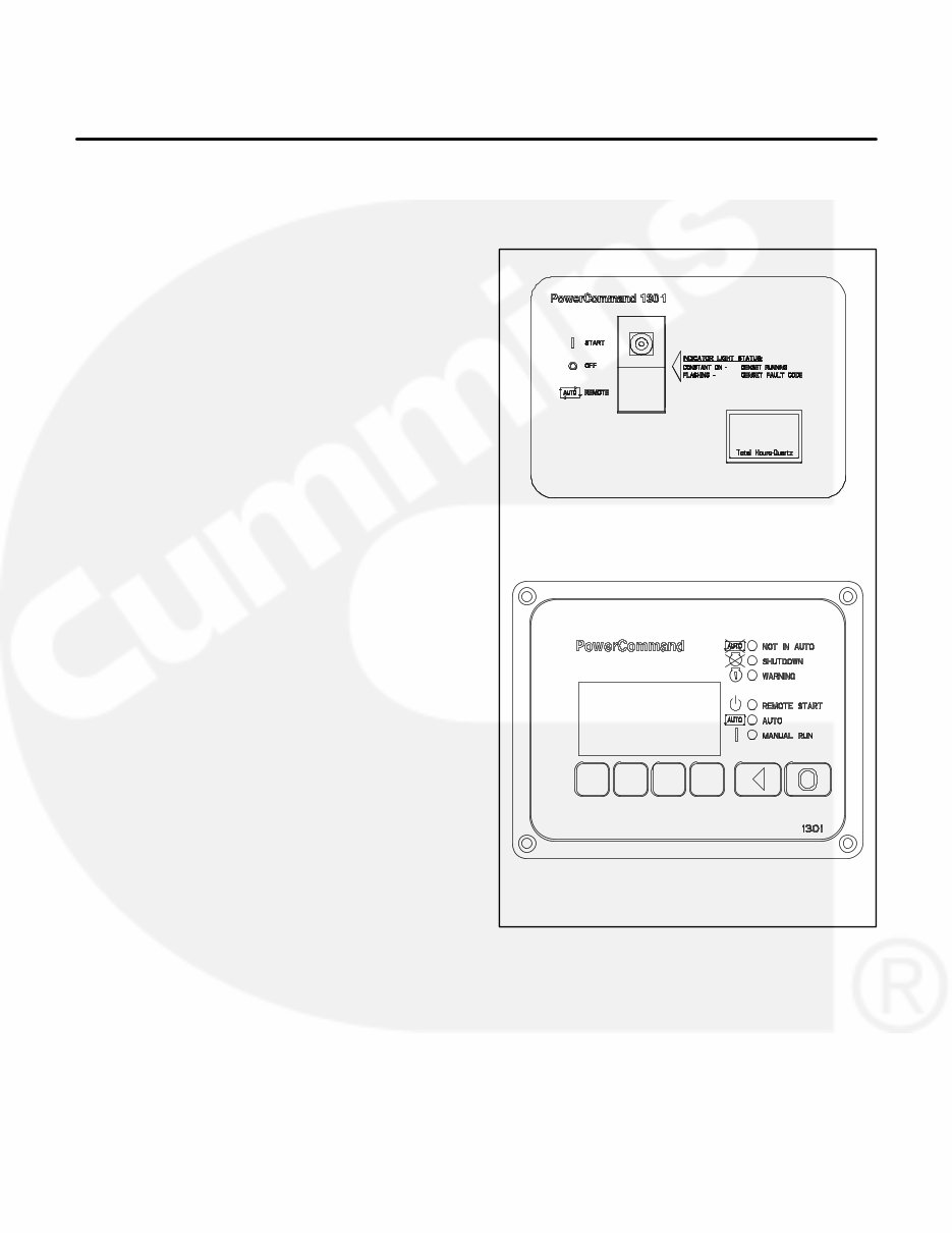
1-1 1. Introduction ABOUT THIS MANUAL This manual provides troubleshooting and repair information regarding the PowerCommand 1301 Control (PCC) and generators for the generator sets (gensets) listed on the front cover. Engine service instructions are in the applicable engine service manual. Operating and maintenance instructions are in the applicable Operator’s Manual. This manual does not have instructions for servicing printed circuit board assemblies. After determining that a printed circuit board assembly is faulty, replace it, do not repair it. Attempts to repair a printed circuit board can lead to costly damage to the equipment. This manual contains basic (generic) wiring diagrams and schematics that are included to help in troubleshooting. Service personnel must use the actual wiring diagram and schematic shipped with each unit. The wiring diagrams and schematics that are maintained with the unit should be updated when modifications are made to the unit. Read Important Safety Instructions and carefully observe all instructions and precautions in this manual. Read the warranty statement provided with the gen- set for US Environmental Protection Agency (EPA) restrictions on servicing specific components. GENERATOR SET CONTROL There are two versions of the PCC 1301 that can be configured with this genset. For reference only, they are referred to as PCC 1301 (Without Display) and PCC 1301 (With Display) in this manual (Figure 1-1). Sections in this manual that are specific to either PCC 1301 control are noted in the section title. All other sections apply to both versions. PCC 1301 (WITHOUT DISPLAY-STANDARD) PCC 1301 (WITH DISPLAY-OPTIONAL) FIGURE 1-1. CONTROL PANEL CONFIGURATIONS
1-2 SYSTEM OVERVIEW The PCC is a microprocessor-based control for Cummins Power Generation generator sets. All generator set control functions are contained on one circuit board (Base board). The Base board provides fuel control, main alternator voltage output regulation and complete generator set control and monitoring. The operating software provides control of the gen- erator set and its performance characteristics, and displays performance information on a digital dis- play panel. It accepts menu-driven control and set- up input from the push button switches on the front panel. TEST EQUIPMENT To perform the test procedures in this manual, the following test equipment must be available True RMS meter for accurate measurement of small AC and DC voltages. Fluke models 87 or 8060A are good choices. Grounding wrist strap to prevent circuit board damage due to electrostatic discharge (ESD). Battery Hydrometer. Jumper Leads. Tachometer or Frequency Meter. Wheatstone Bridge or Digital Ohmmeter. Variac. Load Test Panel. Two guide pins (P/N 420-0625). (Used to aiign drive disc to flywheel.) Megger or Insulation Resistance Meter. InPower Service Tool (PC based genset ser- vice tool). PCC1301 Interface Kit (Used with InPower Service Tool) Distributor seal cap (P/N A026J066) Distributor seal (P/N A028U604) Distributor sealing tool (P/N A028V024) Sealing die stamp (P/N A028V011) Woodward L Series electronic service tool HOW TO OBTAIN SERVICE Always give the complete Model, Specification and Serial number of the generator set as shown on the nameplate when seeking additional service information or replacement parts. The nameplate is located on the back of the control box. WARNING Incorrect service or replacement of parts can result in severe personal injury or death, and/or equipment damage. Service per- sonnel must be trained and experienced to per- form electrical and mechanical service. Read and follow Important Safety Instructions on pages iii and iv.
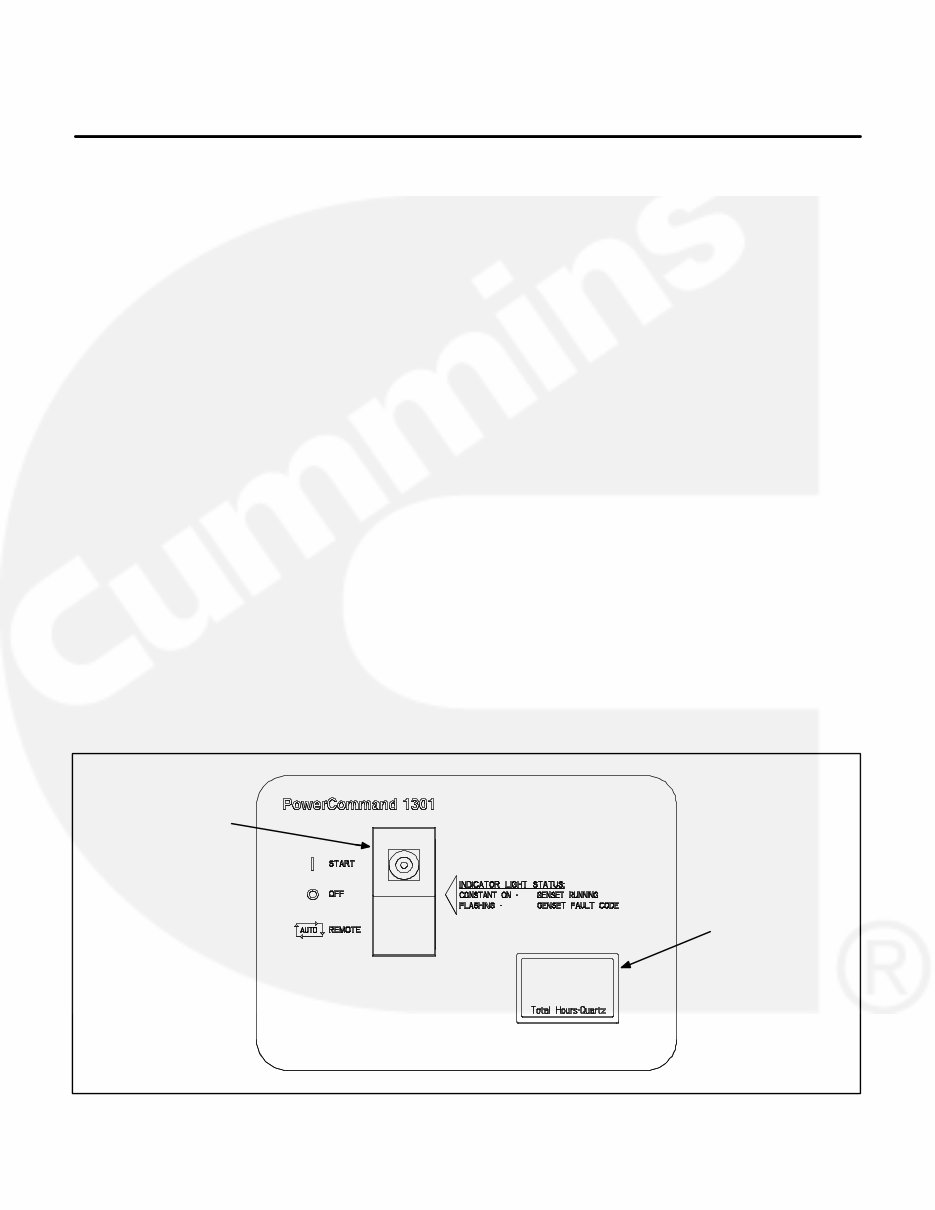
2-1 2. Control Operation (Without Display) GENERAL The following describes the function and operation of the PowerCommand 1301 Control (without dis- play). The switch/indicator and hour meter are lo- cated on the face of the control panel as illustrated in Figure 2-1. CONTROL PANEL Figure 2-1 shows the features of the front panel. It includes one−three position rocker switch to oper- ate the genset and a total hours genset meter. Start/Off/Remote (Auto) Switch This rocker switch is used to select the three operat- ing modes of the genset (Start/Off/Remote). This switch also contains a lamp which is used to indi- cate engine genset running and genset fault codes. OFF Mode: The OFF mode is enabled by moving the control rocker switch to the middle position. The OFF mode will disable the control Auto or Manual modes. If moved to the OFF position during generator set operation (manual or remote start), the engine will immediately shut down. If possible, hot shutdown under load should be avoided to help prolong the reliability of the generator set. The OFF mode is also used to acknowledge shut- down messages after the fault has been corrected. Moving the switch to the OFF position clears the switch fault indication and resets the control. REMOTE (Auto) Mode: The Remote (Auto) mode is enabled by moving the control rocker switch to the bottom position. The Remote mode enables start/stop control of the genset from a remote loca- tion. START Mode: The Start mode is enabled by mov- ing the control rocker switch to the top position. When moved to this position, the control will acti- vate the starting system. Switch Indicator Used to indicate the following genset status: Genset running − constant on Genset fault code − flashing (refer to Section 5 to interpret fault code indicator) Total Hours Meter Displays the total hours of genset operation. HOUR METER THREE POSITION ROCKER SWITCH FIGURE 2-1. FRONT PANEL (WITHOUT DISPLAY)
2-2 THIS PAGE LEFT INTENTIONALLY BLANK
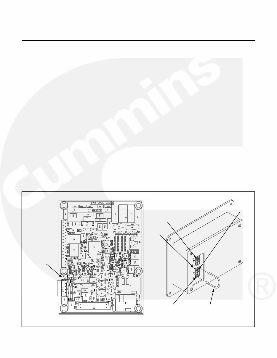
3-1 3. Control Operation (With Display) GENERAL The following describes the function and operation of the PowerCommand 1301 Control (with dis- play). All indicators, control buttons and graphical display are located on the face of the control panel as illustrated in Figure 3-2. CONTROL PANEL POWER ON/OFF MODES The power on/off modes of the control panel and op- erating software are Power On and Sleep. Power On Mode: In this mode, power is continu- ously supplied to the control panel. The control’s operating software and control panel LEDs/graphi- cal display will remain active until the Sleep mode is activated. Sleep Mode: In the Sleep mode, the control’s oper- ating software is inactive and the LEDs and the graphical display on the control panel are all off. Sleep mode is a feature used to reduce battery power consumption when the control is not being used and is in either the Off or Auto mode. When all conditions are met (i.e., no unacknowl- edged faults and the control is in the Off or Auto mode) the Sleep mode is activated after five min- utes of keypad inactivity. To activate the control and view the menu display without starting the generator set, press any control button. When shipped from the factory, Sleep mode is en- abled for both modes (Off and Auto mode). Internal adjustment of the control also allows the Sleep mode to be active only during the Off mode (Base board switch S1) or disabled for both modes (instal- lation of jumper). When disabled, the operating soft- ware will always remain active (Power On mode). S1 switch setting: OFF = Sleep mode is enabled for Auto and Off modes. ON = Sleep mode is enabled for Off mode only. J1/J2 jumper installation: Install jumper between J1-4 and J1-5 to disable sleep mode. (J1 and J2 are identical, either one can be used for jumper.) BASE BOARD J1 J2 J1-5 J1-4 ADD JUMPER TO DISABLE SLEEP MODE FOR AUTO AND OFF MODE S1 SLEEP MODE SELECTION SWITCH FIGURE 3-1. SLEEP MODE ACTIVATION SETTINGS
This complete workshop service repair manual for the Cummins Onan GGMA GGMB GGMC 1301 Generator Set is an invaluable resource for both professional mechanics and DIY enthusiasts.
DESCRIPTION:
This manual provides easy-to-follow, step-by-step instructions and pictures for servicing and repairs, enabling you to save money by performing the work yourself. Once downloaded, the manual is yours to keep forever. You can print out specific pages, chapters, or the entire manual, and it can also be saved to your tablet or smartphone.
MODELS COVERED:
All models, engines, trims, and transmission types are included in this comprehensive manual.
CONTENTS:
This high-quality manual covers all repair procedures from A to Z, ensuring that every repair and service procedure is thoroughly explained.
COMPUTER REQUIREMENTS:
This downloadable manual is compatible with all PC and MAC computers, tablets, and mobile phones. The only software required is Adobe Reader, which is typically pre-installed on most computers or can be downloaded for free.
INSTANT DELIVERY:
Upon payment confirmation via Visa, MasterCard, or PayPal, the manual will be instantly emailed to the address provided during checkout.
Customer satisfaction guaranteed.
Recently Viewed
5,521,897Happy Clients
2,594,462eManuals
1,120,453Trusted Sellers
15Years in Business
Price:
Actual Price:
Cummins Onan GGMA GGMB GGMC 1301 Generator Set Complete Workshop Service Repair Manual