

Onan Service Manual DJBA DJB DJC DJE Diesel Engine
What's Included?
Fast Download Speeds
Online & Offline Access
Access PDF Contents & Bookmarks
Full Search Facility
Print one or all pages of your manual

Caution: This document contains mixed page sizes (8.5 x 11 or 11 x
17), which may affect printing. Please adjust your printer settings
according to the size of each page you wish to print.
4
f
Service
DJBA
DJB
DJC
DJE
Diesel Engines
967-0751
3-88
Printed in USA.
,
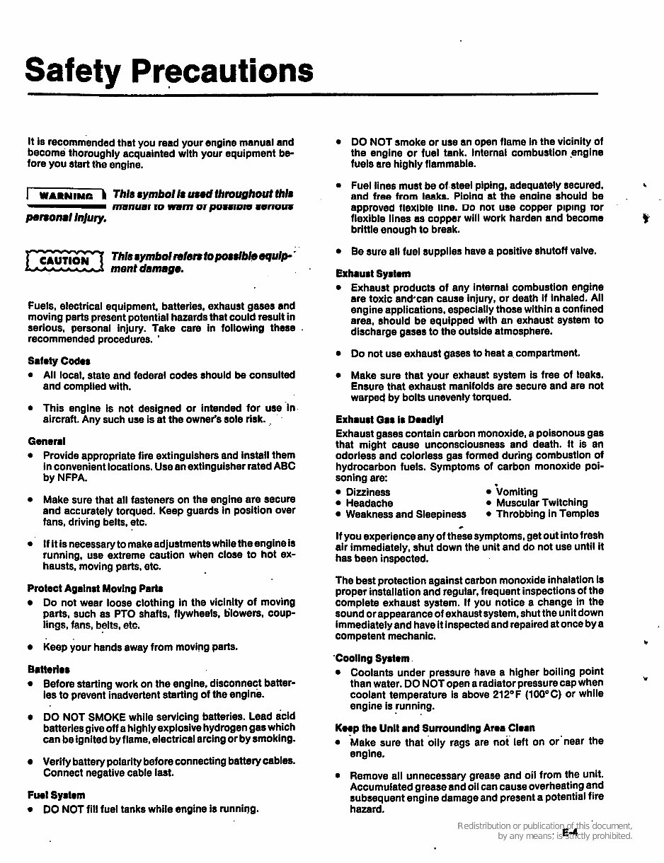
Safety Precautions
It is recommended that you read your engine manual and
become thoroughly acquainted with your equipment be-
fore you start the engine.
Fuels, electrical equipment, batteries, exhaust gases and
moving parts present potential hazards that could result in
serious, personal injury. Take care in following these
recommended procedures. '
S8fOty COdW
0 All local, state and federal codes should be consulted
and complied with.
0 This engine is not designed or intended for use 'in
aircraft. Any such use is at the owner's sole risk. .
'
General
Provide appropriate fire extinguishers and install them
in convenientlocations. Use an extinguisherratedABC
by NFPA.
Make sure that all fasteners on the engine are secure
and accurately torqued. Keep guards in position over
fans, driving belts, etc.
If It is necessary to makeadjustments whiletheengine is
running, use extreme caution when close to hot ex-
hausts, moving parts, etc.
Protect Against Movlng Parts
Do not wear loose clothing in the vicinity of moving
parts, such as PTO shafts, flywheels, tilowers, coup-
lings, fans, belts, etc.
Keep your hands away from moving parts.
Batted08
0 Before starting work on the engine. disconnect batter-
ies to prevent inadvertentstarting of the engine.
DO NOT SMOKE while servicing batteries. Lead acid
batteries give off a highlyexplosivehydrogengas which
can be ignited by flame, electricalarcingor by smoking.
Verify batterypolaritybeforeconnectingbatterycables.
Connect negative cable last.
FwI Systom
0 DO NOT fill fuel tanks while engine is runnirlg.
DO NOT smoke or use an open flame in the vicinity of
the engine or fuel tank. Internal combustion .engine
fuels are highly flammable.
Fuel lines must be of steel piping, adequately secured.
and free from leaks. PiDina at the enaine should be
approved flexible me. PO nor use copper piping ror
flexible lines as copper will work harden and become
brittle enough to break.
Be sure all fuel supplies have a positive shutoff valve.
b
.
E
Exhrust Systom
Exhaust products of any internal combustion engine
are toxic andcan cause injury, or death if inhaled. All
engine applications, especiallythose within a confined
area, should be equipped with an exhaust system to
discharge gases to the outside atmosphere.
Do not use exhaust gases to heat a.compartment.
Make sure that your exhaust system is free of leaks.
Ensure that exhaust manifolds are secure and are not
warped by bolts unevenly torqued.
Exhrust Gas is Dordlyi
Exhaust gases contain carbon monoxide, a poisonous gas
that might cause unconsciousness and death. It is an
odorless and colorless gas formed during combustion of
hydrocarbon fuels. Symptoms of carbon monoxide poi-
soning are:
Dizziness .Vomiting
Headache 0 Muscular Twitching
Weakness and Sleepiness
If you experience any of these symptoms, get out into fresh
air immediately, shut down the unit and do not use until it
has been inspected.
The best protection against carbon monoxide inhalation is
proper installationand regular, frequent inspectionsof the
complete exhaust system. If you notice a change in the
sound or appearance of exhaust system, shut the unit down
immediatelyand have It inspected and repairedat once by a
competent mechanic. b
'Cooling Systom .
0 Coolants under pressure have a higher boiling point
than water. DO NOT open a radiator pressure cap when
coolant temperature is above 212OF (100OC) or while
engine is running.
0 Throbbing in Temples
c
Y
Kwp the Unlt and SurroundingAroa Clem
0
0
'Make sure that oily rags are not left on or'near the
engine.
Remove all unnecessary grease and oil from the unit.
Accumulatedgrease and oil can cause overheatingand
subsequent engine damage and present a potential fire
hazard.
. E4
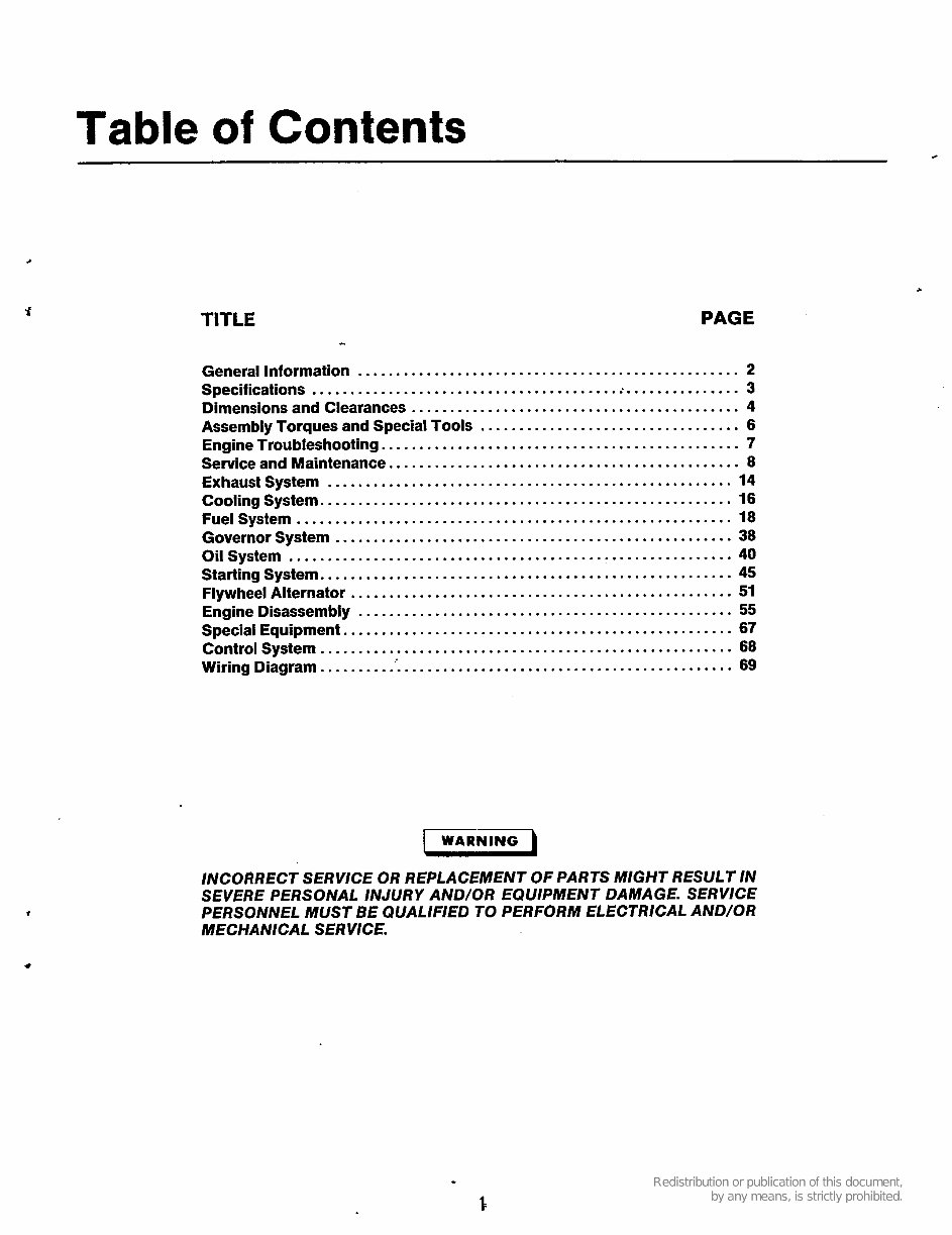
Table of Contents
c
TITLE PAGE
General Information .................................................. 2
Specifications ....................................... ..-. .............. 3
Dimensions and Clearances ........................................... 4
Assembly Torques and Special Tools .................................. 6
Engine Troubleshooting ............................................... 7
Service and Maintenance .............................................. 8
Exhaust System ..................................................... 14
Cooling System ...................................................... 16
Fuel System ......................................................... 18
Governor System .................................................... 38
Oil System .......................................................... 40
Starting System ...................................................... 45
Special Equipment ................................................... 67
Control System ...................................................... 68
Wiring Diagram .......... . ' . ........................................... 69
Flywheel Alternator .................................................. 51
EngineDisassembly ................................................. 55
I WARNING
INCORRECT SERVICE OR REPLACEMENT OF PARTS MIGHT RESULT IN
SEVERE PERSONAL INJURY AND/OR EQUIPMENT DAMAGE . SERVICE
PERSONNEL MUST BE QUALIFIED TO PERFORM ELECTRICAL AND/OR
MECHANlCAL SERVICE .
I
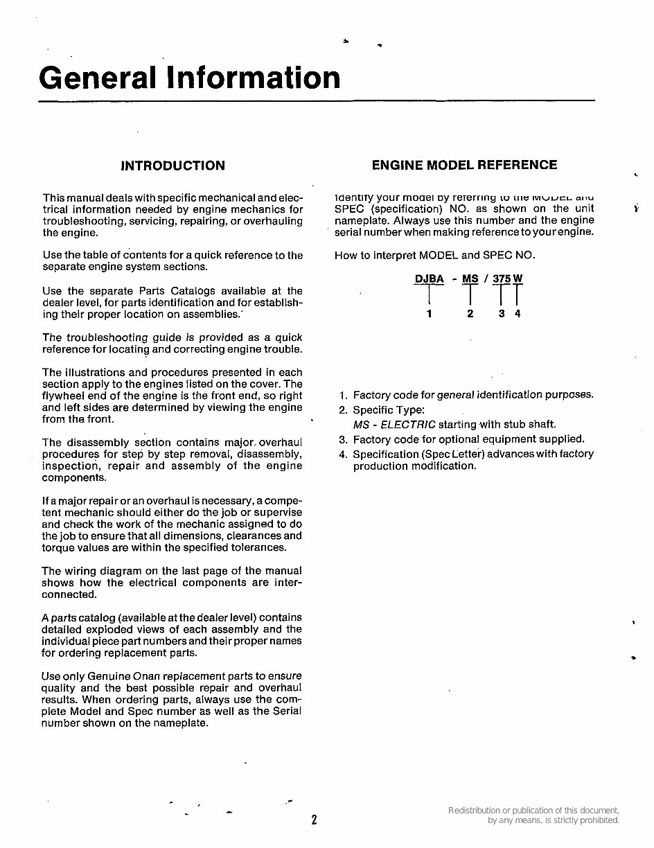
General Information
INTRODUCTION
This manual deals with specific mechanical and elec-
trical information needed by engine mechanics for
troubleshooting, servicing, repairing, or overhauling
the engine.
Use the table of contents for a quick reference to the
separate engine system sections.
Use the separate Parts Catalogs available at the
dealer level, for parts identification and for establish-
ing their proper location on assemblies.'
The troubleshooting guide is provided as a quick
reference for locating and correcting engine trouble.
The illustrations and procedures presented in each
section apply to the engines listed on the cover. The
flywheel end of the engine is the front end, so right
and left sides are determined by viewing the engine
from the front.
The disassembly section contains major,. overhaul
procedures for step by step .removal, disassembly,
inspection, repair and assembly of the engine
components.
If a major repair or an overhaul is necessary, a compe-
tent mechanic should either do the job or supervise
and check the work of the mechanic assigned to do
the job to ensure that all dimensions, clearances and
torque values are within the specified tolerances.
The wiring diagram on the last page of the manual
shows how the electrical components are inter-
connected.
A parts catalog (available at the dealer level) contains
detailed exploded views of each assembly and the
individual piece part numbers and their proper names
for ordering replacement parts.
Use only Genuine Onan replacement parts to ensure
quality and the best possible repair and overhaul
results. When ordering parts, always use the com-
plete Model and Spec number as well as the Serial
number shown on the nameplate.
ENGINE MODEL REFERENCE
c
IUentlTy your moael DY reTerririy LO LII~ IVIWLKL aiiu
nameplate. Always use this number and the engine
serial number when making reference to your engine.
SPEC (specification) NO. as shown on the unit ;
How to interpret MODEL and SPEC NO.
1 2 3 4
1. Factory code for general identification purposes.
2. Specific Type:
3. Factory code for optional equipment supplied.
4. Specification (Spec Letter) advanceswith factory
MS - ELECTRlC starting .with stub shaft.
production modification.
2
Specifications
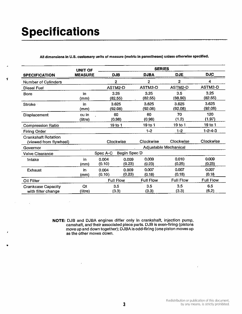
All dimensions in U.S. customary units of measure (metric in parentheses) unless otherwise specified.
UNIT OF SERIES
SPECIFICATION MEASURE DJB DJBA DJE DJC
Number of Cylinders 2 2 2 4
ASTM2-D ASTM2-D ASTM2-D ASTM2- D Diesel Fuel
Bore in 3.25 3.25 3.5 3.25
(mm) (82.55) . (82.55) (88.90) (82.55)
Stroke in 3.625 3.625 3.625 3.625
(mm) (92.08) (92.08) (92.08) (92.08)
Displacement cuin . 60 60 70 120
(litre) (0.98) (0.98) (1-2) (1.97)
Compression Ratio 19 to 1 19 to 1 19 to 1 19 to 1
Firing Order 1-2 1-2 1-2-4-3
Crankshaft Rotation
Governor . Adjustable Mechanical
Valve Clearance Spec A-C Begin Spec D
Clockwise Clockwise Clockwise Clockwise
(viewed from flywheel)
Intake in 0.004 0.009 0.009 0.01 0 0.009
(mm) (0.10) (0.23) (0.23) (0.25) (0.23)
Exhaust in 0.004 0.009 0.007 0.007 0.007
(mm) (0.10) (0.23) (0.18) (0.1 8) (0.1 8
Oil Filter Full Flow Full Flow Full Flow Full Flow
Crankcase Capacity Qt 3.5 3.5 3.5 6.5
with filter change (I i tre) (3.3) (3.3) (3.3) (6.2)
NOTE: DJB and DJBA engines differ only in crankshaft, injection pump,
camshaft, and their associated piece parts. DJB is even-firing (pistons
move up and down together); DJBA is odd-firing (one piston moves up
as the other moves down.
3
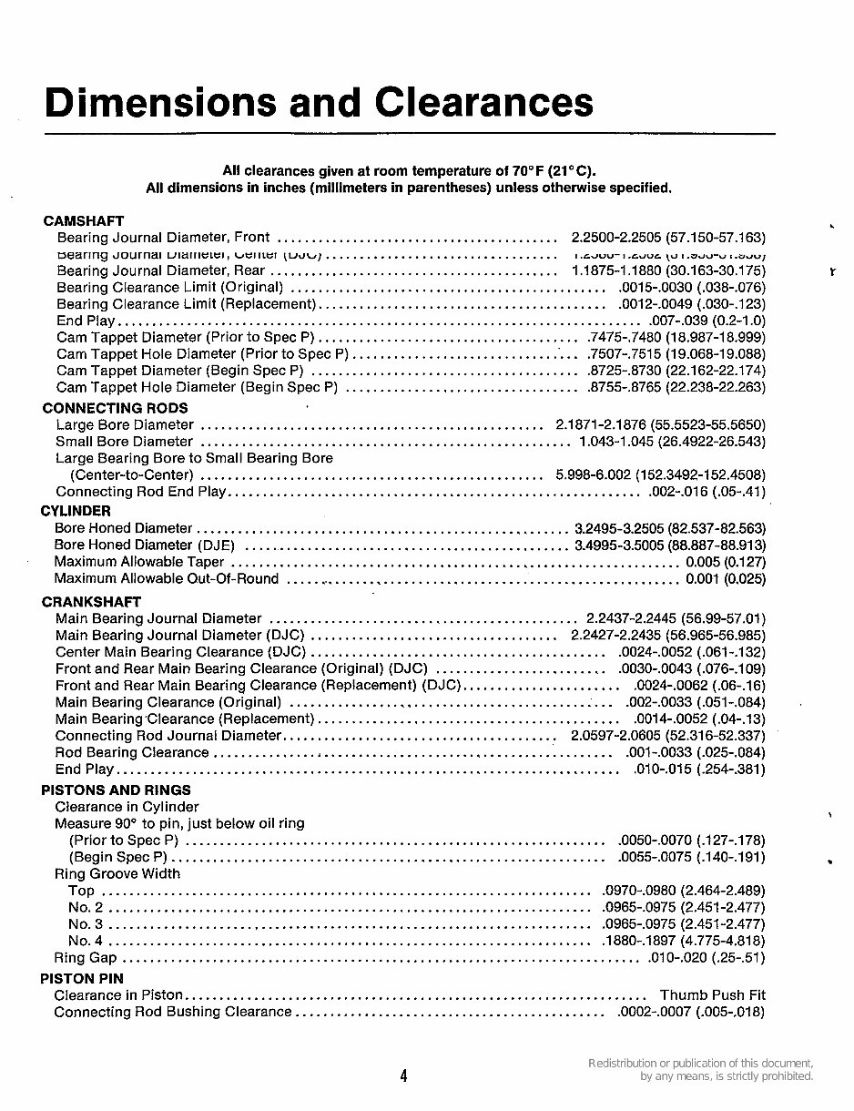
Dimensions and Clearances
All clearances given at room temperature of 70" F (21 O C) .
All dimensions in inches (millimeters in parentheses) unless otherwise specified .
CAMSHAFT
Bearing Journal Diameter. Front ......................................... 2.2500-2.2505 (57.150-57.1 63)
Bearing Journal Diameter. Rear .......................................... 1.1875-1.1880 (30.163-30.175)
Bearing Clearance Limit (Original) .............................................. .0015.. 0030 (.038-.076)
Bearing Clearance Limit (Replacement) .......................................... .0012-.0049 (.030-.123)
End Play ............................................................................ .007-. 039 (0.2-1.0)
Cam Tappet Diameter (Prior to Spec P) ...................................... .7475-. 7480 (18.987-18.999)
Cam Tappet Hole Diameter (Prior to Spec P) .................................. .7507-. 7515 (19.068-19.088)
Cam Tappet Diameter (Begin Spec P) ....................................... .8725.. 8730 (22.162-22.174)
Cam Tappet Hole Diameter (Begin Spec P) .................................. .8755-. 8765 (22.238-22.263)
Large Bore Diameter .................................................. 2.1871-2.1876 (55.5523-55.5650)
Small Bore Diameter ...................................................... 1.043-1.045 (26.4922-26.543)
Large Bearing Bore to Small Bearing Bore
(Center-to-Center) .................................................. 5.998-6.002 (152.3492-152.4508)
Connecting Rod End Play ............................................................ .002-. 016 (.05-.41)
Bore Honed Diameter ...................................................... 3.2495-3.2505 (82.537-82.563)
Bore Honed Diameter (DJE) ............................................... 3.4995-3.5005 (88.887-88.913)
Maximum Allowable Taper ................................................................. 0.005 (0.127)
Maximum Allowable Out-Of-Round .......................................................... 0.001 (0.025)
Main Bearing Journal Diameter ............................................. 2.2437-2.2445 (56.99-57.01)
Main Bearing Journal Diameter (DJC) .................................... 2.2427-2.2435 (56.965-56.985)
Center Main Bearing Clearance (DJC) ........................................... .0024.. 0052 (.061-.132)
Front and Rear Main Bearing Clearance (Original) (DJC) ......................... .0030.. 0043 (.076-.109)
Front and Rear Main Bearing Clearance (Replacement) (DJC) ....................... .0024-.0062 (.06-.16)
Main Bearing Clearance (Original) ............................................ .'. .. .002.. 0033 (.051-.084)
Main Bearing Clearance (Replacement) ............................................ .0014.. 0052 (.04-.13)
Connecting Rod Journal Diameter ........................................ 2.0597-2.0605 (52.316-52.337)
Rod Bearing Clearance .......................................................... .001.. 0033 (.025-.084)
End Play ......................................................................... .010-.015 (.254-.381)
Clearance in Cylinder
Measure 90" to pin. just below oil ring
Bearing Journai uiaiiieiei. ueii~ei \UJ~) .................................. I LJUU- I LJUC [U 1 .a c r ~ - ~ 1 . acruJ
CONNECTING RODS
CYLINDER
CRANKSHAFT
.
PISTONS AND RINGS
(Prior to Spec P) ............................................................. .0050.. 0070 (.127-.178)
(Begin Spec P) ............................................................... .0055-. 0075 (.140-.191)
Ring Groove Width
TOP ....................................................................... .0970-. 0980 (2.464-2.489)
No.2 ...................................................................... -0965-.0975 (2.451-2.477)
No . 3 ...................................................................... .0965.. 0975 (2.451-2.477)
NO . 4 ...................................................................... .1880.. 1897 (4.775-4.818)
Ring Gap ........................................................................... .010-. 020 (.25-51)
Clearance in Piston ................................................................... Thumb Push Fit
Connecting Rod Bushing Clearance ............................................. -0002-.0007 (-005-.018)
PISTON PIN
4
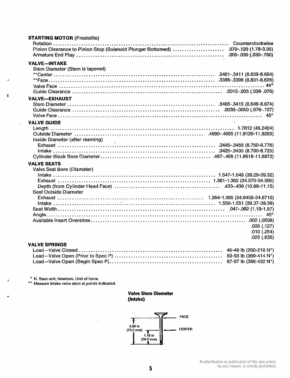
STARTING MOTOR (Prestolite)
Rotation ........................................................................... Counterclockwise
Pinion Clearance to Pinion Stop (Solenoid Plunger Bottomed) . .... . . ...... ... . .... . -070--120 (1 -78-3.05)
Armature End Play . ..... . .. ... . . .. . . . .... . .. . .. . . . . .. . .. . . . . ... . . ... . . ... . . ...... .005--030 (-030-.760)
Stem Diameter (Stem is tapered)
**Center .... ... . . . . .. ... . . . . .. . ..... . . . .. ... . . . .... . . . . ..... . . . . . . . . . . .. . .... -3401 -.3411 (8.639-8.664)
**Face ....... .. ... .. .. . . . . . .. . .. . . . . . .. . . . .. . . . ... .. .. . . . . . . . . . . . . . . . ... .. .. . .3386--3396 (8.601-8.626)
Valve Face ....................................................................................... 44'
Guide Clearance .. . .. . .. .. .. ..... . ... . .. . .. . . . . . . . . . . . .. . . . .. . .. ... .. ... .. . .. .. . .0015-.003 (-038-.076)
Stem Diameter . ... ... . . . . . .. ..... . ... . .. . . ... . .. ..... ........ ..... . .. . . .. . ... -3405--3415 (8.649-8.674)
Guide Clearance . . . ..... . . .. .. . . .. .. . . . .. .... . ......... . . . ... ..... .. . . ... . ..... .0030-.0050 (.076-.127)
Valve Face ....................................................................................... 45"
Length .............................................................................. 1.7812(45.2424)
Outside Diameter ....... . . .. . ... . .. ... . ...... . . . .... . . .... . .. ...... . .... .4690-.4695 (1 1.9126-1 1.9253)
Inside Diameter (after reaming)
Exhaust . . . . . .. . .. .. . . . ...... . ........ . .... . . . . ... . . . . .. . . . ...... .. .. . ..... .3445-.3455 (8.750-8.776)
Intake ..................................................................... .3425-.3435 (8.700-8.725)
Cylinder Block Bore Diameter.. ... ... . ... . .... . . . .... . . .. . . . . . . . .... . . ... . . . .467-.468 (11.8618-1 1.8872)
Valve Seat Bore (Diameter)
VALVE-INTAKE
t
VALVE-EXHAUST
. VALVEGUIDE
VALVE SEATS
Intake .... . ... . . . . .. . ... .... . .. . .. . ..... . . . . . . ...... . . .. . . . .. . . . . . . ... . ... . 1.547-1 548 (39.29-39.32)
Exhaust . ...... .. . .. ............ . .......... . . . ...... .. .. . . .. . . . ... . , .. . . . 1.361-1.362 (34.570-34.595)
Depth (from Cylinder Head Face) .. . . . ... . .. . . . ... ... . . . . . . .. .... . .. . . . . . .. .. . .433-.439 (10.99-1 1.15)
Exhaust .. . ... .. . . . .... . .... . .. . .... . ..... . .. .. . ... .... . . ........ . . .. 1.364-1.365 (34.6456-34.6710)
Intake .... . . .. .. . . ... . .. .. .. . . . . .. :'. . ......... . . ... .. . .. . . .... . . . .. . .... ... 1 S50-1.551(39.37-39.39)
Seatwidth ....................................................................... .047-.062 (1.19-1.57)
Angle.. . . . ............... . ... .... . .. . ........ . . . .. .. . . ... . . ... . ..... . . . ...... . . .. . . . . . . . .... . .. 45"
Available Insert Oversizes .. . ... . .. . .. . . . . . . .. ...... . ... . .... . . . . . . . . .. . ........ .. . .. . . . .... .002(.0508)
.005 (.127)
.010(.254)
.025(.635)
Load-Valve Closed . ... .. . .. . .. . ............... . .. . ... . . . . . . ............... . .. . . 45-49 Ib (200-218 N*)
Load-Valve Open (Prior to Spec P) . .... . .. . ... . . .. . ... . . . . . . . . . ..... .. ... . .... . . 83-93 Ib '(369-414 N*)
Load-Valve Open (Begin Spec P). ............ . . . .. .. .... .... . . . . ..... ..... . . . . .. 87-97 Ib (388-432 N*)
Seat Outside Diameter
VALVE SPRINGS
4
* N. Base unit, Newtons. Unit of force.
** Measure intake valve stem at points indicated.
*
Valve Stem Diameter
(Intake)
2.96 in
1.18 in
5
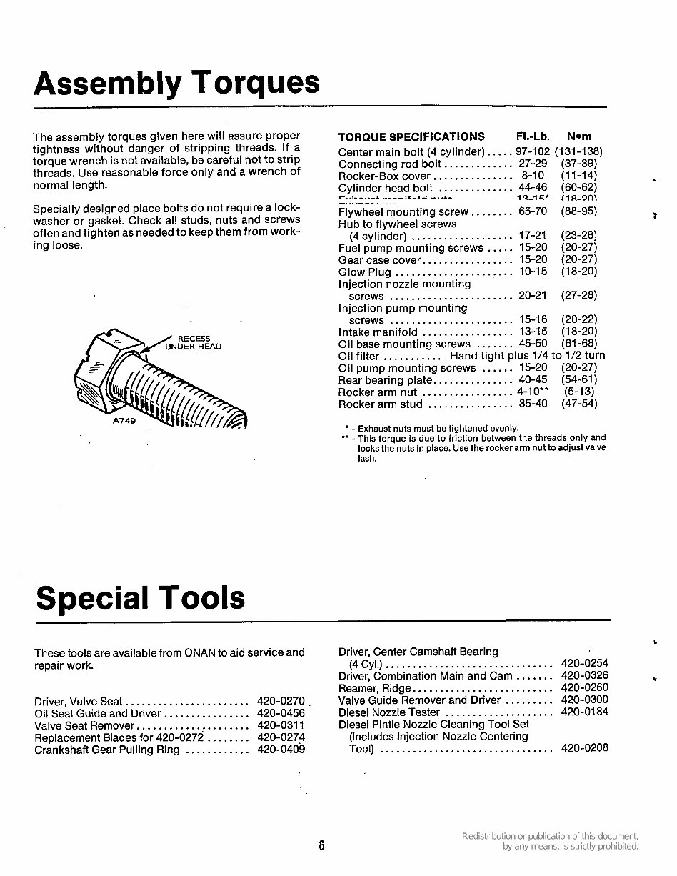
Assembly Torques
The assembly torques given here will assure proper
tightness without danger of stripping threads. If a
torque wrench is not available, be careful not to strip
threads. Use reasonable force only and a wrench of
normal length.
Specially designed place bolts do not require a lock-
washer or gasket. Check all studs, nuts and screws
often and tighten as needed to keep them from work-
ing loose.
Special Tools
TORQUE SPECIFICATIONS Ft.-Lb. Nom
Center main bolt (4 cylinder). . .. . 97-102 (131-138)
Connecting rod bolt., . .......... 27-29
Rocker-Box cover.. . . . . .. . .. . . .. 8-10
Cylinder head bolt . . . . . . . , .. .... 44-46
Flywheel mounting screw.. ..... . 65-70
Hub to flywheel screws
(4 cylinder) .. .. . . , . . . .. . .. . . . . 17-21
Fuel pump mounting screws . . . . . 15-20
Gear case cover.. . . ... . .... . . . . . 15-20
Injection nozzle mounting
screws .... . . . . . .... . ..... . . .. 20-21
Injection pump mounting
screws ... . . . . ... . . . . . . ....... 15-16
Intake manifold . . . . . . . . . ... . .... 13-15
Oil base mounting screws . . . . . . . 45-50
Oil filter . . . . . . ... . . Hand tight plus 1/4 to 1/2 turn
Oil pump mounting screws ...... 15-20
Rear bearing plate.. . . . . ... . . . . . . 40-45
Rocker arm nut . . . . . . ........... 4-IO**
Rocker arm stud . . . . . . . .... ... . . 35-40
(37-39)
(11-14)
(60-62)
(88-95)
(23-28)
(20-27)
(20-27)
(27-28)
(20-22)
(18-20)
(61-68)
(20-27)
(54-61)
(5-13)
(47-54)
1 Q-I r;* 1.1 R-3l-l\
n-. -1- -_.-A -- -.-:.C-i A -. . & , .
-. . . . -. -. - - . .. -.
Glow Plug ... . . . .. . . . . . . ........ 10-15 (18-20)
- Exhaust nuts must be tightened evenly.
** - This torque is due to friction between the threads only and
locks the nuts in place. Use the rocker arm nut to adjust valve
lash.
h
These tools are available from ONAN to aid service and Driver, Center Camshaft Bearing
Driver, Combination Main and Cam ....... 420-0326
Reamer, Ridge. . .. . .. . . .. .. ..... . ....... 420-0260
Valve Guide Remover and Driver . . . ... . . . 420-0300
Diesel Nozzle Tester . . .... . . ............ 420-0184
Diesel Pintle Nozzle Cleaning Tool Set
(Includes Injection Nozzle Centering
repair work. (4 Cyl.) . ... . ..... . ...... . . . .. . . . . . . ... 420-0254
*
Driver, Valve Seat . ....... . .. . . . . . . ... .. . 420-0270 .
Oil Seal Guide and Driver.. .. . . ... ...... . 420-0456
Valve Seat Remover. . . ... . .. . ... . . . .. . .. 420-031 1
Replacement Blades for 420-0272 . .. .. . . . 420-0274
Crankshaft Gear Pulling Ring . ... .... . . . . 420-0409 Tool) .... .... ..... . ... . .. . . . .. ... . . . . 420-0208
6
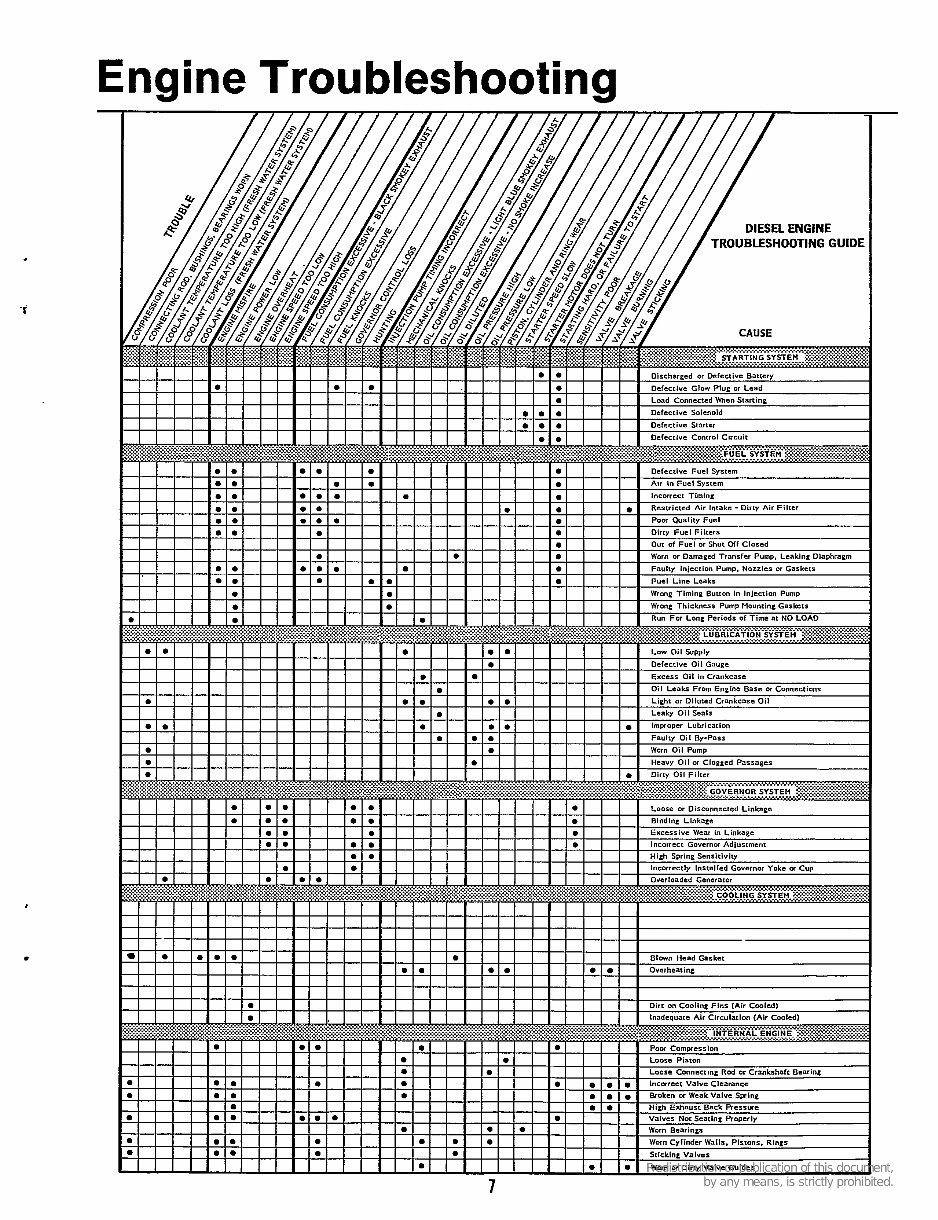
Engine Troubleshooting
You're Reading a Preview
What's Included?
Fast Download Speeds
Online & Offline Access
Access PDF Contents & Bookmarks
Full Search Facility
Print one or all pages of your manual
$52.99
Viewed 19 Times Today


Secure transaction
What's Included?
Fast Download Speeds
Online & Offline Access
Access PDF Contents & Bookmarks
Full Search Facility
Print one or all pages of your manual
$52.99
If you own or need to work on any of these engines, this is the service manual for you. It covers in great detail all the information you need, including:
- General Information
- Specifications
- Dimensions and Clearances
- Assembly Torques and Special Tools
- Engine Troubleshooting
- Service and Maintenance
- Exhaust System
- Cooling System
- Fuel System
- Governor System
- Oil System
- Starting System
- Special Equipment
- Control System
- Wiring Diagram
- Flywheel Alternator
- Engine Disassembly
This workshop service repair manual is fully bookmarked, allowing you to quickly navigate to the section you need.


