

Onan CCK industrial engine parts manual
What's Included?
Fast Download Speeds
Online & Offline Access
Access PDF Contents & Bookmarks
Full Search Facility
Print one or all pages of your manual

The following catalog
has gaps in its page
numbers, or doesn’t
have any numbers.
We have chosen to
leave the page
numbering in the
order that Acrobat
assigns it.
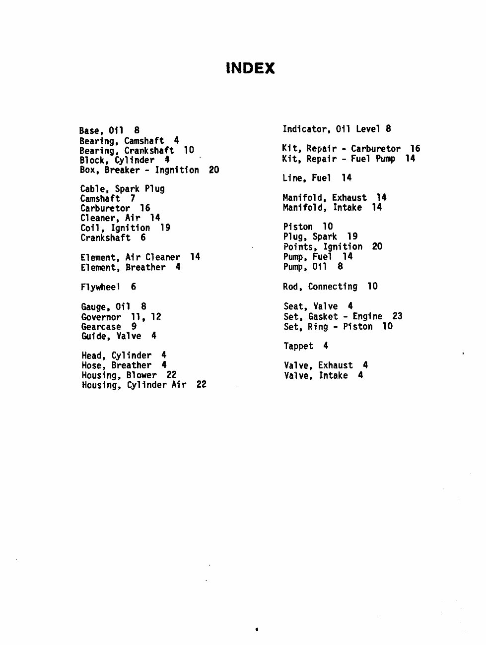
INDEX
Base, Oil 8
Bearing, Camshaft 4
Bearing, Crankshaft 10
Block, Cylinder 4 “
Box$ BFeaker - Ingnition 20
Cable, Spark Plug
Camshaft 7
Carburetor 16
Cleaner, Air 14
Coil, Ignition 19
Crankshaft 6
Element, Air Cleaner 14
Element, Breather 4
Flywheel 6
Gauge, Oil 8
Governor 11, 12
Gearcase 9
Guide, Valve 4
Head, Cylinder 4
Hose, Breather 4
Housing, Blower 22
Housing, Cylinder Air 22
Indicator,Oil Level 8
Kit, Repair - Carburetor 16
Kit, Repair - Fuel Pump 14
Line, Fuel 14
Manifold, Exhaust 14
Manifold, Intake 14
Piston 10
Plug, Spark 19
Points, Ignition 20
Pump, Fuel 14
Pump, Oil 8
Rod, Connecting 10
Seat, Valve 4
Set, Gasket - Engine 23
Set, Ring - Piston 10
Tappet 4
Valve, Exhaust 4
Valve, Intake 4
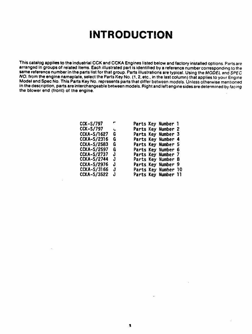
This catalog applies to the industrial CCK and CCKA Engines listed below and factory installed options. Parts are
arranged in groups of related items. Each illustrated part is identified by a reference number corresponding to the
same reference number in the parts list for that group. Parts illustrations are typical. Using the MODEL and SPEC
NO. from the engine nameplate, select the Parts Key No. (1, 2, etc., in the last column) that applies to your Engine
Model and Spec No. This Parts Key No. represents piwts that differ IF--=
=,-=? I model% ‘u’#ass otherwise mentioned
in the description, parts are interchangeable between models. Right and left engine sides are determined by lacing
the Mowr end (front) of the engine.
CCK-S/797
CCK-S/797
CCKA-S/l627
CCKA-S/2316
CCKA-S/2583
CCKA-S/2597
CCKA-S/2737
CCKA-S/2744
CCKA-S/2976
CCKA-S/3166
CCKA-S/3522
3
Parts Key Number 1
Parts Key Number 2
Parts Key Number 3
Parts Key Number 4
Parts Key Number 5
Parts Key Number 6
Parts Key Number 7
Parts Key Number 8
Parts Key Number 9
Parts Key Number 10
Parts Key Number 11
SQA Al
2
REF. PART QTY.
woe MO* USED
.. —.-.
PART
DESCRIPTION
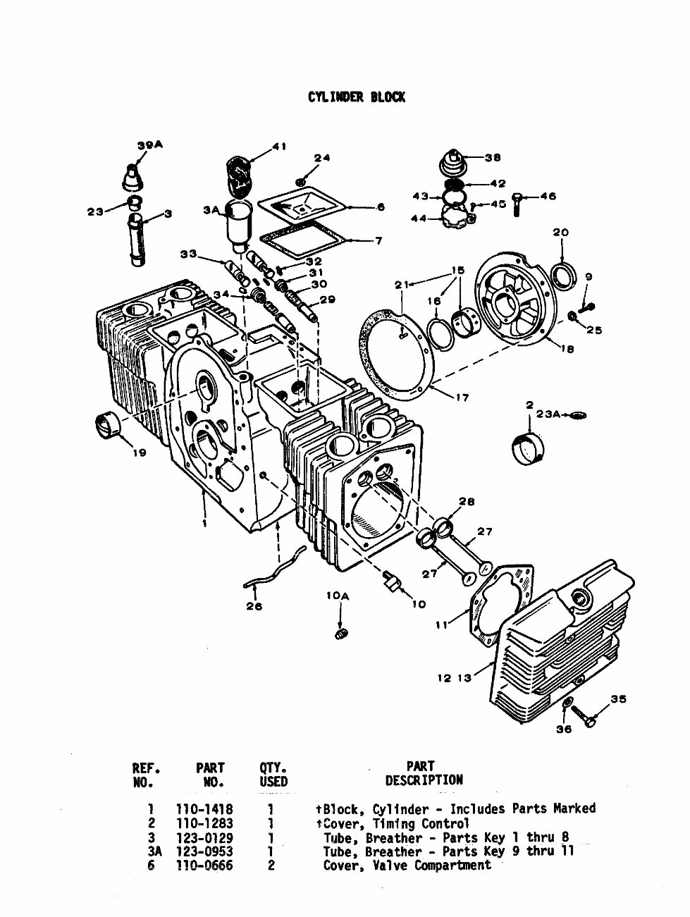
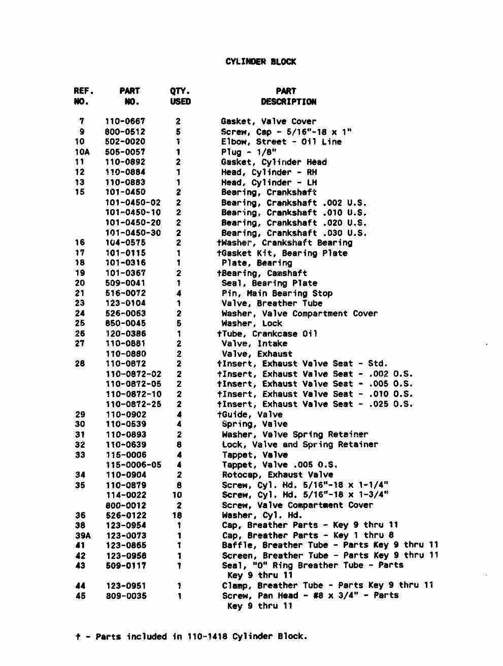
1 110-1418 1 tBlock, Cylinder - Includes
2 110-1283 1 $Cover, Timing Control
3 123-0129 1 Tube, Breather - Parts Key
3A 123-0953 1 Tube, Breather - Parts Key
6 110-0666 2 Cover, Valve Compartment
Parts Marked
1 thru~
9thru 11 “-
REF.
MO.
7
9
10
10A
11
12
13
15
16
17
Is
19
20
21
23
24
25
26
2?
28
29
30
31
32
33
34
35
36
30
39A
41
42
43
44
45
PART
m.
110-0667
800-0512
502-0020
505”0057
110-0892
~~o-~fJ84
110-0883
101-04s0
101-0450-02
101-0450-10
101-0450-20
101-0450”30
104”0575
101-0115
101-0316
101-0367
509-0041
516-0072
123-0104
526-0063
850-0045
120-0386
110-0881
110-0880
110-0872
110-0872-02
110-0872-05
110-0872-10
110-0872-25
110-0902
110-0539
110-0893
110-0639
115-0006
115-0006-05
110-0904
110-0879
114-0022
800-0012
526-0122
123-0954
123-0073
123-0865
123-0958
509-0117
123-0951
809-0035
QTY.
2
5
1
1
2
1
1
2
2
2
2
2
2
1
1
2
1
4
1
2
5
1
2
2
2
2
2
2
2
4
4
2
8
4
4
2
8
10
2
1$
1
1
1
1
1
1
1
PAR?
DESCRIPTION
Gasket, Valve Cover
Screw, Cap - 5/16’’-18 X 1“
Elbow, SWvmt - Oil L.fne
Plug - 1/8”
Gasket, Cylinder Head
Head, Cylinder - RH
Head, Cylinder - LH
Bearing, Crankshaft
Bearing, Crankshaft .002 U.S.
Bearing, Crankshaft .010 U.S.
Bearing, Crankshaft .020 U.S.
Bearing, Crankshaft .030 U.S.
tWasher, Crankshaft Bearing
tGasket Kit, Bearing Plate
Plate, Bearing
tBearing, Camshaft
Seal, Bearing Plate
Pin, Main Bearing Stop
Valve, Breather Tube
Washer, Valve Compartment Cover
Washer, Lock
tTube, Crankcase Oil
Valve, Intake
Valve, Exhaust
tInsert, Exhaust Valve Seat - Std.
?Insert, Exhaust Valve Seat - .002 0.S.
tInsert, Exhaust Valve Seat - .005 0.S.
tInsert, Exhaust Valve Seat - .010 0.S.
t~nsert, Exhaust Valve Seat - .025 0.S.
tGuide, Valve
Spring, Valve
Washer, Valve Spring l?eta~ner
Lock, Valve and Spring Retainer
Tappet, Valve
Tappet, Valve ,005 0,S.
f?otocap, Exhaust Valve
Screw, Cyl. lid. 5/16’’-18 X 1-1/4”
Screw, Cyl. Hd. 5/16’’-18 x 1-3/4”
Screw, Valve Compartment Cover
Washer, Cyl. Hd.
Cap, Breather Parts - Key 9 thru 11
Cap, Breather Parts - Key 1 thru 8
Baffle, Breather Tube - Parts Key 9 thru 11
Screen, Breather Tube - Parts Key 9 thru 11
Seal, “O” Ring Breather Tube - Parts
Key 9 thru 11
Clamp, Breather Tube - Parts Key 9 thru 11
Screw, Pan Head - #8 x 3/4” - Parts
Key 9 thru 11
?- Parts included in 110--1418 Cylinder Block.
REF.
NO.
1
2
3
4
5
8
9
10
11
16
17
18
4
PART
NO.
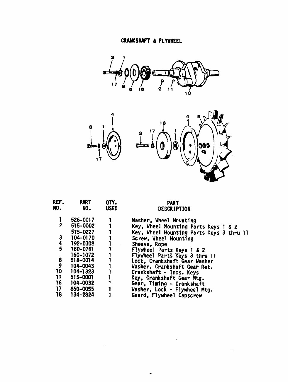
526-0017
515-0002
515-0227
104-0170
192-0308
160-0761
q-60+J72
518-0014
104-0043
;;:-;::;
104~0032
850-0055
134-2824
QTY.
USED
PART
DESCRIPTION
Washer, Wheel Mounting
Key, Mheel Mounting Parts Keys 1 & 2
Key, Wheel Mounting Parts Keys 3 thru 11
Screw, Wheel Mounting
SF@a~e$Rope
Fl=wheel Parts Keys 1 & 2
Flywheel Parts !(eys3 thru 11
Lock, CrankshaftGear Washer
Washer, CrankshaftGear Ret.
Crankshaft - Incs. Keys
Key, CrankshaftGear Mtg.
fiear,Timing - Crankshaft
Washer, Lock - FlywheelMtg.
Guard, Flywheel Capscrew
REF.
No.
1
2
3
4
5
6
7
;
::
12
13
Jg
15
16
17
18
PART
m.
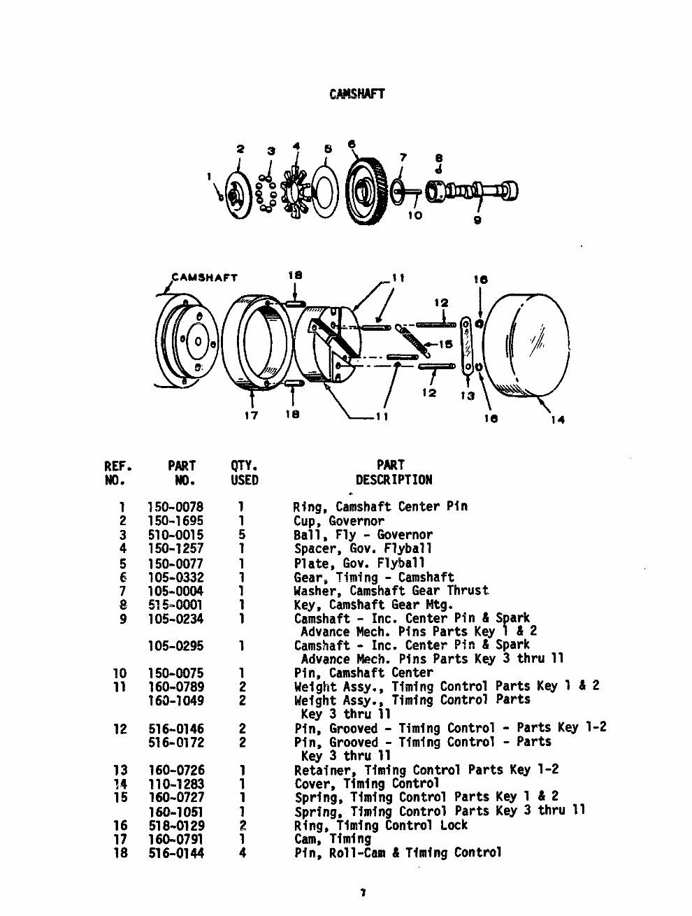
150-0078
150-1695
510-0015
150-1257
150-0077
105-C?332
105-0004
~ ml
?05-0234
105-0295
150-0075
160-0789
160-1049
516-0146
516-0172
160-0726
110-1283
160-0727
160-1051
518-0129
160-0791
516-U 44
17
QTY.
USED
1
1
5
1
1
1
1
1
1
1
1
2
2
2
2
1
1
1
1
2
1
4
PART’
DESCRIPTION
.
Ring, Camshaft Center
Cup, Governor
Ball, Fly - Governor
Spacer, Gov. Flyball
Plate, Gov. Flyball
le
“14
PIn
Gear,-Timing--Camshaft
!iasher,CamshaftGear Thrust
Key, Camshaft Gear Mtg.
Camshaft - Inc. Center Pin & Spark
Advance hlech,Pins Parts Key 1 ii2
Camshaft- Inc. Center Pin & Spark
Advance Mech. Pins Parts Key 3 thru 11
Pin, Camshaft Center
Weight Assy., Timing Control Parts Key 1 & 2
Weight Assy., Timing Control Parts
Key 3 thru 11
Pin, Grooved - Timing Control o parts Key 1-2
Pin, Grooved -Timing Control - Parts
Key3 thru 11
Retatner, Timing Control Parts Key 1-2
Cover, Timing Control
Spring, Timing Control Parts Key 1 &2
Spring, Timing Control Parts Key3 thru 11
Ring, Timing Control Lock
Cam, Timing
Ptn, Roll-Cam & Timing Control
7
n
OIL BASE 8 OIL PW
I 4*
w
17
~~F.
●
1
2
3
4
5
7
8
9
10
11
12
13
14
15
16
17
18
19
25
26
27
28
29
PART
NO.
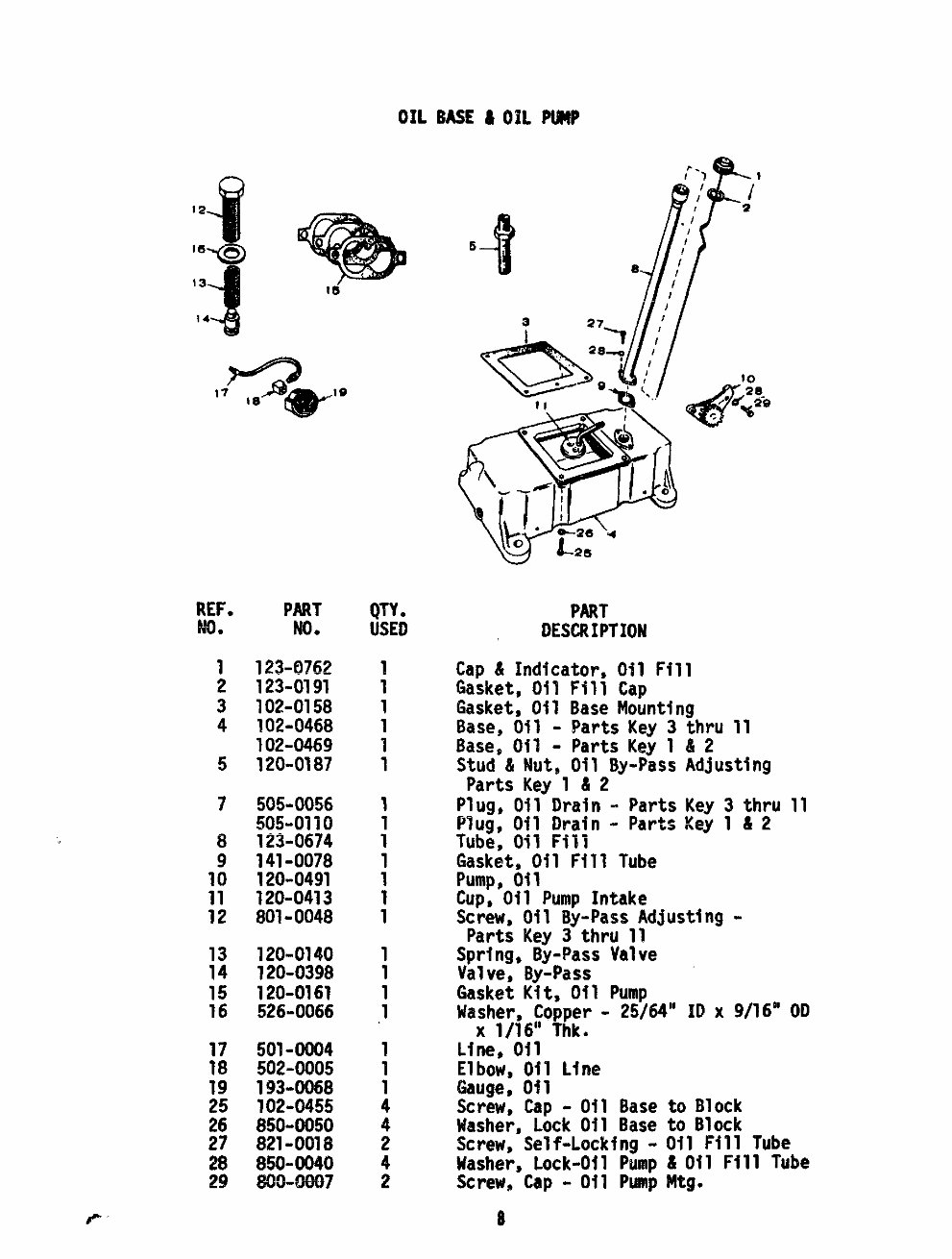
123-0762
123-0191
102-0158
102-0468
102-0469
120-0187
505-0056
505-01iO
i23-0674
;;$;:;;
120~0413
801-0048
120-0140
120-0398
120-0161
526-0066
501-0004
502-0005
;;:-::;:
:3;:;:;:
850=0040
800-0007
QTY.
USED
1
1
:
1
1
1
i
1
1
1
1
1
1
1
1
.1
1
1
1
4
4
2
4
2
5
-t
A
27-1
PART
DESCRIPTION
Cap & Indicator,Oil Fill
Gasket, Oil Fill Cap
Gasket, Oil Base Mounting
Base, Gil - Parts Key 3
Base, Oil - Parts Key 1
Stud & Nut, Oil BY+SS
Parts Key 1 & 2
Plug, Oil Drain - Parts
Plug, Oil Drain - Parts
Tube, Oil Ffll
Gasket, Oil Fill Tube
Pump, oil
~hru 11
82
Adjusting
Key 3 thru 11
Key 1 & 2
Cup;”Oil Pump Intake
Screw, Oil By==PassAdjusting-
Parts Key 3 thru 11
Spring, By-Pass Valve
Valve, By-Pass
Gasket Kit, Oil Pump
Washer, Copper - 25/64” ID X 9/16” OD
X 1/16” Thk.
Line, Oil
Elbow, Oil Line
Gauge, Oil
Screw, Cap -Oil Base to Block
Washer, Lock Oil Base to Block
Screw, Self-Locking- Oil Fill Tube
Masher, Lock-Oil Pump &Oil Fill Tube
Screw, Cap - Oi1 Pump Mtg.
8
REF. PART
NO* No.
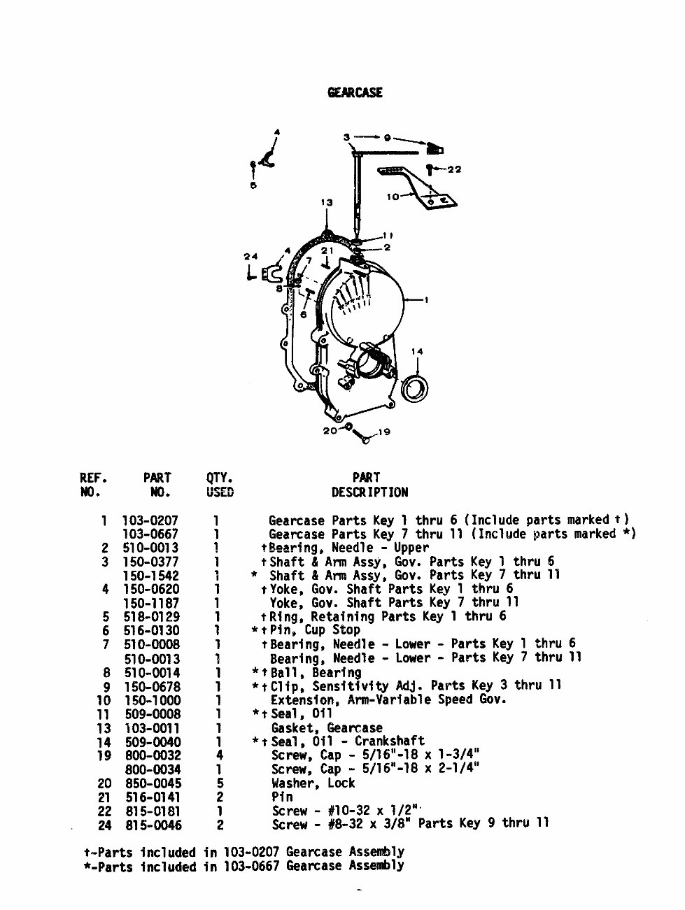
1 103-0207
103-0667
2 510-0013
3 150-0377
150-1542
4 150=-0620
150-1187
5 518-0129
6 516-0130
7 510-0008
510-0013
8 510-0(914
9 150-0678
10 150-1000
11 509-0008
13 103-0011
14 509-0040
19 800-0032
800-0034
20 850-0045
21 516-0141
22 815-0181
24 815-0046
4
4!
3 -—a~
r
b
T
p22
s
13
\
10
;e.
I
24
L
1
1
~
1
7
1
1
1
1
1
1
1
1
1
1
1
1
4
1
5
2
1 Screw - #1O-32 x 1/2””
2 Screw - #8-32 x 3/8”
PART
DESCRIPTION
Gearcase Parts Key 1 thru 6 (Include parts marked ~)
Gear’case Parts Key 7 thru 11 (Include parts marked *)
t~earlngg Needle - Upper
tShaft & Arm Assy, Gov. Parts Key 1 thru 6
* Shaft & Arm Assy, Gov. Parts Key 7 thru 11
tYoke, Gov. Shaft Parts Key 1 thru 6
Yoke, Gov. Shaft Parts Key 7 t!m! 11
tRing, Retaining Parts Key 1 thru 6
*tPine Cup Stop
tBearing, Needle - Lower - Parts Key 1 thru 6
Bearing, Needle - Lower - parts Key 7 thru 11
*tBall, Bearing
*tC~iP, Sensitivity Adj. parts Key 3 thru 11
Extension, Arm-variable Speed Gov.
*tSeal~ Oil
Gasket, Gearcase
*tSeal, Oil - Crankshaft
Screw, Cap - 5/16“-18 x 1-3/4”
Screw, Cap - 5/16“-18 x 2-1/4”
Masher, Lock
Pin
t-Parts included in 103-0207 GearCase Assembly
Parts Key 9 thru 11
*-Parts inc~uded in 103-0667 GearCase Assembly
You're Reading a Preview
What's Included?
Fast Download Speeds
Online & Offline Access
Access PDF Contents & Bookmarks
Full Search Facility
Print one or all pages of your manual
$30.99
Viewed 92 Times Today


Secure transaction
What's Included?
Fast Download Speeds
Online & Offline Access
Access PDF Contents & Bookmarks
Full Search Facility
Print one or all pages of your manual
$30.99
This parts manual is designed for the Onan CCK industrial engine and covers the following models:
- CCK-MS/663F
- CCK-MS/1070F
- CCK-MS/1244G
- CCK-MS/1395G
- CCK-MS/1400G


