MAdOR SERVICE MANUAL AND PARTS CATALOG .. . . • t. .:_ ., ... , .. • 0 •• " •••• ;.. •• . . ' , .. .. . . .. 965-0250 FOR ON AN 16 HP BF ENGINE • FOR GARDEN TRACTOR SERVICE • BASIC MODEL BF-MS/2425 • .. /.:.;. ": . ,:; Prml ed in U.S. A. 9AD74 Replaces 8AB73 another free manual from www.searstractormanuals.com
another free manual from www.searstractormanuals.com
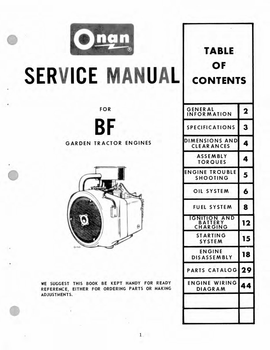
SER ICE U L FOR BF GARDEN TRACTOR ENGINES WE SUGGEST THIS BOOK BE KEPT HANDY FOR READY REFERENCE, EITHER FOR ORDERING PARTS OR MAKING ADJUSTMENTS. 1 TABLE OF CONTENTS GENERAL 2 INFORMATION SPECIFICATIONS 3 DIMENSIONS AND 4 CLEARANCES ASSEMBLY 4 TORQUES ENGINE TROUBLE S SHOOTING OIL SYSTEM 6 FUEL SYSTEM 8 rGNITlON. AND BATTERY 12 CHARGING STARTINO lS SYSTEM ENGINE 18 DISASSEMBLY PARTS CATALOG 29 ENGINE WIRING 44 DIAGRAM another free manual from www.searstractormanuals.com
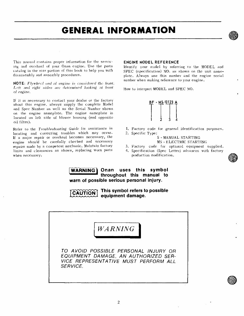
GENERAL INFORMATION This manual contains proper information for the servic- ing and overhaul of your Onan engine. Use the parts catalog in the rear portion of this book to help you with disassembly and assembly procedures. NOTE: Flywheel end of engine is considered the front. Left and right sides are determined looking at front of engine. If it is necessary to contact your dealer or the factory about this engine, always supply the complete Model and Spec Number as well as the Serial Number shown on the engine nameplate. The engine nameplate is located on left side of blower housing (end opposite oil filter), Refer to the Troubleshooting Guide for assistance in locating and correcting troubles which may occur. If a major repair or overhaul becomes necessary, the engine should be carefully checked and necessary repairs made by a competent mechanic. Maintain factory limits and clearances as shown, replacing worn parts when necessary. ENGINE MODEL REFERENCE Identify your model by referring to the MODEL and SPEC (specification) NO. as shown on the unit name- plate. Always use this number and the engine serial number when making reference to your engine. How to interpret MODEL and SPEC NO. rrT1 1. Factory code for general identification purposes. 2. Specific Type: S - MANUAL STARTING MS - ELECTRIC STARTING 3. Factory code for optional equipment supplied. 4. Specification (Spec Letter) advances with factory prod uchon modification. I WARNING' Onan uses this symbol throughout this manual to warn of possible serious personal Injury. ~ Thi~ symbol refers to possible equipment damage. WARNING I TO A VOID POSSIBLE PERSONAL INJURY OR EQUIPMENT DAMAGE, AN AUTHORIZED SER- VICE REPRESENTA TlVE MUST PERFORM ALL SERVICE. 2 another free manual from www.searstractormanuals.com
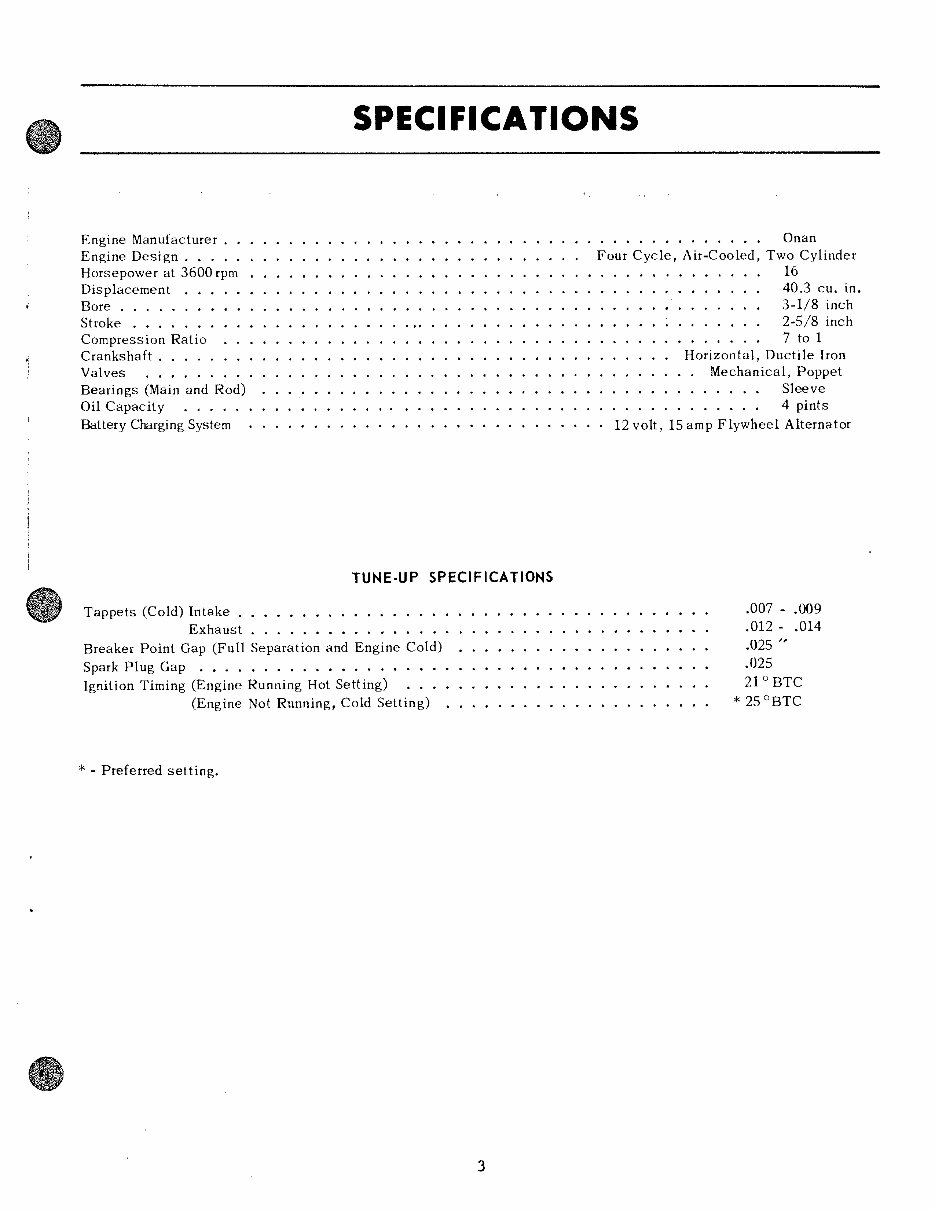
SPEC I FICA liONS Engine Manufacturer. . Engine Design. . . . . Horsepower at 3600 rpm Displacement Bore ....... . Stroke ...... • Compression Ratio Crankshaft. . . . . Valves ..... . Bearings (Main and Rod) Oil Capacity ..... Battery Charging System TUNE·UP SPECIFICATIONS Tappets (Cold) Intake . . . . . . • . Exhaust ....... • ........ Breaker Point Gap (Full Separation and Engine Cold) Spark Plug Gap . . . . . . . . . . . • . . • . . •. Ignition Timing (Engine Running Hot Setting) (Engine Not Running, Cold Setting) * - Preferred setting. 3 . . . . . . . . . . . . .. Onan Four Cycle, Air-Cooled, Two Cylinder 16 40.3 cu. in. 3-1/8 inch 2-5/8 inch 7 to 1 Horizontal, Ductile Iron Mechanical, Poppet . . . . . .. Sleeve . . . . . .• 4 pints 12 volt, 15 amp Flywheel Alternator .007 - .009 .012 - .014 .025 " .025 21 ° BTC * 25 °BTC another free manual from www.searstractormanuals.com
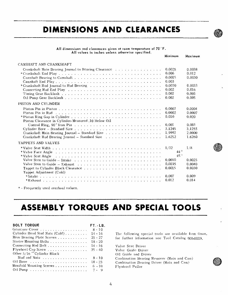
DIMENSIONS AND CLEARANCES All dimensions and clearances given at room temperature of 70°F. All values in inches unless otherwise specified. CAMSHAFT AND CRANKSHAFT Crankshaft Main Bearing Journal to Bearing Clearance * Crankshaft End Play ..... Camshaft Bearing to Camshaft . . . . . Camshaft End Play . . . . . . . . . . . * Crankshaft Rod J oumal to Rod Bearing Connecting Rod End Play Timing Gear Backlash . Oil Pump Gear Backlash PISTON AND CYLINDER Piston Pin in Piston . Piston Pin in Rod . . * Piston Ring Gap in Cylinder Piston Clearance in Cylinder-Measured .10 Below Oil Control Ring, 90 ° from Pin . . . . . . . . . . Cylinder Bore - Standard Size ......... . Crankshaft Main Bearing J oumal - Standard Size Crankshaft Rod Bearing Journal - Standard Size TAPPETS AND VALVES *Valve Seat Width. * Valve Face Angle .. * Valve Seat Angle Valve Stem to Guide - Intake Valve Stem to Guide - Exhaust Tappet to Cylinder Block Clearance Tappet Adjustment (Cold) * Intake. *Exhaust ....... . * - Frequently used overhaul values. Minimum Maximum 0.0025 0.0038 0.006 0.012 0.0015 0.0030 0.003 0.0020 0.0033 0.002 0.016 0.002 0.003 0.002 0.005 0.0002 0.0004 0.0002 0.0007 0.010 0.020 0.001 0.003 3.1245 3.1255 1.9992 2.0000 1.6252 1.6260 1/32 1/8 44 ° 4') ° 0.0010 0.0025 0.0035 0.0040 0.0015 0.0030 0.007 0.009 0.012 0.014 ASSEMBLY TORQUES AND SPECIAL TOOLS BOLT TORQUE Gearcase Cover .......... . Cylinder Head Stud Nuts (Cold) . Rear Bearing Plate Screws .. Starter Mounting Bolts ...... . Connecting Rod Bolt ....... . Flywheel Cap Screw ....... . Other 5/16 "Cylinder Block Stud and Nuts ......... . Oil Base ............... . .... . Manifold Mounting Screws ....... • ..... Oil Pump ...................... . FT.· LB. 8 - 10 14 - 16 25 - 27 18 - 20 14 - 16 35 - 40 8 - 10 18 - 23 6 - 10 7 - 9 4 The following special tools are available from Onan, for further information see Tool Catalog 900-0019. Valve Seat Driver Valve Guide Driver Oil Guide and Driver Combination Bearing Remover (Main and Cam) Combination Bearing Driver (Main and Cam) Flywheel Puller another free manual from www.searstractormanuals.com
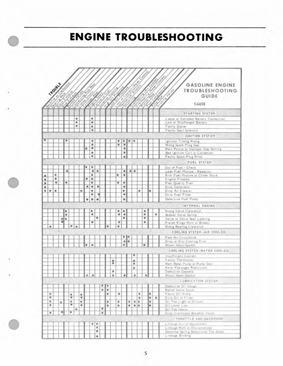
• I. I. • I. • • • • • • • • • • • . - • ENGINE TROUBLESHOOTING • • • • • • • • • • • • • • • . • • • • • • • • • • • • • • • • • • e e • • • • • - • • • - • b el" • • • • • • • • • • • • • • • • • e • • • • - - • • GASOLINE ENGINE TROUBLESHOOTING GUIDE CAUSE STARTIHC SYSTEM L .... se o. CO<tOd,,'" Batle'Y C"" "" CUOft Low a' Q'SC'""'lcd 8llne.)' ICHITIO ... SYSTEM .... arn Po ,n .. DI Imprope ' G-co s.- Itln l ea" Il[nll ' OI' Co d 0' Conde"''' ' FUEL SYSTEM QUI 01 Fuel· Ch,,(I, Lean F"" I Mlxlure · Re~dl"" En,,"e Floc.IeJ P .... r Quail,), Fuel 0, ..... Fuel F l ite! DeleChvl! Fu(" Pumo INTERNAL EHGINE COOLING SYSTEM I AU\ COOI.EO) I I I I I I I • I I I • I I 1- •• I l~ 11-.+-1_11~~p~""~'~"'~"~C ,,, ~c~ul ~ a" "~ "" ~ ______________ -i 1 I I I I I I • I J I I I I I ••• I I TT T I OU'l' '" Q llv Coolo" J[ FIns I I I I I I 1.-'.' , I' I T.T T T I e. I I Blown HU d Cu\e l COOLING SYSTEM ( WATER COOLEO I In sutl.c ... , ,, CODIMI ... ... • • • "'ald P •• Upl R,," trICied • O.",, < .. ~ .. c...k"," __ ._. ~~~~~~~~~--4~-~:.L-J--L~~.~~~.:~~~.~-J-=.~J-~~~8gl~D~w~ ~ H~e~.a~ ld ~Ga~'k~''' ~I _________________ -t L UBR ICA ION S ST M • - Oete cu w. Oil CAl.l te • • R.I ,.. I v"i .. " S.uc k • • • • • • - Fau lty 0 11 Purr:> • • - • • • Dluy Oil 0' 'F-ilr e , • I. • • • • • • • • 0 11 T .... L. lh l 0' D.'!~L __ --- • I- • - • • • • • O d L e .. ,, 1 Low • I· 0-" Too HI: nvw • • I· • OU 'Y CII, nlc.utl Bt eAlhe, VnlYe THROT TL E AND GOVER OR • • LI~k4l re Wlltn or DI,c.ann"CIl'd __ Gove rnor Sp ron E Sens lI,vlIY Too G, e 4l1 • 5 another free manual from www.searstractormanuals.com
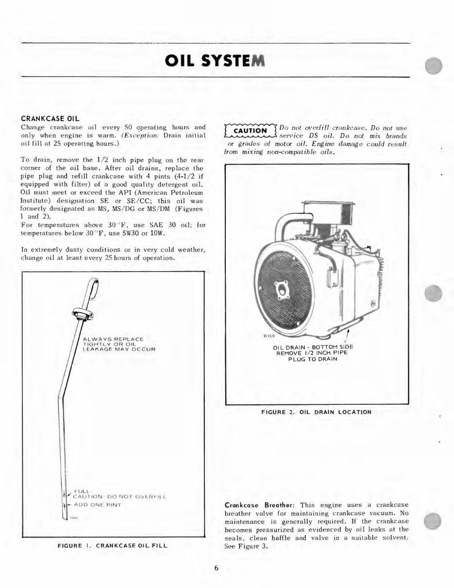
OIL SYSTE M CRANKCASE OIL Change crankcase oil every 50 operating hours and only when engine is warm. (Exc~ption« Drain initial oil fill at 25 operating hours.) To drain, remove the 1/2 inch pipe plug on the rear corner of the oil base. After oil drains, replace the pipe plug and refill crankcase with 4 pints (4-1/2 if equipped with filter) of a good quality detergent oil. Oil must meet or exceed the API (American Petroleum Institute) designation SE or SE/CC; this oil was formerly designated as MS, MS/DG or MS/DM (Figures 1 and 2). For temperatures above 30 "F, use SAE 30 oil; for temperatures below 30 of, use 5W30 or lOW. In extremely dusty conditions or in very cold weather, change oil at least every 25 hours of operation. ALWAYS REPLACE TIGHTLY OR OIL LEAKAGE MAY OCCUR I fULL ~ / CAU110N- DO NO 1 OVLRI-Ill f - ADD ONE PINT FIGURE I. CRANKCASE OIL FILL 6 ~ Do not overfill crankcase. Do not use ~ service DS oil. Do not mix brands or grades of motor oil. Engine damage could result from mixing non-compatible oils. OIL DRAIN - BOTTOM SIDE REMOVE 1/2 INCH PIPE PLUG TO DRAIN FIGURE 2. OIL DRAIN LOCATION Crankcase Breather: This engine uses a crankcase breather valve for maintaining crankcase vacuum. No maintenance is generally required. If the crankcase becomes pressurized as evidenced by oil leaks at the seals, clean baffle and valve in a suitable solvent. See Figure 3. another free manual from www.searstractormanuals.com
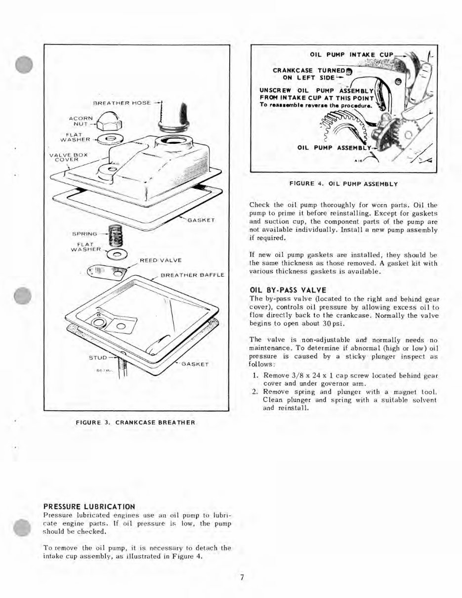
BR EA THE R H OS E - - FL AT W AS H ER ~ ~ RE ED VALVE / BREATHER BAF F LE FIGURE 3. CRANKCASE BREATH ER PRESSURE LUBRICATION P res s ure lubri cated eng in es us e an oil pu mp to lubri- cate e ngin e parts. If o il pr ess ure is low, th e pump s hould be che ck e d. To remove the o il pump, it is necess ary to det ac h th e intak e cup as sembly, as ill us trat ed in Figure 4. 7 CRANKCASE TURNED!!!) ON LEFT SIDE'- ---- OIL FIGURE 4. OIL PUMP ASSEMBLY Check the o il pump t horou g hly for worn pa rts. Oil th e pump to prime it befor e reinstalling. E xcept for ga sk ets a nd sucti on cup, the compo nen t part s of the pump a re not ava ilabl e individu a ll y. Inst a ll a new pump a sse mbl y if req uired. If new oi l pump ga s kets a re install e d, th ey sh ould be t he sa me t hicknes s as those remo ved. A gas ket kit with var io us thi c kne ss gas ke ts is av a ilabl e. OIL BY·PASS VALVE The by -pass va lve (l oc ated to the ri g ht and behind gea r c ove r), c ontrol s oil pre ss ure by a llo wing excess o il to flow directly bac k to the crankca se. Norm a lly th e val ve begin s to open a bout 3 0 ps i . The valv e is non- a djust a ble a nd normall y ne e ds no maintenan ce. To det ermine if abnorma l ( hi gh or low) oi l pres s ure is caus ed by a stick y plunger inspe ct as foll ows : 1. Re mov e 3 /8 x 24 x 1 ca p s cre w l oca ted behind gea r cov er and under gover nor a rm. 2. Re move spring a nd plunge r with a ma gne t tool. Cl ea n plunger a nd sp ring with a s uit a ble so lvent and re inst a ll. another free manual from www.searstractormanuals.com
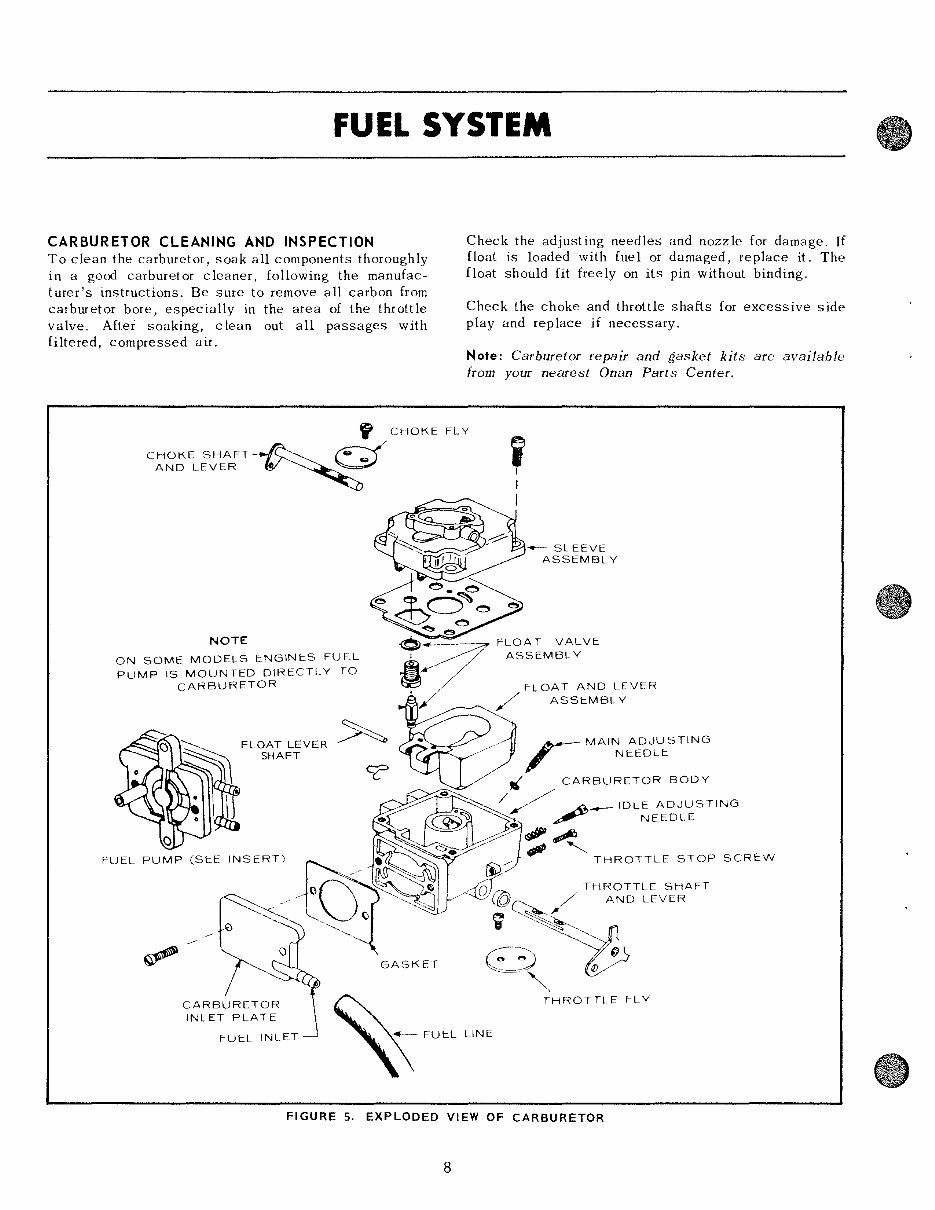
FUEL SYSTEM CARBURETOR CLEANING AND INSPECTION To clean the carburetor, soak all components thoroughly in a good carburetor cleaner, following the manufac- turer's instructions. Be sure to remove all carbon from carburetor bore, especially in the area of the throttle valve. After soaking, c lean out all passages with filtered, compressed air. Check the adjusting needles and nozzle for damage. If float is loaded with fue 1 or damaged, replace it. The float should fit freely on its pin without binding. Check the choke and throttle shafts for excessive side play and replace if necessary. Note: Carburetor repair and gasket kits are available from your nearest On an Parts Center. ~ CHOKE FLY CHOKE SHAFT-~~ d ~ AND LEVER "" ~ , NOTE ON SOME MODELS ENGINES FUEL PUMP IS MOUNTED DIRECTLY TO CARBURETOR FUEL PUMP (SEE INSERT) CARBURETOR INLET PLATE FUEL INLET GASKET - SLEEVE ASSEMBLY LEVER ASSEMBLY THROTTLE STOP SCREW o fA THROTTLE SHAFT ~ / AND LEVER . ~ B, THROTTLE FLY FIGURE 5. EXPLODED VIEW OF CARBURETOR 8 another free manual from www.searstractormanuals.com
Our Onan 16 HP BF Engine Service & Parts Manual is an essential resource for anyone involved in car repair. Whether you're a professional mechanic or a DIY enthusiast, this manual provides detailed information on servicing and maintaining the Onan 16 HP BF engine.
With comprehensive sections covering parts identification, troubleshooting, and maintenance procedures, this manual equips you with the knowledge needed to keep the Onan 16 HP BF engine in optimal condition. It's an invaluable tool for diagnosing issues and carrying out repairs with confidence.
Whether you prefer the convenience of a .PDF manual or the versatility of a .OVA file manual, this resource is designed to support your needs. Invest in the Onan 16 HP BF Engine Service & Parts Manual and empower yourself with the expertise required to tackle engine-related challenges effectively.