

POWERHOUSE GeneratorS ph2100pri service manual
What's Included?
Fast Download Speeds
Online & Offline Access
Access PDF Contents & Bookmarks
Full Search Facility
Print one or all pages of your manual

1 PH2100PRI SM 04-27-2011
POWERHOUSE POWER PRODUCTS
PH2100PRi SHOP MANUAL
Coast Distribution
April, 2011
POWERHOUSE®
Downloaded from www.Manualslib.com manuals search engine

2 PH2100PRI SM 04-27-2011
Preface
This manual covers the construction, function and servicing procedure of the
POWERHOUSE® PH2100PRi generator, certificated by CARB.
Careful observance of these instructions will result in better, safe service work.
All information, illustrations, directions and specifications included in this publication are based on
the latest product information available at the time of approval for printing. Coast Distribution
Systems, Inc. reserves the right to make changes without incurring any obligation whatever. No part
of this publication may be reproduced without written permission.
Downloaded from www.Manualslib.com manuals search engine

3 PH2100PRI SM 04-27-2011
CONTENTS
Preface ......................................................................................................................................................... 2
CONTENTS .................................................................................................................................................. 3
1. SPECIFICATIONS.................................................................................................................................... 5
1.1 SPECIFICATIONS .............................................................................................................................. 5
1.2 CHARACTERISTICS.......................................................................................................................... 6
1.3 Wiring diagram.................................................................................................................................... 7
2 Service Information ................................................................................................................................... 8
2.1 The importance of proper servicing .................................................................................................... 8
2.2 Important safety precautions .............................................................................................................. 8
2.3 Service rules ....................................................................................................................................... 9
2.4 Serial number location ...................................................................................................................... 10
2.5 Engine maintenance standards ........................................................................................................ 10
2.6 Motor ................................................................................................................................................. 11
2.7 Torque values ................................................................................................................................... 12
3.Trouble shooting...................................................................................................................................... 13
3.1 General symptoms and possible causes ......................................................................................... 13
3.2 Difficult cold starting ......................................................................................................................... 14
3.3 Hard starting ..................................................................................................................................... 15
3.3 Cylinder compression check ............................................................................................................ 16
3.4 Ignition system .................................................................................................................................. 17
3.5 Engine oil level is low, but engine does not stop.............................................................................. 19
3.6 Engine stops running (Throttle is in the correct position)................................................................. 19
3.7 Engine speed can‟t increase or unstable (choke is at the correct position) .................................... 20
3.8 Engine speed too high or too low ..................................................................................................... 20
3.9 Engine speed doesn‟t increase with economy system “ON” and a load connected. ...................... 21
3.10 No or low AC output........................................................................................................................ 21
3.11 Measuring stator output voltage while running............................................................................... 22
3.12 No DC output at receptacle. ........................................................................................................... 23
3.13 Battery will not charge. ................................................................................................................... 23
3.14 Voltage regulator ............................................................................................................................ 24
3.15 Starter motor doesn‟t run. ............................................................................................................... 25
3.16 No output when operating in Parallel: ............................................................................................ 26
3.17 Parallel operating procedure: ......................................................................................................... 27
3.18 Troubleshooting Parallel Operation: ............................................................................................... 29
4. Maintenance schedule ........................................................................................................................... 31
4.1 Maintenance schedule...................................................................................................................... 31
4.2 Checking the oil level........................................................................................................................ 32
4.3 Changing oil ...................................................................................................................................... 32
4.9 Evaporation Control .......................................................................................................................... 38
5 Muffler system ......................................................................................................................................... 40
6. Carburetor .............................................................................................................................................. 43
7. Control panel .......................................................................................................................................... 48
8. Outer generator housing ........................................................................................................................ 49
9. Recoil starter / Electric Starter / Ignition coil .......................................................................................... 50
10. Rotor/Stator disassembly / reassembly ............................................................................................... 55
Downloaded from www.Manualslib.com manuals search engine

4 PH2100PRI SM 04-27-2011
11. Exploded engine view .......................................................................................................................... 57
12. Valve cover/ Rocker arm ...................................................................................................................... 60
Downloaded from www.Manualslib.com manuals search engine

5 PH2100PRI SM 04-27-2011
1. SPECIFICATIONS
1.1 SPECIFICATIONS
Dimensions and weights
Model PH2100PRI
Overall Length 22 in. (559mm)
Overall Width 11 in. (279mm)
Overall Height 19 in. (482mm)
Net Weight, with battery 73 lbs. (33kg)
Engine
Model 152F
Type 4-stroke,OVH, single cylinder, Gasoline engine
Displacement 125cc
Bore x stroke 52.4Χ57.8 mm
Maximum horsepower 4.35 Hp
Compression ratio 9.2:1
Cooling system Forced air-cooled
Ignition system Electronic
Spark plug A7RTC
Carburetor Float type, Horizontal, butterfly valve type
Air cleaner Semi-dry type
Governor Electronic control type
Lubrication system Pump
Lube oil SAE 15W-40 (SF/SG grade or greater)
Oil capacity 15.6 fl oz (460 ml)
Starting system Recoil starter / Electric / Remote
Stopping system Primary circuit ground
Fuel used Automotive unleaded gasoline
Downloaded from www.Manualslib.com manuals search engine

6 PH2100PRI SM 04-27-2011
Alternator
Alternator type Multi pole rotation type
Alternator structure Self-ventilation drip-proof type
Excitation Self-excitation (Magnet type)
Phase Single phase
Rotating direction Clockwise (Viewed from the generator)
Frequency regulation AC-DC-AC conversion (Inverter type)
1.2 CHARACTERISTICS
Model PH2100PRi
Maximum output AC 2.1KVA
Rated output AC 2.0KVA
Rated output DC 100W
Rated frequency 60HZ
Rated voltage AC 120V
Rated voltage DC 12V
Rated current AC 16.7A
Rated current DC 8.3A
Power factor 1.0cosφ
Voltage variation rate Momentary
Average
Average time
10%max.
1.5%max.
3 sec. max.
Voltage stability ±1%
Frequency variation rate Momentary
Average
Average time
1%max.
1%max.
1 sec. max.
Frequency stability ±0.1%
Insulation resistance 10MΩmin.
AC circuit protector 20A
DC circuit protector 10A
Fuel tank capacity 1.3 gal (4.9L)
Continuous running time at Rated load
~ 1/4 load
3.0 ~ 7.5 hours
Noise level (Zero load to full load) 56~63 dB (A)/7m
Downloaded from www.Manualslib.com manuals search engine
7 PH2100PRI SM 04-27-2011
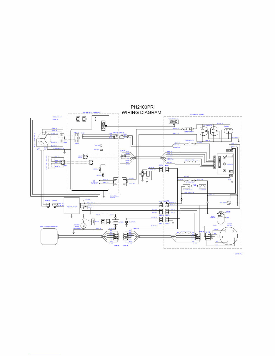
1.3 Wiring diagram
Downloaded from www.Manualslib.com manuals search engine

8 PH2100PRI SM 04-27-2011
2 Service Information
2.1 The importance of proper servicing
Proper servicing is essential to the safety of the operator and the reliability of the engine. Any error or
oversight made by the technician while servicing can easily result in faulty operation, damage to the
engine or injury to the operator.
Improper servicing can cause an unsafe condition that can lead to
serious injury or death.
Follow the procedures and precautions in this shop manual carefully.
Some of the most important precautions are given below. However, we
cannot warn you of every conceivable hazard that can arise in
performing maintenance or repairs. Only you can decide whether you
should perform a given task.
Failure to follow maintenance instructions and precautions can cause
you to be seriously hurt or killed. Follow the procedures and precautions
in this shop manual carefully.
2.2 Important safety precautions
Be sure you have a clear understanding of all basic shop safety practices and that you are wearing
appropriate clothing and safety equipment. When performing maintenance or repairs, be especially
careful of the following:
Read the instructions before you begin, and be sure you have the tools
and skills required to perform the tasks safely.
Be sure that the engine is off before you begin any maintenance or
repairs. This will reduce the possibility of several hazards:
a.) Exhaust gas contains poisonous carbon monoxide. Never run the
generator in an enclosed area.
b.) Be sure there is adequate ventilation whenever you run the
engine.
c.) The muffler becomes very hot during operation and remains hot
for several minutes after stopping the engine.
d.) Let the engine cool before you touch it.
e.) Keep away from moving parts while the generator is running.
Do not run the engine unless the instruction tells you to do so. Even
then, keep your hands, fingers, and clothing away.
Gasoline is extremely flammable and explosive under certain conditions.
To reduce the possibility of a fire or explosion, use caution when working
around gasoline, use only a nonflammable solvent, not gasoline, to clean
parts. Keep all cigarettes, sparks, and flames away from all fuel-related
parts.
Downloaded from www.Manualslib.com manuals search engine

9 PH2100PRI SM 04-27-2011
2.3 Service rules
1. Use genuine POWERHOUSE® or POWERHOUSE®-recommended parts and lubricants or their
equivalents. Parts that do not meet POWERHOUSE® design specifications may damage the
engine.
2. Always install new gaskets, O-rings, etc. when reassembling.
3. When tightening bolts or nuts, begin with larger-diameter or inner bolts first and tighten to the
specified torque diagonally, unless a particular sequence is specified.
4. Clean parts in cleaning solvent upon disassembly. Lubricate any sliding surfaces before
reassembly.
5. After reassembly, check all parts for proper installation and operation.
6. Many screws used in this machine are self-tapping. Be aware that cross-threading or over
tightening these screws will strip the threads and ruin the hole.
7. Use only metric tools when servicing this engine. Metric bolts, nuts and screws are not
interchangeable with non metric fasteners. The use of incorrect tools and fasteners will damage
the engine.
8. Follow the instructions represented by these symbols when they are used.
Electric precautions
1. Hold the connector body to disconnect the connector. Do not disconnect by pulling the wire
harness. To disconnect the locking connector, be sure to unlock first, and then disconnect.
2. Check the connector terminals for bent, excessive extrusion, missing terminal, or other
abnormalities before connecting the connector.
3. To connect, insert the connector as full as it goes. If the connector is a locking type, be sure that
it is locked securely.
4. Check the connector cover for breakage and check whether the connector female terminal is
open excessively. Then, connect the connector securely. Check the connector terminal for rust.
Remove the rust using an emery paper or equivalent material before connecting the connector.
5. Set the harness clips in the specified places of the frame securely, and clamp the wire
harnesses.
6. Clamp the wire harnesses securely so that they do not interfere with the rotating parts, moving
parts and the hot parts.
7. Route and connect the wire harnesses properly. Be sure that the harnesses are not loose,
twisted or pulled tight.
8. Route the wire harnesses properly so that they do not contact with the shape edges and corners,
and the end of the bolts and screws on the body.
9. If a wire harness contacts the end of the bolts/screws or sharp edges and corners, protect the
contact part of the harness with a tube or by winding with an electrician‟s insulating tape. If the
wire harness has a grommet, set the grommet securely.
10. Take care not to pinch the wire harnesses during installation of a part. If a wire harness has the
damaged insulation, repair by winding with the electrician‟s insulating tape.
11. Read the tester manufacture‟s operation instructions carefully before operation with tester.
Follow the instructions of the Service Manual. Be sure that the battery built in a tester is fully
charged and check the meter before inspection using the tester.
Downloaded from www.Manualslib.com manuals search engine
10 PH2100PRI SM 04-27-2011
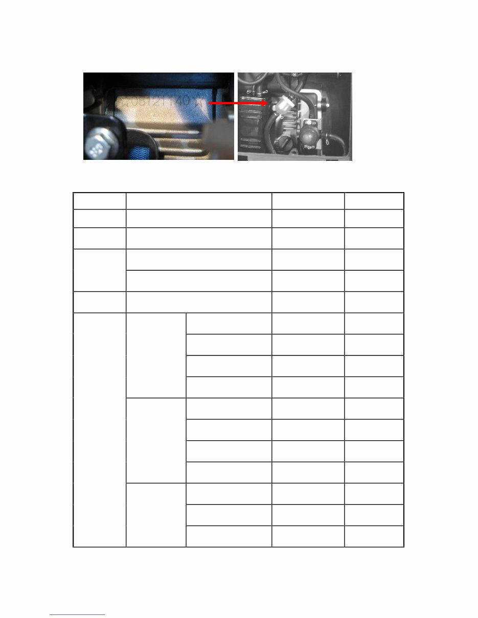
2.4 Serial number location
The serial number can be found stamped on the engine block above the oil dipstick. It is visible when the
maintenance panel is removed.
2.5 Engine maintenance standards
Part
Item Standard(mm)
Service limit
Engine Maximum speed without load 5000±100rpm
—
Cylinder Sleeve I.D.
52.400-52.420mm
(2.0630”~2.0638”
52.505mm
(2.0671”)
Piston
Skirt O.D
52.360-52.380mm
(2.061”~2.062”)
52.25mm
(2.057”)
Pin bore I.D.
15.002-15.008mm
(0.5907”~0.5908
15.05mm
(0.5925”)
Piston pin O.D
14.994-15.000mm
(0.5903”~0.5905”)
14.95mm
(0.588”)
Piston ring
1st ring
Height h
0.97-0.99mm
(0.0381”~0.0389”)
0.87mm
(0.0342”)
Ring side clearance
0.02-0.06mm
(0.0008”~0.0024”)
0.15mm
(0.0059”)
Ring end clearance
0.15-0.25mm
(0.0059”~0.0098”)
1.0mm
(0.039”)
Width t
1.90-2.10mm
(0.0748”~0.0826”)
1.80mm
(0.0590”)
2nd ring
Height h
0.97-0.99mm
(0.0381”~0.0389”)
0.87mm
(0.0342”)
Ring side clearance
0.02-0.06mm
(0.0008”~0.0024”)
0.15mm
(0.0059”)
Ring end clearance
0.15-0.25mm
(0.0059”~0.0098”)
1.0mm
(0.039”)
Width t
2.0-2.3mm
(0.0787”~0.0905”)
1.8mm
(0.0590”)
Oil ring
Height h
1.85-1.96mm
(0.0728”~0.0771”)
1.75mm
(0.0688”)
Ring side clearance
0.03-0.18mm
(0.001”~0.007”)
0.24mm
(0.009”)
Ring end clearance
0.20-0.50mm
(0.0078”~0.0196”)
1.0mm
(0.039”)
Serial
Number
Downloaded from www.Manualslib.com manuals search engine
You're Reading a Preview
What's Included?
Fast Download Speeds
Online & Offline Access
Access PDF Contents & Bookmarks
Full Search Facility
Print one or all pages of your manual
$27.99
Viewed 35 Times Today


Secure transaction
What's Included?
Fast Download Speeds
Online & Offline Access
Access PDF Contents & Bookmarks
Full Search Facility
Print one or all pages of your manual
$27.99
Get the service manual for the POWERHOUSE GENERATORS ph2100pri. This manual is available in .PDF format, making it compatible with all versions of Windows, Mac, and Linux. It is printable and can be accessed instantly at high speed. The only requirement is Adobe Reader. This comprehensive manual is a great value for professional mechanics and DIY enthusiasts alike.


