

KOHLER Service Parts Marine Generator 8C 8E 10C 10E 12.5C 12
What's Included?
Fast Download Speeds
Online & Offline Access
Access PDF Contents & Bookmarks
Full Search Facility
Print one or all pages of your manual
Marine Generator Sets
Models:
8C
8E
10C
10E
12.5C
12.5E
TP-5413 5/01c
Service Parts

Table of Contents
Introduction 1 .................................................................
Numbering System Significance 1 ...............................................
Illustrations 1 ..................................................................
How to Find Part Numbers 1 ....................................................
Hardware References 1 ........................................................
Specification Number Index 2 ...................................................
Group 1: Gaskets and Seals 4 ..................................................
Group 2: Cylinder Block 5 ......................................................
Group 3: Cylinder Head and Valves 6 ............................................
Group 4: Front Cover Assembly 7 ...............................................
Group 5: Camshaft and Valve Control 8 ..........................................
Group 5: Camshaft and Valve Control 9 ..........................................
Group 6: Crankshaft and Piston 10 ..............................................
Group 6: Crankshaft and Piston 11 ..............................................
Group 7: Flywheel and Clutch 12 ................................................
Group 8: Oil Pump and Pan 13 ..................................................
Group 9: Fan and Water Pump 14 ...............................................
Group 10: Intake Manifold 15 ...................................................
Group 12: Ignition Module and Spark Plugs 15 ....................................
Group 101: Air Intake 16 .......................................................
Group 103: Fuel System 17 ....................................................
Group 104: Cooling System 18 ..................................................
Group 105: Engine 22 .........................................................
Group 107: Nameplate and Decals 26 ...........................................
Group 108: Oil Pressure Switches 28 ............................................
Group 109: Skid and Plant Mounting 29 ..........................................
Group 110: Water Temperature Switches 30 ......................................
Group 112: Starter 31 ..........................................................
Group 201: Generator and Mounting 32 ..........................................
Group 301: Controller and Mounting 34 ..........................................
Group 01: Literature 36 ........................................................
Accessories 37 ................................................................
Appendix A Abbreviations A-1 ..................................................
Appendix B Common Hardware Application Guidelines A-3 .........................
Appendix C General Torque Specifications A-4 ....................................
Appendix D Common Hardware Identification A-5 .................................
Appendix E Common Hardware List A-6 .........................................

1 TP-5413 5/01
Introduction
This manual lists service replacement parts for
8--12.5 kW generator sets.
At the time of print this manual applied to the generator
set specification (spec) numbers listed in the
Specification Number Index. On occasion this manual
may apply to specs not listed in the Specification
Number Index.
Information in this publication represents data available
at the time of print. Kohler Co. reserves the right to
change this publication and the products represented
without notice and without any obligation or liability
whatsoever.
This manual includes the following main sections:
Table of Contents. Lists the sections of the manual.
Introduction (and other information sections).
Contains introductory material about part numbers,
illustrations, and hardware.
Specification Number Index. Lists the generator set
specs and groups.
Group Parts Lists. List the part numbers of parts in the
groups.
Kit Sections. List modules and accessories and their
parts.
Appendices. Include Abbreviations, Common
Hardware Application Guidelines, General Torque
Specifications, Common Hardware Identification, and
Common Hardware List.
x:in:004:002
Numbering System Significance
This manual uses the following numbering systems:
Specification Number. The product identification
number located on the generator set nameplate. Spec
numbers break down into groups.
Group Number. A unique number representing a parts
group needed to assemble a generator set function. For
example, Group 101 is the Air Intake group.
Variation or Module Number. A group might have
several variations. Each variation performs the same
function with different parts lists. For example, a 50 Hz
generator alternator and a 60 Hz generator alternator
both perform the same function, however, with different
parts. Each difference requires a group variation or
module number.
Part Number. The part number identifies an individual
assembly, subassembly, component, or accessory kit.
x:in:004:003:a
Illustrations
Illustrations (or exploded-view drawings) best
representing the widest range of variations accompany
most groups in this manual. Illustrations do not depict all
details and may not show all parts. Do not use
illustrations for assembly or disassembly instructions.
x:in:004:004
How to Find Part Numbers
Use the following steps to locate a service replacement
part.
1. Locate the generator set nameplate to identify the
generator set spec number .
2. Locate a second generator set nameplate listing
accessories to identify installed modules. On
some models the accessory nameplate is mounted
inside the generator junction box.
3. Turn to the Specification Number Index. The
first column lists the generator set spec numbers.
The headings identify the groups of parts that make
up the generator set.
4. Identify the group most likely to include the
service part number.
5. Find the group variation number at the
intersection of the spec number row and the group
column. Note the variation number.
6. Page forward to locate the group identified in
step 4 or find the appropriate page in the Table of
Contents.
7. Find the part on the illustration and note the item
number of the part or find the part description in
the parts list.
8. Select the part number that corresponds to
your group variation. The first column lists the
illustration item number. Find the variation
identified in the Specification Number Index or the
module number found on the generator set
nameplate in the appropriate column on the right
side of the parts list table. Find the quantity used at
the intersection of the item number row and the
variation column. A blank space at the intersection
means the variation/module does not use that part
number.
x:in:004:005
Hardware References
Many common hardware items do not appear in parts
manuals or will appear as common hardware entries. A
common hardware entry lists the size of the hardware.
For example, an item that appears as “Hardware,
3/8-16” in the text means that the piece is 3/8-16 size.
Obtain common hardware locally or, if contacting the
factory, use the Common Hardware List in the appendix
to identify the common hardware part number and
specifications. See Common Hardware Application
Guidelines in the appendix for mating hardware
instructions.
Some hardware items require a specific size or some
other characteristic. In that case, use the part number
listed in the text.
When replacing hardware, do not substitute inferior
grade hardware. Replacement hardware grade should
be equal to or better than the grade of the
manufacturer’s original hardware. Use the Common
Hardware List in the appendix to identify the common
hardware hardness.
x:in:004:006
2 TP-5413 5/01
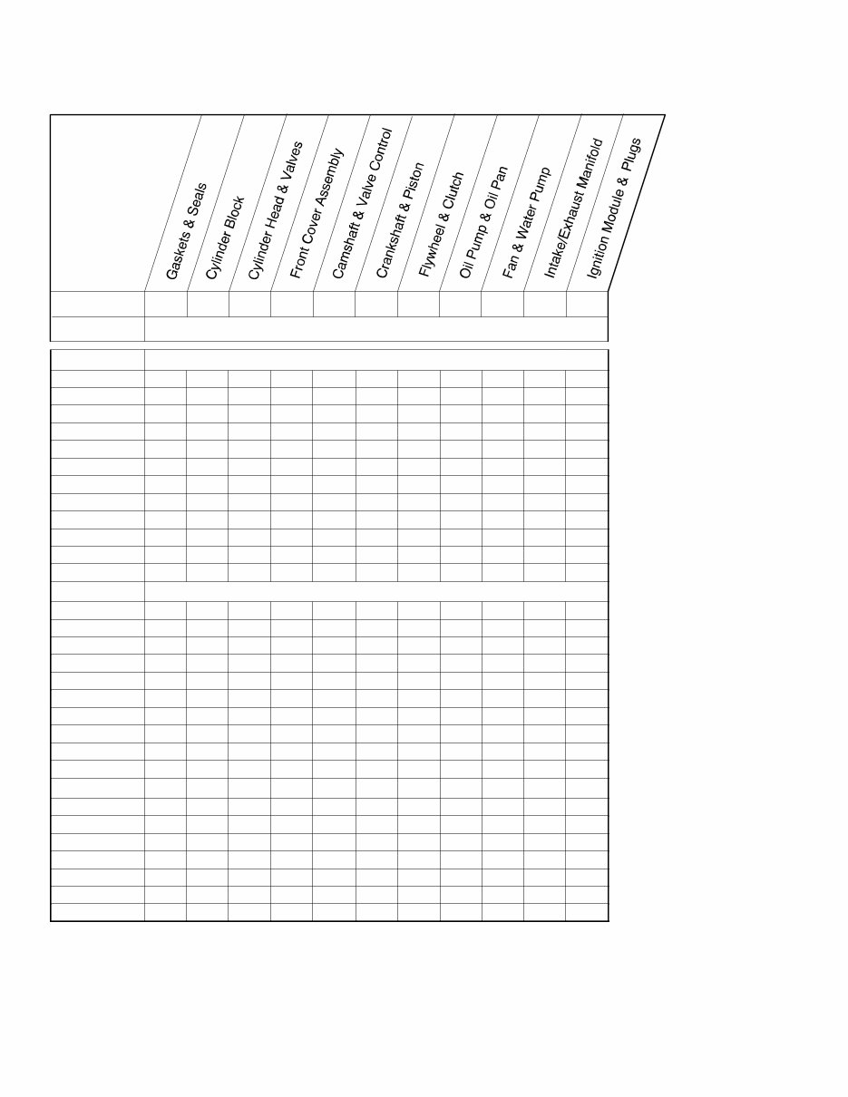
Specification Number Index
Group No. 1 2 3 4 5 6 7 8 9 10 12
Spec No. Variation Number
Group Title
8C/8E
PA-110302 1 1 1 1 1 1 1 1 1 1 1
PA-110303 3 3 1 1 1 3 3 3 1 1 1
PA-110305 3 3 1 1 1 3 3 3 1 1 1
PA-110306 3 3 1 1 1 3 3 3 1 1 1
PA-110307 3 3 1 1 1 3 3 3 1 1 1
PA-110308 3 3 1 1 1 3 3 3 1 1 1
PA-110309 3 3 1 1 1 3 3 3 1 1 1
PA-110310 3 3 1 1 1 3 3 3 1 1 1
PA-110311 2 2 2 1 2 2 2 2 1 1 1
PA-110312 2 2 2 1 2 2 2 2 1 1 1
GM17772-GA1 2 2 2 1 2 2 2 2 1 1 1
10C/10E
PA-110105 1 1 1 1 1 1 1 1 1 1 1
PA-110106 1 1 1 1 1 1 1 1 1 1 1
PA-110109 1 1 1 1 1 1 1 1 1 1 1
PA-110110 3 3 1 1 1 3 3 3 1 1 1
PA-110111 3 3 1 1 1 3 3 3 1 1 1
PA-110112 3 3 1 1 1 3 3 3 1 1 1
PA-110113 3 3 1 1 1 3 3 3 1 1 1
PA-110114 2 2 2 1 2 2 2 2 1 1 1
GM17772-GA2 2 2 2 1 2 2 2 2 1 1 1
12.5C/12.5E
PA-110205 2 2 2 1 2 2 2 2 1 1 1
PA-110206 2 2 2 1 2 2 2 2 1 1 1
PA-110209 2 2 2 1 2 2 2 2 1 1 1
PA-110210 2 2 2 1 2 2 2 2 1 1 1
PA-110211 2 2 2 1 2 2 2 2 1 1 1
PA-110212 2 2 2 1 2 2 2 2 1 1 1
GM17772-GA3 2 2 2 1 2 2 2 2 1 1 1
3 TP-5413 5/01
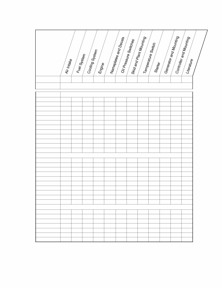
Specification Number Index
Group No. 101 103 104 105 107 108 109 110 112 201 301 701
Spec No. Variation Number
Group Title
8C/8E
PA-110302 2 4 7 20 13 1 3 2 2 3 18 10
PA-110303 2 4 7 23 17 -- 3 2 2 3 19 10
PA-110305 2 4 7 23 26 -- 3 2 2 3 19 10
PA-110306 2 4 17 28 26 -- 3 2 2 3 24 10
PA-110307 6 12 18 31 28 -- 16 2 2 32 26 11
PA-110308 6 12 19 31 28 -- 16 2 2 32 27 11
PA-110309 6 17 19 31 30 -- 16 2 2 32 27 11
PA-110310 6 17 18 31 30 -- 16 2 2 32 26 11
PA-110311 6 17 19 32 48 -- 16 2 2 32 27 11
PA-110312 6 17 18 32 48 -- 16 2 2 32 26 11
GM17772-GA1 6 GR4 18 GR1 48 -- 16 2 2 32 GR2 11
10C/10E
PA-110105 2 4 7 5 2 1 3 2 2 7 3 10
PA-110106 2 4 11 20 13 1 3 2 2 7 14 10
PA-110109 2 4 11 20 13 1 3 2 2 7 16 10
PA-110110 2 4 7 23 17 -- 3 2 2 7 19 10
PA-110111 2 4 7 23 26 -- 3 2 2 7 19 10
PA-110112 6 12 18 29 28 -- 16 2 2 33 26 11
PA-110113 6 17 18 29 30 -- 16 2 2 33 26 11
PA-110114 6 17 18 33 48 -- 16 2 2 33 26 11
GM17772-GA2 6 GR4 18 GR1 48 -- 16 2 2 33 GR2 11
12.5C/12.5E
PA-110205 2 4 7 6 11 1 4 2 2 4 4 10
PA-110206 2 4 7 19 14 1 4 2 2 4 15 10
PA-110209 2 4 7 19 14 1 4 2 2 4 17 10
PA-110210 2 4 7 19 27 -- 4 2 2 4 17 10
PA-110211 6 12 18 30 29 -- 15 2 2 31 25 11
PA-110212 6 17 18 30 31 -- 15 2 2 31 25 11
GM17772-GA3 6 GR4 18 GR1 48 -- 15 2 2 31 GR3 11
4 TP-5413 5/01
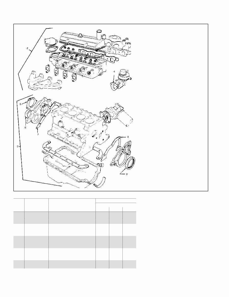
Group 1: Gaskets and Seals
Upper and Lower Engine Gasket Kits (Items 2 and 3)
do not include Items 4-9.
Upper Gasket Kit does not include a cylinder head gasket.
Order cylinder head gasket separately from Group 3.
Quantity
Variation Number
Item Part Number Description 1 2 3
1 224704 Engine gasket kit, complete 1 1
1 224705 Engine gasket kit, complete 1
2 224706 Engine gasket kit, upper 1 1
2 224707 Engine gasket kit, upper 1
3 279143 Engine gasket kit, lower 1 1
3 279145 Engine gasket kit, lower 1
4 246058 Gasket, fuel pump 1 1 1
5 224773 Gasket, water pump 1 1 1
6 279112 Seal, front cover 1 1 1
7 224722 Gasket, front cover 1 1 1
8 224748 Gasket, rear retainer 1
8 224749 Gasket, rear retainer 1 1
9 224782 Seal, crankshaft rear 1
9 276192 Seal, crankshaft rear 1 1
5 TP-5413 5/01
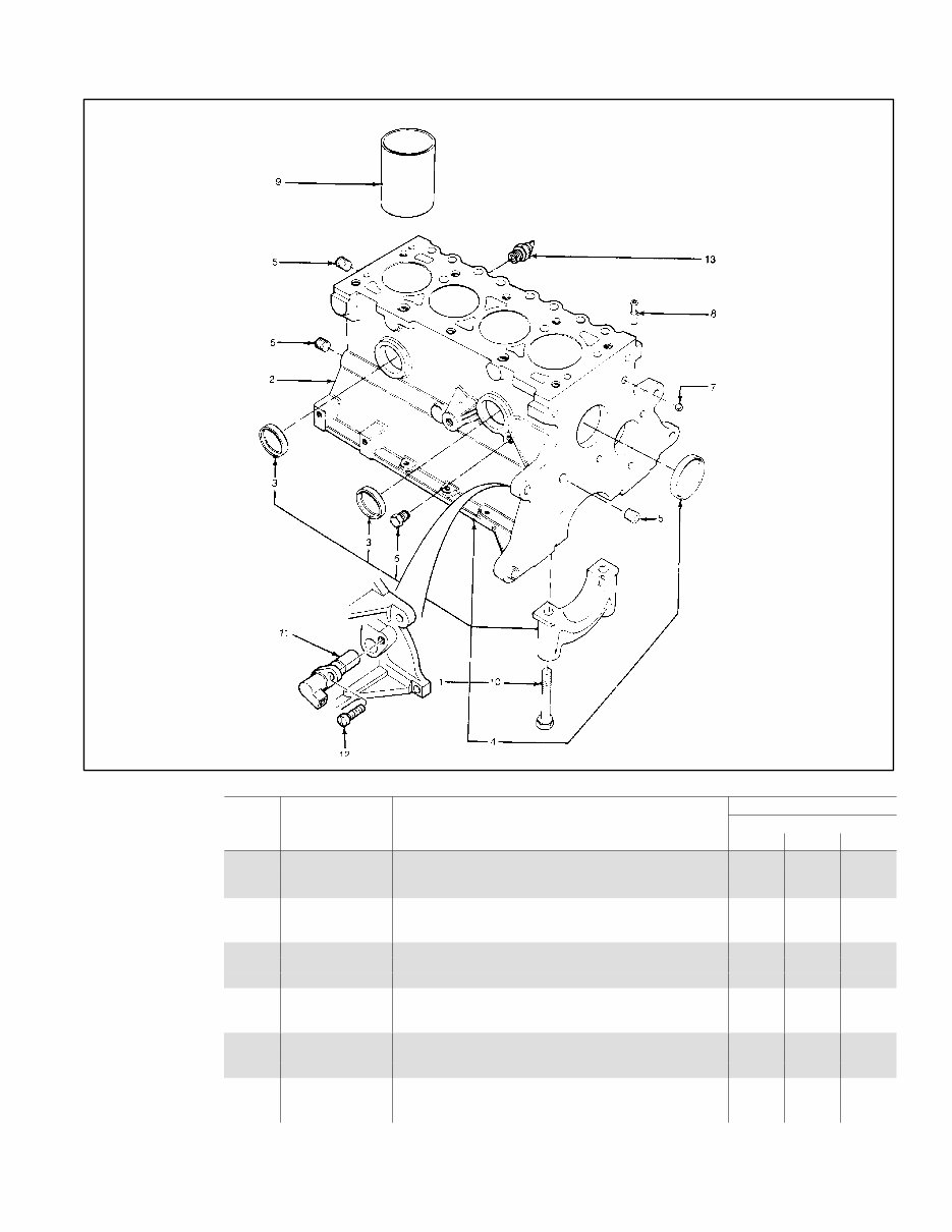
Group 2: Cylinder Block
Quantity
Variation Number
Item Part Number Description 1 2 3
1 276194 Block, cylinder (basic) 1
1 224718 Block, cylinder (basic) 1
1 224717 Block, cylinder (basic) 1
2 224719 Block, cylinder (includes crank, pistons, rings, etc.) 1
2 276195 Block, cylinder (includes crank, pistons, rings, etc.) 1
2 224720 Block, cylinder (includes crank, pistons, rings, etc.) 1
3 279188 Plug, 41.6 mm 2 2 2
4 279187 Plug, 51 mm 1 1 1
5 # Plug, 1/4 NPT 3 3 3
6 # Plug, 1/4 NPT 1 1 1
7 279214 Plug, ball (oil gallery) 1 1 1
8 279193 Adapter 1 1 1
9 224726 Liner, cylinder 4 4
9 224727 Liner, cylinder 4
10 279173 Bolt, main bearing cap 6 10 10
11 224716 Transducer (speed sensor) 1 1 1
12 # Screw, M6 x 14 1 1 1
13 276456 Switch, oil pressure 1 1 1
# Common hardware; procure locally.
6 TP-5413 5/01
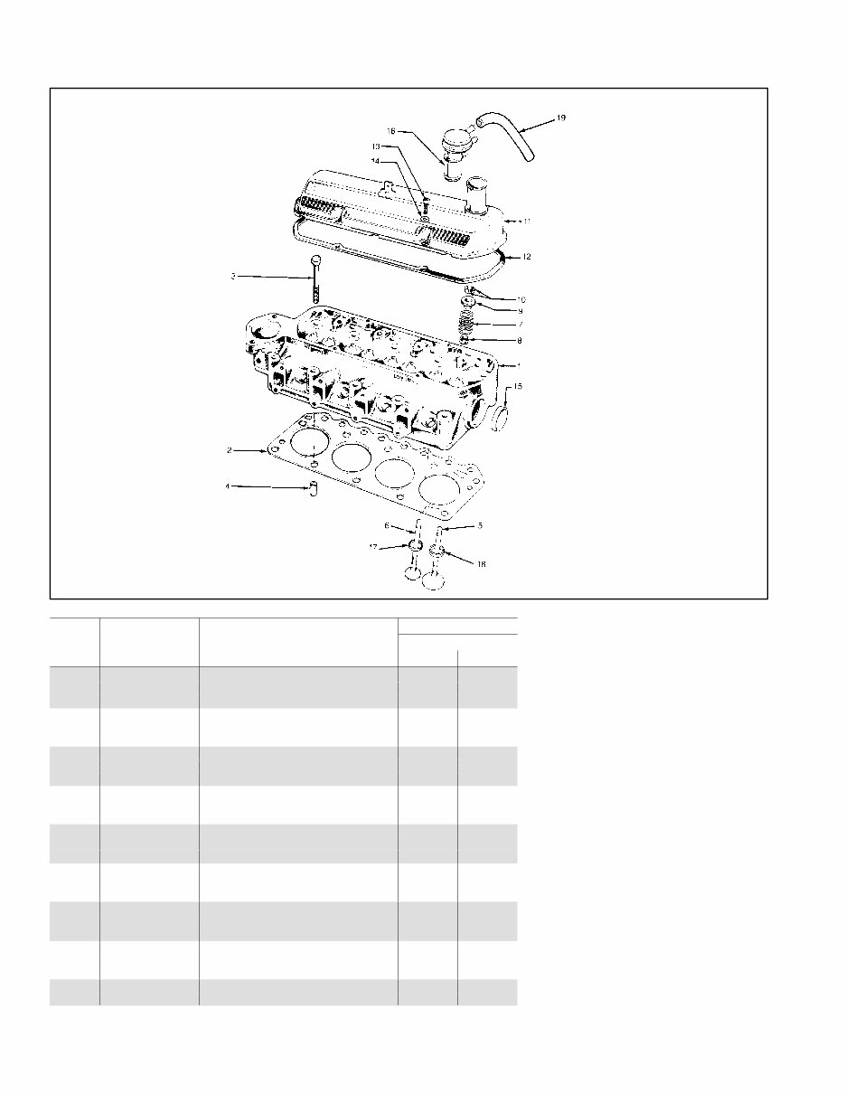
Group 3: Cylinder Head and Valves
Quantity
Variation Number
Item Part Number Description 1 2
1 GM24858 Cylinder head assembly 1
1 224723 Cylinder head assembly 1
2 224724 Gasket, cylinder head 1
2 224725 Gasket, cylinder head 1
3 224731 Bolt, cylinder head 10 10
4 224791 Dowel, cylinder head to block 2 2
5 224755 Valve, intake, standard 4
5 224757 Valve, intake, standard 4
5 224756 Valve, intake, 0.40 oversized 4
5 224758 Valve, intake, 0.40 oversized 4
6 224754 Valve, exhaust, standard 4 4
6 224753 Valve, exhaust, 0.40 oversized 4 4
7 224759 Spring, valve 8 8
8 224709 Seal, valve stem 8 8
9 224770 Retainer 8 8
10 224708 Lock, valve spring 16 16
11 224762 Cover, rocker arm 1 1
12 279084 Gasket, rocker arm cover 1 1
13 224789 Screw, rocker cover/head 4 4
14 # Washer, flat, 6 mm 4 4
15 279188 Plug, 41.6 mm 1 1
16 279115 Cap, oil, breather 1 1
17 224730 Insert, exhaust valve seat 4 4
18 224728 Insert, intake valve seat 4
18 224729 Insert, intake valve seat 4
19 224794 Hose, PCV 1 1
7 TP-5413 5/01
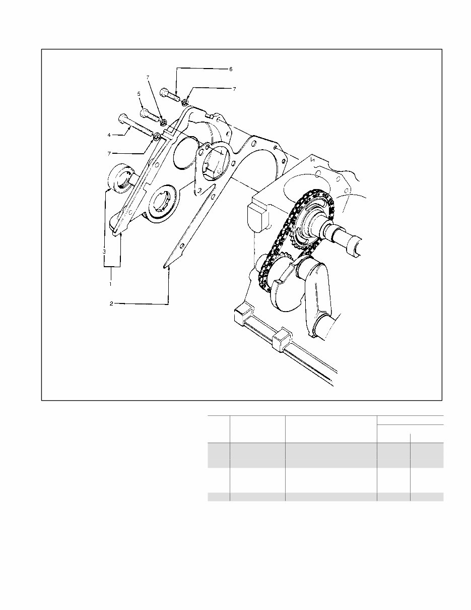
Group 4: Front Cover Assembly
Quantity
Variation Number
Item Part Number Description 1
1 224721 Cover and seal assembly 1
2 224722 Gasket, front cover 1
3 279111 Seal, front cover 1
4 # Bolt, M6 x 45 1
5 # Bolt, M6 x 40 3
6 # Bolt, M6 x 18 4
7 # Washer, split lock, B6 8
# Common hardware; procure locally.
8 TP-5413 5/01
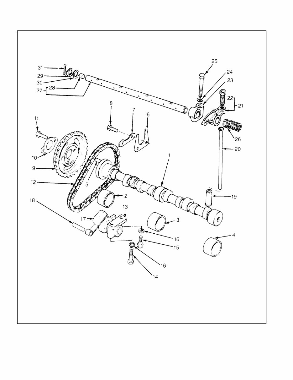
Group 5: Camshaft and Valve Control
You're Reading a Preview
What's Included?
Fast Download Speeds
Online & Offline Access
Access PDF Contents & Bookmarks
Full Search Facility
Print one or all pages of your manual
$27.99
Viewed 19 Times Today


Secure transaction
What's Included?
Fast Download Speeds
Online & Offline Access
Access PDF Contents & Bookmarks
Full Search Facility
Print one or all pages of your manual
$27.99
This manual provides detailed information on the parts of Kohler marine generators for the following models:
- 8C
- 8E
- 10C
- 10E
- 12.5C
- 12.5E
The manual includes an introduction, numbering system significance, illustrations, and guidance on finding part numbers and hardware references. It also features a specification number index for easy reference.
The parts are categorized into various groups, including:
- Group 1: Gaskets and Seals
- Group 2: Cylinder Block
- Group 3: Cylinder Head and Valves
- Group 4: Front Cover Assembly
- Group 5: Camshaft and Valve Control
- Group 6: Crankshaft and Piston
- Group 7: Flywheel and Clutch
- Group 8: Oil Pump and Pan
- Group 9: Fan and Water Pump
- Group 10: Intake Manifold
- Group 12: Ignition Module and Spark Plugs
- Group 101: Air Intake
- Group 103: Fuel System
- Group 104: Cooling System
- Group 105: Engine
- Group 107: Nameplate and Decals
- Group 108: Oil Pressure Switches
- Group 109: Skid and Plant Mounting
- Group 110: Water Temperature Switches
- Group 112: Starter
- Group 201: Generator and Mounting
- Group 301: Controller and Mounting
- Group 01: Literature
Additionally, the manual covers accessories and includes appendices for abbreviations, common hardware application guidelines, general torque specifications, hardware identification, and a common hardware list.


