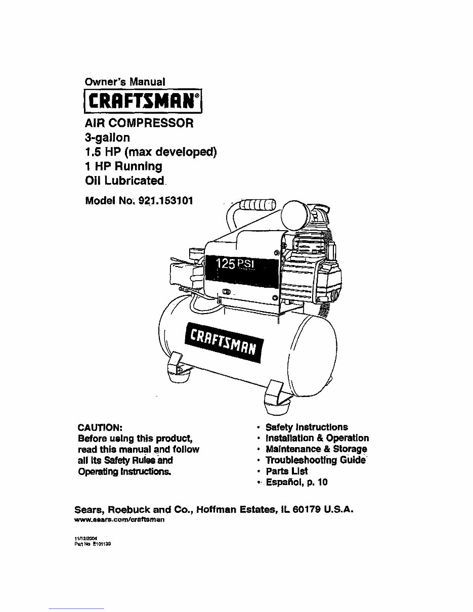
Owner's Manual AIR COMPRESSOR 3-gallon 1.5 HP (max developed) 1 HP Running Oil Lubricated Model No_ 921.153101 CAUTION: Before using this product, read this manual and follow all Its Safety Rules and Opera'dngInsUuc'dons. • Safety Instructions • Installation & Operation • Maintenance & Storag e • "rroubleshootlng Guide . Parts List • Espaflol, p. 10 Sears, Roebuck and Co., Hoffman Estates, IL 60179 U.S.A. www.sears.com/¢raftsman 11112Q004 P¢;1NO E10113G Downloaded from www.Manualslib.com manuals search engine
TABLE OF CONTENTS Page Warranty .................................................................................... see below Safety Instructions........................................................................ 1 Important Safety Instructions& Guldef=ne_ ......................................... 1 Spec_ffcabol18 ....................................................................................... 2 (31os._'y-. ....................................................................................... _ ...... 2 Duty Cycle .......................................................................................... 2 PaRs & Features ................................................................................... 3 Installarion & Assembly ........................................................................ 4 Opera, rig Procedures .............................................................................. 5 Maintenance ............................................................................................ 6 Storage ...................................................................................................... 6 TroubleehDoOngGuide ......................................................................... 7 Parts IJet .................................................................................................... 8 Espahol ..................................................................................................... 10 Serwce Number ......................................................................... back sever ONE YEAR FULL WARRANTY ON CRAFTSMAN AIR COMPRESSOR If this Craftsman Air Compressor fails due to manufacturer's defects in matertal or workmanship within one >,ear of Ihe date of purchase, RETURN IT TO THE NEAREST SEARS STORE OR SERVICE CENTER IN THE UNITED STATES and it _,1"11 be replaced or repaired (at our option), free of charge If this Air Compressor is used for commarolalor ramal purposes,this warrat_y applies for only 90 days from the data of purchase. This warranty gives you specific legal rights and you may 8]se have other rightswhich vary from state to stata Sears, Roebuck and Co., DepL B17WA, Hoffl_an Estates. IL 60178 Downloaded from www.Manualslib.com manuals search engine
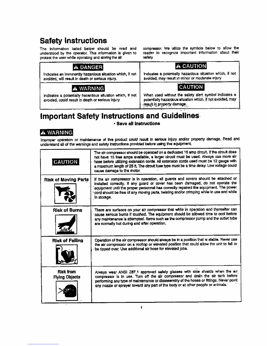
Safety Instructions The informatton hated below should be read and understood by the operator. Th=s mformation is given to _rote= the user while operatingand stodngthe air n.J[_:lll I Ilia, Indicatesanimmlnerltly hazardous situationwhip, h, if not avoided, willresultindeathor serious tnjury. ind|cstea • potentiallyhazardous situa'don which,if not e, volded,couldresultin death or serousinjury _ompmsSor. We utilize the symbols below to allow the reader to recogntza important information about their safety ]ndtcatesa potent=allyhazardous situation which, if not avoided, may result =n minor or moderate injury When used without the ssfaty start symbol indicates a potentiallyhazardous situation which, if not =,voided, may dam % = • Important Safety lnstructions and Guidelines • Save all Instructions V:_ _l_/-l=l_ll_[ll tmpmperoperat=on or maintenanceofthe=produd_couldresult in serious Injuryend/orpropertydamage.Read end understand ell of the warnings and safetyinstructions providedbeforeusing th_ equipment, Risk of Moving Part s Risk of Burns Risk of Falling Risk from Rylng Objects The air compressorshould be operated on • dedicated 15 amp €lmult. If the circuit does not have 15 flee _nps available, a larger circuit must be used. Always use more sir -hose before utilizing extension cords. AMexte_'_lencords used must be 12 gauge wi_ e maxtmum length of 25 P..The circuit fusetype must be e time delay. Low voltage could cause damage to the motor. If the sit €ompressor Is In operation, ell guards and covers should be attached or installed correctly, If any guard or cover has been damaged, do not operate the -equipment until the proper personnel has correctly repaired the aqulpmenL The power -cord should be flee of any moving ptrts, twisting andlor crimping while in use and while in ston_ge. There are surfaces on your air compressor that white in operation end thereafter can -cause serious burns If touched, The equipment should t_e allowed time to cool before any maintenance is attempted. Iterr_ such _ the compressor pump and the outlet tube are normallyhot during and after operttJon. Operation of the air compressor should always be in a position that ts at'J_la. Never use the air compressor on a rooftop or elevated position that could allow the unit to fell or -be tipped over. Use additional sit hose for elevated jobs. Alwayswear ANSI Z87,1 approvedsafetyglasseswith side shields when the air compressor is in use. Turn off the air compressor and drain the air tank before perfownlnganytypeof maintenance or disassembly ofthehosesorfittings,Never point any nozzleorsprayer toward any pe_lof the bodyor at other pop_pie or animals. r t Downloaded from www.Manualslib.com manuals search engine
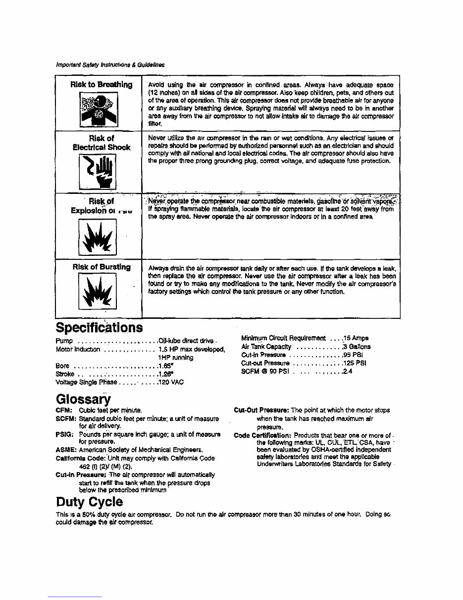
Important Safely Inslruel_On#& Guldellne_ Risk to Breathing Risk of Electrical Shock Risk of Exploslo_- oI r,,= Risk of Bursting Specdzcations Avoid using the air compresSOr in conked areas, Always have adequate space (12 Inshee) on aB sides of the air compressor.Also keep children, pats, and othersout of the area of operation. This air ¢ompmesor does not provide breathable air for anyone or any auxikary breathing device, _praying material will always need to be in another areaaway from the air compressorto not allow Intake air to damage the air compressor filter, Never utilize the a_r ooml_'eeasrin the tam or wet conditions.Any e|ectdcal issues or repairs should be performed by authorizedpemonnel such as on aiectT_cianand should oomp]ywith all national and local electrical codes. The air compressorshould also have the proper three prong groundingplug, correct voltage, and adequate _se protection. ;Ne._ operate the. compr_isor.neat oombusfible marshals,geeoUr_e01'e_oJ_nt-vapoFr_; If spraying flammable materials, locatethe sir compressor at least 20 teat-sway fro_ the spray areal Never operate the air compressor indoors or tn • confined area Alway=draintheair cempres=or tankdailyorafter eachuse.If the tankdevelopsa task, then replacethe air oompreasor. Neveruse the air compre_or after a leek has been foundorW to makeanymodificationsto thetank, Never modify the air compreesor's faotofysettingswhichcontrol the tankpressureoranyother function, Pump ...................... Oil-lube direct ddve- Motor Indu_on .............. 1.5 HP max developed, 1HP funning Bore ........................ 1.65w _roke ....... " .............. 1,26" Voltage Single Plisse ......... _120 VAC Minimum Circuit Requirement . ..._15 Ampe Air Tank Capac'W ............ .3 Ga,one Cut-in Pressure ............... 95 PSI Cut-out Pressure ........... ., .125 PSI SCFM @ 90 PSI ............ 2.4 Glossary CFM: Cubic feet per minute. SCFM: _'_dard cub_ r' feat per minute; a unitof measure for air delivetT. PSIG: Pounds per square Inch gauge: a unltof measure for pressure. ASME: American Soolety of Mechanical Engineer=. Catlfomla Code:Unlt may oomplywith California Code 462 (f) (2)/(M) (2). CuHn Pressure; -The air compressor will automatically start to refill the tank when the pressure drops below the pre._oribedminimum Duty Cycle Cut-Out Pressure: The pointat which the motor steps when the tank has reaohed maximum air pressure, Code Certification: Productsthat bear one or more of- the following marks: UL, CUL,ETLCSA, have - been evaluated by O_HA-certl_]edindependent safety laboratories and meet the applicable UnderwritersLabor_tariee Standards for Safety This Is a 50% dutycy_'ie air compressor.Donotruntheair €ompressor morethan 30 minutesof onehour.Doing coulddamagethe =lr compressor. Downloaded from www.Manualslib.com manuals search engine
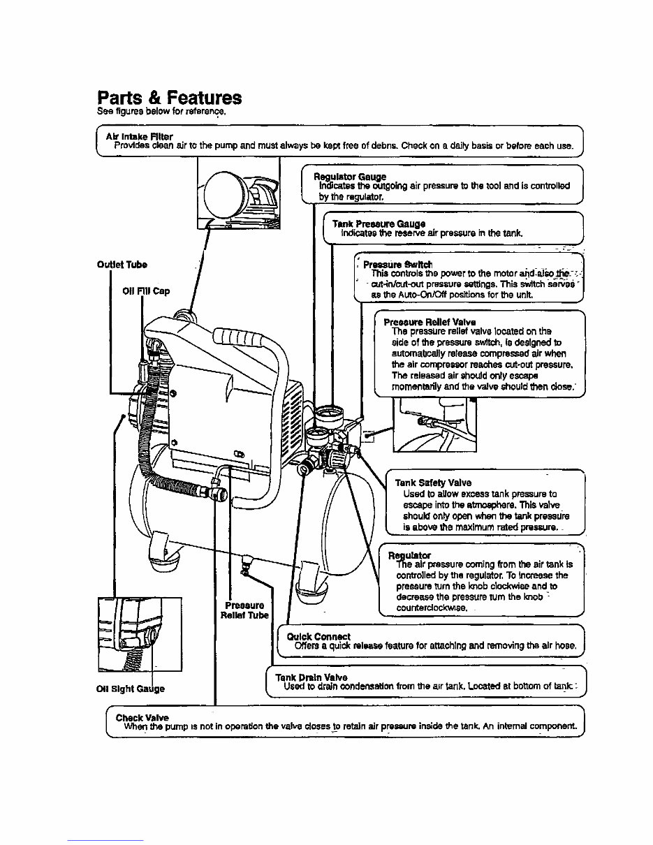
Parts & Features See figures below for reference, I AW Intake Rlter 1 Provides clean elf to the pump and must always be kept free of debris. Check on a daily basis or before each use. Outlet Tube on FillCap Regulator Gauge 1 Indicates the outgoing air pressure to the tool and is controlled by the regulator. Tank Preemui'eGauge | indicatesthe reserve air pressure in the tank. - _ 7- . Pressure 8wlt_ . . _ This controlsthe power to the motor aJ_d.al_e.--'.:_ cut4n/cut-out pressure settings. This switch .served "1 the AkRo-OniOffpositionsfor the unit, J = Valve The pressure relief valve located on the side of the pressure switch, is designed to automa,bcally release compressed air when the air compressor reaches cut-out pressure, The released air shouJd only escape momentarily and the valve should then dose. t Valve Used to allow excess tank pressure to e_pe into the atmosphere, This valve should only open when the tank preastJre is above the maximum rated pressure. Regutatcr '_ The air pressure coming from the air tank is | con_olled by the regulator, To increasu the | pressure turn the le_ob clePJxwiee and to | decrease the pressure turn the knob _ | Pressure counterdockw;su. J Relief Tube Quick Connect 1 Offers • quick release feature for sttashtng and removing the air hose, l Tank DraIn Valve 1 011Sight Gatiga Used to drsJn oundensation from the a=rtank, Located st bottom of tank.: I Check valv_ 1 When the pump is not in operation the valve €losests retzdn =drpressure in,;de the tank, An internal component. Downloaded from www.Manualslib.com manuals search engine
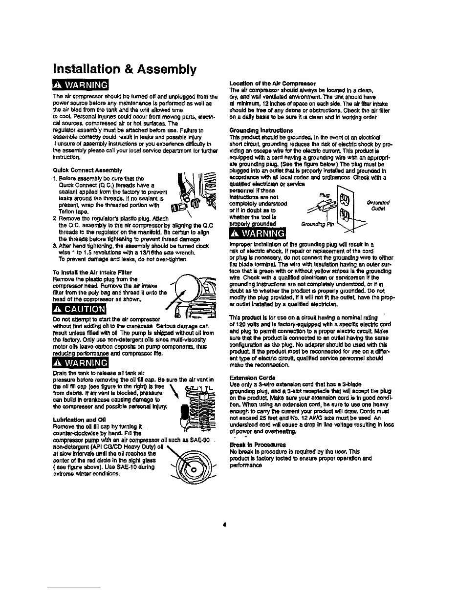
Installation & Assembly The air compressor should be turned off and unptuggod Imm the power coume betore any rnainrananoe is performed as well a= the air bled from the tank and the unit allowed t_rne to cool. Personal Inlunes could oOcvr from moving paris, elecld- col sources, compressed elf or hot surfaces. The mgulutor assembly must be a_eched before use, Failure to assemble correctly could result in lo_s end poss=bleinjury It unsure of assembly instructions or you expe(_ence diffisul_ in the assmmb;y please call your local .service deparlmem Ior forthsr Instruction, Qufok Connect Assembly 'L Before assembly be sure that the Quick Connect (Q C,) threads have a sealant applied from the factory m proven! Iaa_ around the threads. If no sealant is present, wrap [ha threaded portion W_l Teflon tope. 2 Remove the regulator's plasito plug, Attach the O C. assembly to the air compressor by aligning the Q,C threads to the regulator on the manifold. Be certam ld align the threads before tlghtenleg to prevent thread damage 3, After hand t_htening, the a_embly should be turned clock wise 1 to 1,5 revolmlona with • 13ki6ths _ze wrench. To prevent damage and leaks, do not over-tighten To ths'taU the Air Intake Rlter Remove the pleatlo plug from the _,/_ _"-'_ compressor head. Remove the air into, he "_( _'_ t]ifer from the poly bag and thread it onto the t_' j_ asr as shown. Do not otternptto start the =drcomprasecr without ffrst adding oil to the crankcase Serious damage can resuit unl_ fifled _th oil The pump Is shipped without ell from the fectury.Only use non.detergent clio since multl-vlecos W motor oils leave carbon itapos_ on pump ¢omp0nsms, thus and compressor rife, Drain the tank to I_leece all tank air pressure betom removthg the oll _ P._p, Be sure the air vent in the 09 fill cap (see figure to the right) ;8 free _ L_.,7_I ?L from debris. If ntr vent Is blocked, pressure can build In orankcase causing dam N to lee compressor and possPblo pereonat in_Jry. Lubdeatton and Oil Remove the oll tiffcap by turning it counter-clockwise by hand. Fd] the compressor pump v/_h an sir €ompressor ell such as SAF.-_0 non.detergent (API CG/CD Heevy Duty) oll at slow thterv_ unlll the oil tee0hea the eentor of the red oirelo In the sight itiass ( see figure above). Use SAE-10 during extreme winter ¢onditfono. Lo_-'Mlon of the Air Compmuor The air compressor should oiwe.ys be Io_ted In n clean, dry. and welt verdllated environment. The unit should have ai mNmum, 12 Inchec of space on each side, The air m_ar intake should be _ee of any debris or obstmc_ono, Check the air fi_tor on a dally bogle to be sure _tis clean and in working order Grounding Inatru_lone TI_ product should be greund_. In the event of an decuir.al sherl oh'cult, grounding reduses I_ risk of electric r.hock by pro- vlrflngan escape wire for the eleclnfocurrant,This product is equipped with • cord having o grounding wire with an agproprf- ato gmun_ng plug. (See the figure below) The plug must be plugged into an outlet that is properly installed and grounded In acmrdanco wi_ ag lOcal codas and ordinances Check with a quaiiflod olec_ln_n or sense personnel ff these ins'b'ucfions arenot P/ug complet$1y understood Omunde_ or If in doubt as to guilt whether the tool is Ground/no P/n Improper install_on of the grounding p_ugwill result In It risk of slocMe shock. IFrepair or replecomerd of the cord or p_ugIs nuseseery, do not conne_ the grounding w_rsto either fiat blade fermlnaL The wire wi_ insula_on having an outer sur- face tha_ Is green with or without yellow stripe= Is _ grounding wire CheeX _ a quaiffled ethetri=an or serviceman If the grounding ii%=d_.,ctin_are not completely understood, or if m doubt as to _i_uther the product m propedy grounded. DO not modify the plug provided, If Itwill not th the oubeL havE)the prop er ou'Jetinstalled by & qualified aiesfi'idan. This pmduut Is for use on ,= cimuit having a nominal rot_ng of 120 wits and is lectory-equltwed with e spa€tits aie_dc cord und plug to pem_]t conno_lOn to a proper electric clrcolL Make sure that the product Is connected to as outbt hav_g the same sunfigur_gon as the plug, No adapter should be used with this product, Htheproduct mutd be reconnected for use on a differ- ent type of eb¢_e circuit, quailfled servlse personnel should mske ths reconn_fion, ExtensionCords Useonlya 3-wire extensioncord met has e 3..blade grounding plug.and a S-slot nmsptanlo that willacceptthe plug onl_e predu_ Ma_e sumyoursxtanaloncordis Ingoodcondi- Ifon, When using an extanaioncord,be suretouaeone heavy onDugh to P.art_ the currentyourproduut will draw. Cordsmust not escoed 25 feet and No. 12 AWGsee must be ungd An undersized cord willceu.'u= a drop in linevoltage resulting In loss el power and overileetthg, BrenkIn Prooedure_ NobreakIn pro_dom is required by the usur,Trde productIsfactorylect_toensureproperoperationand performanse Downloaded from www.Manualslib.com manuals search engine
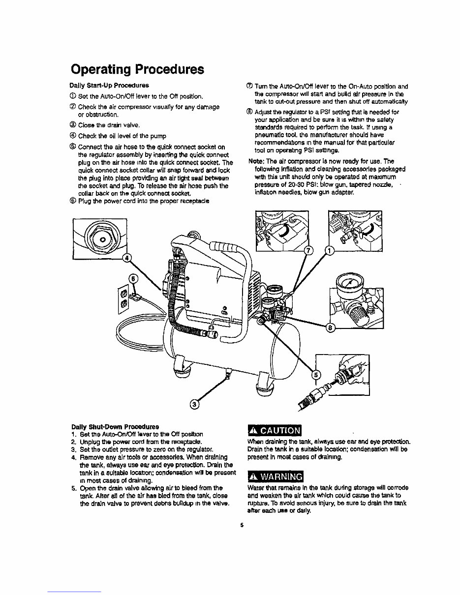
Operating Procedures Daily Start-Up Procedures O Set the Auto-On/Off lever to the Off position. __ Check the air compressor visuallyfor any damage or obstru_on, _) Close the drain valve. Check the oil level of the pump Connect the air hose to the quick connectsocket on the regulator assembly by ineerling the quick connect plug on the air hose rote the quickconnect soci<at,The quick connect socket collar will snap forward and lock the plug into piece providingan airtight ssai between =hesocket and plug, To relez_e the air hose pushthe collar back on the quick connect socket. _) Plug the power cord into the proper receptacle _/_Turn the Auto-On/off lever to the On-Auto position and =he compressor v_llstart and build air pressure in the tank to out-outpressure and then shut off automatically Ad}ust the regula_r to a PSI se_lngthat Is needed for your applica_on and be sure it ts withm the safety standards required to performthe task. ff using a pneumatic tool, the manufacturer should have recommendatJons =n the manual for that particular tool on eperabng PSI se_ngs. Note: The air compressor is now ready for use. The following Inflationand cleaning aosessorlea packaged v_ththis unit should only be operated at maximum pres_Jre of 20-30 PSI: blow gun, tapered nozzle, infla_on needles, blew gun adapter. Dally Shut-Down Prooeduma 1. Set the Auto-On/Off laver to the Off posihan 2. Unplug the power cord from the receptacle. 3. Set the outlet pressure to zero on the regulator, 4. Remove any air tools or accessories, When draining the tank, always use e_r and eye profectten. Drain the tank in a suitable location;condensation will be present =nmost cassa of draimng. 5. Open the drain valve allowing airto bleed fl'omthe tank. After 811ofthe air has bled from the tank, close the drain valve to prevent debns buildup =nthe valve. P"REo,_r,,_llJ]l[o_ When drainingthe tank, always use ear and eye protection. Drain the tank in a suitable location; condensation will be present In most cases of dreinmg, Water that remains in the tank dudng storage will corrode and weaken the air tank which couldcause the tank to rupture.To Avoid serious injury, be sure to drain the tank after each usa or dady. S Downloaded from www.Manualslib.com manuals search engine
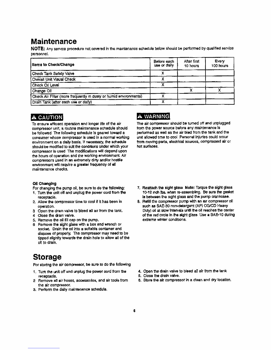
Maintenance NOTE: Any service procedure not covered in the maintenance schedule below should be performed by qualified service _ereoenet. Items to Check/Change Check Tank Safety Valve Overall Unit Visual Check Check Oil Level Change Oil Check Air RIter (more frequently =ndusty or humid environments) Drain Tank (after each use or daily) Before each use or daily X X X X X Afterfirst lO hours X Every 100 hours z Irc tlji R To ensure efficient operation and longer life of the air compressor unit, a routine maintenance schedule should be followed The following schedule is geared toward • consumer whose compressor Is used in a normal working environment on a daily basis. If necessary,the schedule should be modified TO suit the condrl_ansunder whichyour compressor is used The modifications wiltdepend upon the hours of operation and the working environment. Air compressors used in an extremely difo/end/or hostile environment will require a greater frequency of ell maintenance checks, The air compressor should be turned off and unplugged from the power source before any maintenance is performed as well as the alr bled from the tank and the unit aTIowedt=meto cool Psrscna! injuries could occur from moving parts, electrical scum.s, compressed air or hot surfa_J. Oil Changing For changing _e pump oil. be sure to do thefollowing: t, Turn the unit off and unplug the power cord from the receptacle. 2. Allow the compressor tLmato cool if It has bean in opera'0on. 3 Open the dra=nvalve to bleed all air from the tank. 4 Close the dram valve. 5. Remove the oil I_11 cap on the pump. 6 Remove the sight glass with e box end wrench or socket. Drain the oil Into a suitable sentaJner and dispose of properly. The compressor may need to be tipped slightly towards the drain hole to allow all of the oll to drain. 7. Reattaoh the sight glass Note: Torque the sight glass 10-12 inchll_, when re-assembling. Be sure the gasket is betwsen the s_ght glass and the pump crankcase, 8, Refill the compressor pump with an _ur compressor all such as SAE-30 non-detergent (APt CG/CD Heavy Duty) oil a_slow _ntervais ur_l the o'dreaches the center of the red orcle in the sight glass Use a SAE-t0 during extreme winter conditions, Storage For stodng the air compressor, be sure to do the fotlowing 1, Turn the unit off and unplug the power cord from the receptacle. 2 Remove all air hoses, accessories, and air tools from the air compressor. 3. Perform the daily maintenance schedule, 4. Open the drain valve to bleed all air from the tank 5. Close the drain valve. 6. Store the air compressor in a clean and dry location. Downloaded from www.Manualslib.com manuals search engine
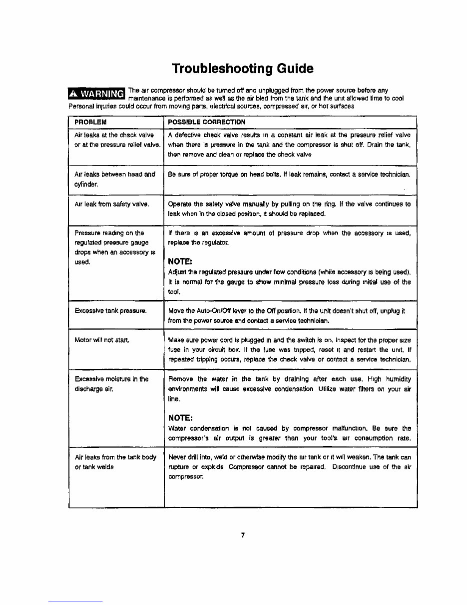
Troubleshooting Guide _The air compressor should be turned off and unplugged from the power source before any mamtenanse is performed as well as the _Jr bted from the tank and the unut allowed time to cool Persona] inluries could occur from moving pans, _[ectrica] sources, compressed anr,or hot surfaces PROBLEM POSglBLE CORRECTION Air leaks at the check valve A defective chsok valve results in s constant air leak at the pressure relief valve or st the pressure relief valve, when there is pressure in the tank and the compressor is shut off. Drain the tank, then remove and clean or replace the check valve Air leaks between head and Be sum of proper torque on head bolts. If leak rem,_ins,contact a servicetsohnician. cylinder. Anrleek from safety valve. Operate the safety valve manually by pulling on the dng, If the valve continues to leak when in the closed posibon, tt should be replaced. Pressure msding on the regulated pressure gauge dreps whenanecoeseory_e used. Excessive tank pressure. Motor will not e_aR, Excessive moisture _rt the discharge sir. Air leaks from the tank body ortank welds If there us an excessive amount of pressure drop when the accessory ns used, replase the regulator. NOTE: Adjust the regulated pressure under flow conditions(while accessory is being used). It is normal for the gauge to show minimal pressure loss dudng _niUal use of the tool, Move the Auto-On/Off lever to the Off position. If the unit doesn't shut off, unplug it from the power source end contact a service technician, Make sure power cord is plugged In and the switch is on. inspect for the proper size rues in your circuit box. If the fuse was tnpped, reset Pl and restart the unnt. If repeated tripping occurs, replace the check valve or contact a service technician, Remove the water in the tank by draining after each usa. High humidity environments will cause excessive condensation Utilize water/llter_ on your air line. NOTE: Water condensationis not caused by compressorma]functnon. Be sure the compreseor's slr output is greater then your tool's anr coneumptfonrate. Never drill into, weld or otherwise modify the air tank or it wnllweaken, The tank can rupture or explode Compressor cannot be re_nred, DIscontfnue use of the air compressor, Downloaded from www.Manualslib.com manuals search engine
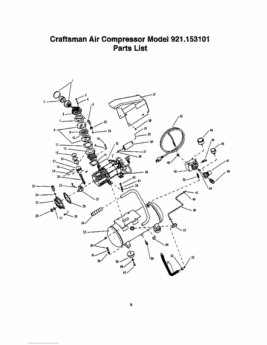
Craftsman Air Compressor Model 921.153101 Parts List 25i I Downloaded from www.Manualslib.com manuals search engine
The Craftsman 1HP 3-Gallon Oil Lubricated Air Compressor (Model 921.15310) Owners Manual is a comprehensive guide designed for owners of this specific Craftsman air compressor model. It details essential information for the proper operation, maintenance, and troubleshooting of the compressor. The manual outlines safety precautions, setup instructions, and guidelines for using the compressor effectively. It also provides maintenance tips to ensure long-lasting performance, including oil level checks, filter replacements, and proper storage practices.
The troubleshooting section assists in identifying and solving common issues, ensuring minimal downtime. With clear diagrams and step-by-step instructions, this manual is vital for maximizing the efficiency and lifespan of your Craftsman 1HP 3-Gallon Oil Lubricated Air Compressor, making it an indispensable resource for both novice and experienced users.
Printable: Yes
Language: English
Compatibility: Pretty much any electronic device, incl. PC & Mac computers, Android and Apple smartphones & tablet, etc.