

STIHL 045 & 056 CHAIN SAWS Full Service & Repair Manual
What's Included?
Fast Download Speeds
Online & Offline Access
Access PDF Contents & Bookmarks
Full Search Facility
Print one or all pages of your manual
~
••
.~
~
4)
SERVICE MANUAL
STIHL 045,056
FOREWORD
This Service Manual covers model
045 chain saws up to machine number
5 919 430 as well as later machines
unless technical information bulletins
have been issued in the meantime
with updated repair procedures.
Model 045 have substantially the
same constructional features as
model 056 chain saws. This Service
Manual can therefore be used for the
056 chain saws as well.
In the event of faults it is quite pos-
sible that a single fault may have
several causes. It is therefore ad-
visable to consult the "Trouble-
shooting Chart" in each chapter when
tracing faults. We also recommend
that you make use of the exploded
views in the illustrated parts lists when
carrying out repair work.
This service manual and all technical
information bulletins are intended ex-
clusively for the use of STI HL servicing
dealers and staff and must not be
passed on to third parties.
Andreas Stihl
Postfach 1760
D-7050 Waiblingen
CONTENTS
Specifications
Saw Chain Drive with Clutch
Saw chain drive with clutch,
trouble shooting, disassembly
and repair
Driving Parts
Crankshaft with connecting
rod, cylinder and piston, ex-
posing the cylinder, removing
cylinder and piston, crank-
shaft and crankcase pressure
testing
Ignition System
Flywheel Magneto
Function, spark plug, high ten-
sion lead, short-circuit wire
and stop switch, checking and
adjusting the ignition timing,
flywheel, stator plate, ex-
changing the breaker point
set, ignition coil, condenser,
trouble shooting
Ignition System
Electronic Ignition
Advantages and function, con-
trolling the function of the elec-
tronic system on the motor-
checking and adjusting the
ignition timing - removal of
trigger plate - repair of the
electronic - trouble shooting
Rewind Starter
Design and operation - dis-
assembly and repair - instal-
lation of a new starter rope -
installation of rewind spring -
2 tensioning the rewind spring -
general repair
5
AV-Handle System
Disassembly and repair
Oil Pump
8 Operation - oil quantity con-
trol-removal of oil pump -
repair
Carburetor set-up and
Air Filter
Design and operation - dis-
assembly of carburetor and
elbow connector - repairing
16 component parts - carburetor
adjustment - pressure testing
Fuel Tank and Fuel Feed
Throttle Control
Special Tools
28
32
1
35
36'
38
44
45
46
2
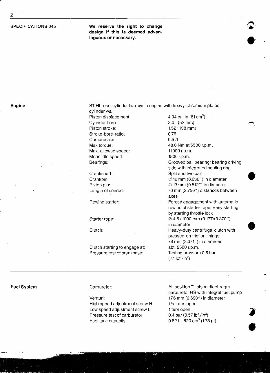
SPECIFICATIONS 045
We reserve the right to change
design if this is deemed advan-
tageous or necessary.
4.94 cu. in (81 cm3)
2.0" (52 mm)
1.52" (38 mm)
0.76
9.5 :1
48.6 Nm at 5500 r.p.m.
11000 r.p.m.
1800 r.p.m.
Grooved ball bearing; bearing driving
side with integrated sealing ring
Split and two part
o 16 mm (0.630Jl) in diameter
o 13 mm (0.512") in diameter
70 mm (2.756") distances between
axes
Forced engagement with automatic
rewind of starter rope. Easy starting
by starting throttle lock
o 4.5x1000 mm (0.177x9.370")
in diameter
Heavy-duty centrifugal clutch with
pressed-on friction linings,
78 mm (3.071") in diameter
abt. 2500 r.p.m.
Testing pressure 0.5 bar
(7.1Ibf./in2)
Starter rope:
Rewind starter:
Clutch starting to engage at:
Pressure test of crankcase:
Clutch:
Crankshaft:
Crankpin:
Piston pin:
Length of conrod:
STIHL-one-cylinder two-cycle engine with heavy-chromium plated
cylinder wall
Piston displacement:
Cylinder bore:
Piston stroke:
Stroke-bore-ratio:
Compression:
Max torque:
Max. allowed speed:
Mean idle speed:
Bearings:
Engine
Fuel System
Carburetor:
Venturi:
High speed adjustment screw H:
Low speed adjustment screw L:
Press.ure test of carburetor:
Fuel tank capacity:
All position Tillotson diaphragm
carburetor HS with integral fuel pump
17.6 mm (0.693") in diameter
11/4turns open
1 turn open
0.4 bar (0.57 Ibf./in2)
0.821- 820 cm3 (1.73 pt)
1)
. .-
~J
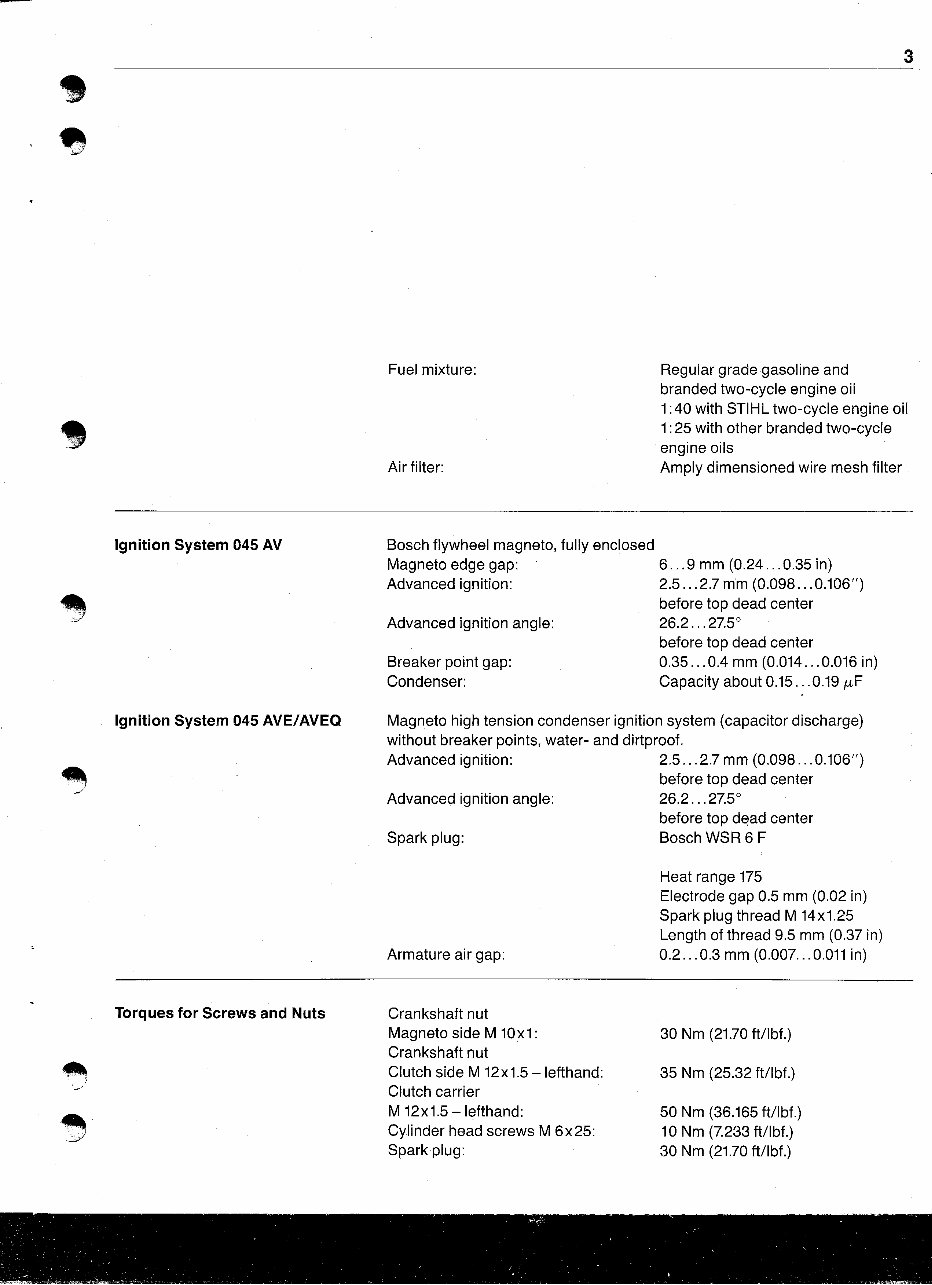
Fuel mixture:
Air filter:
3
Regular grade gasoline and
branded two-cycle engine oil
1:40 with STIHL two-cycle engine oil
1:25 with other branded two-cycle
engine oils
Amply dimensioned wire mesh filter
Advanced ignition angle:
Breaker point gap:
Condenser:
Ignition System 045 AV
Ignition System 045 AVE/AVEQ
Bosch flywheel magneto, fully enclosed
Magneto edge gap: 6 9 mm (0.24 ... 0.35 in)
Advanced ignition: 2.5 2.7 mm (0.098 ... 0.106")
before top dead center
26.2 ... 27.50
before top dead center
0.35 ... 0.4 mm (0.014 0.016 in)
Capacity about 0.15 0.19 fLF
Magneto high tension condenser ignition system (capacitor discharge)
without breaker points, water- and dirtproof.
Advanced ignition: 2.5 ... 2.7 mm (0.098 ... 0.106")
before top dead center
Advanced ignition angle: 26.2 ... 27S
before top d~ad center
Spark plug: Bosch WSR 6 F
~
.-/
Torques for Screws and Nuts
Armature air gap:
Crankshaft nut
Magneto side M 10x1:
Crankshaft nut
Clutch side M 12x1.5 -Iefthand:
Clutch carrier
M 12x1.5 -Iefthand:
Cylinder head screws M 6x25:
Spark plug:
Heat range 175
Electrode gap 0.5 mm (0.02 in)
Spark plug thread M 14x1.25
Length of thread 9.5 mm (0.37 in)
0.2 ... 0.3 mm (0.007. .. 0.011 in)
30 Nm (21.70 ftllbf.)
35 Nm (25.32 ft/lbf.)
50 Nm (36.165 ftllbf.)
10 Nm (7.233 ft/lbf.)
30 Nm (21.70 ftllbf.)
4
Cutting Attachment
Guide bars:
Bar lengths:
Oilomatic-chains:
Chain speed:
Chain lubrication:
Maximum oil output:
Minimum oil output:
Mean oil output:
Oil tank capacity:
Chain sprocket:
STIHL Duromatic bar with carbide
tipped nose; STIHL Rollomatic bar
with spider nose. Either type is
protected from corrosion by
induction-hardened contact surfaces
Duromatic 40, 45, 50 and 63 cm
(16, 18, 20 and 25")
Rollomatic 37, 40, 45, 50 and 63 cm
(15,16, 18, 20 and 25")
9.32 mm (3fa")-Rapid and -Topic
10.26 mm (0.404")-Rapid
17.4 m/sec. (57.1ft per second)
at 8000 r.p.m. with 3/8" chain
19.2 m/sec. (63 ft per second)
at 8000 r.p.m. with 0.404" chain
Fully automatic oil pump with pump
plunger, output depending on chain
speed, pump supplying oil only
when chain is running, additional
quantity control by adjusting control
bolt.
15 cm3/min. (0.92 cu. in per minute)
at 6000 r.p.m.
8.5 cm3/min. (0.52 cu. in per minute)
at 6000 r.p.m.
12 cm3/min. (0.73 cu. in per minute)
at 6000 r.p.m.
0.36 I = 360 cm3 (0.76 pt)
7 teeth
Weights Motor dry
without bar and chain:
with 37 cm (15") bar and chain:
AViAVE:
7.9 kg (17.4 Ib)
9.1 kg (20.1Ib)
AVEQ:
8.3 kg (18.3 Ib)
9.5 kg (20.9 Ib)
Extras
STIHL repair kit (set of the most common wearing parts)
for friction shoe rewind starter 1115 900 5000
for single pawl rewind starter 1115 900 5001
Set of gaskets 1115 007 1050
e SAW CHAIN DRIVE AND CLUTCH
~
~
The power from the engine is trans-
mitted to the saw chain by a centri-
fugal clutch. This clutch is composed
of clutch carrier, clutch shoes and
clutch springs. But the two washers
in front of and behind the clutch as
well as the chain sprocket with
clutch drum riveted onto it are also
needed for a proper operation of
the clutch.
With increasing speed the clutch
shoes, held by the clutch springs,
Troubles
Bad engagement, clutch slips,
chain does not rotate
are forced to the outside; they are
pressed against the clutch drum
which is connected with the chain
sprocket thus transmitting the
engine power to the chain sprocket
and the saw chain.
The clutch springs have a certain
pre-tension so that clutch will not
engage before the engine speed of
about 2500 r.p.m. is reached. The
carburetor has to be adjusted in
such a way (see paragraph carbure-
Causes
Clutch linings worn
5
tor adjustment) that the chain does
not rotate at idle speed.
The clutch of the STIHL 045 AV and
045 AV electronic needs almost no
maintenance at all but, of course,
normal wear cannot be avoided.
Therefore, the clutch and the chain
sprocket must be checked on proper
condition periodically.
How to correct
Replace the complete set of clutch
shoes
Clutch and chain sprocket dirty (oil) Wash in clean gasoline, roughen
clutch linings with emery cloth
~
;.//
Saw chain does not stop running
when idling, extraneous noises
No chain lubrication
Extreme chain wear
Engine speed too high when idling
Spring stretched or fatigued
Spring hooks damaged
Needle cage damaged
Drive pin of cover plate broken
Worn chain sprocket
Readjust idle adjustment screw
Replace all springs
Replace needle cage
Install new cover plate
Replace chain sprocket
6
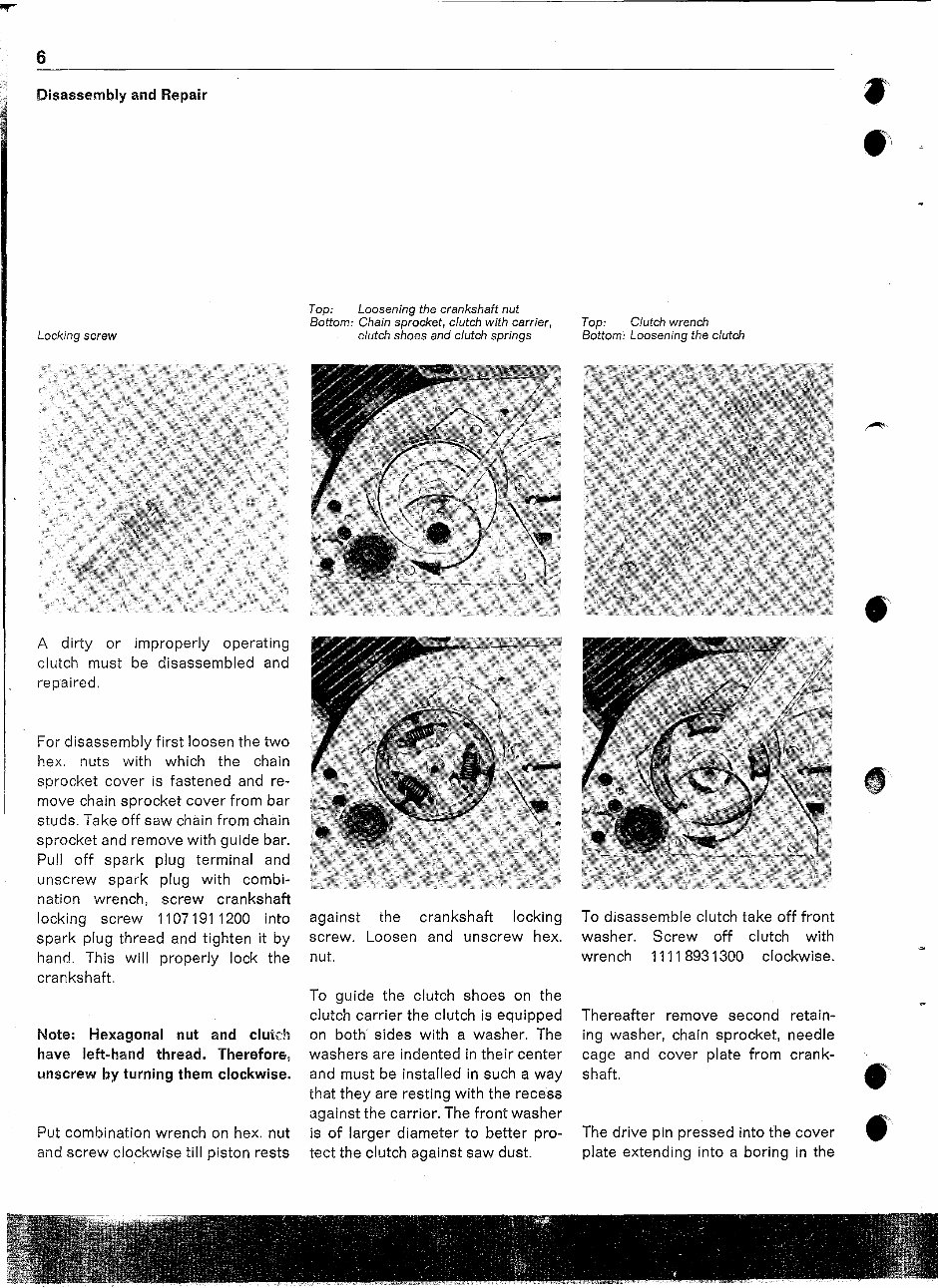
Disassembly and Repair
Locking screw
A dirty or improperly operating
clutch must be disassembled and
repaired.
For disassembly first loosen the two
hex. nuts with which the chain
sprocket cover is fastened and re-
move chain sprocket cover from bar
studs. Take off saw chain from chain
sprocket and remove with guide bar.
Pull off spark plug terminal and
unscrew spark plug with combi-
nation wrench, screw crankshaft
locking screw 11071911200 into
spark plug thread and tighten it by
hand. This will properly lock the
crankshaft.
Note: Hexagonal nut and clutch
have left-hand thread. Therefore,
unscrew by turning them clockwise.
Put combination wrench on hex. nut
and screw clockwise till piston rests
Top: Loosening the crankshaft nut
Bottom: Chain sprocket, ciutch with carrier,
clutch shoes and clutch springs
against the crankshaft locking
screw. Loosen and unscrew hex.
nut.
To guide the clutch shoes on the
clutch carrier the clutch is equipped
on both sides with a washer. The
washers are indented in their center
and must be installed in such a way
that they are resting with the recess
against the carrier. The front washer
is of larger diameter to better pro-
tect the clutch against saw dust.
Top: Clutch wrench
Bottom: Loosening the ciutch
To disassemble clutch take off front
washer. Screw off clutch with
wrench 11118931300 clockwise.
Thereafter remove second retain-
ing washer, chain sprocket, needle
cage and cover plate from crank-
shaft.
The drive pin pressed into the cover
plate extending into a boring in the
~
.~
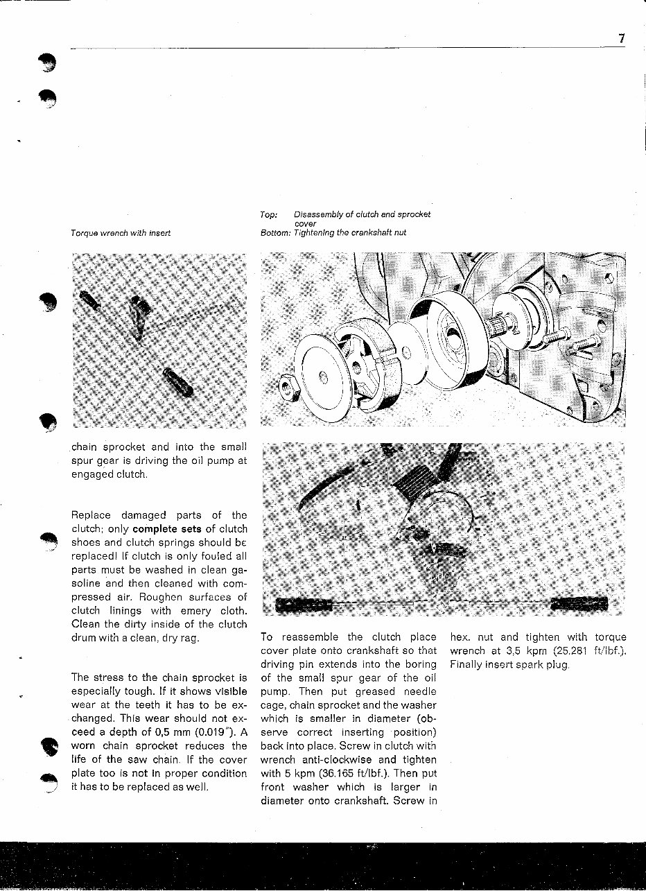
Torque wrench with insert
Top: Disassembly of clutch and sprocket
cover
Bottom: Tightening the crankshaft nut
7
~
;;/
chain sprocket and into the small
spur g~ar is driving the oil pump at
engaged clutch.
Replace damaged parts of the
clutch; only complete sets of clutch
shoes and clutch springs should bE:
replaced! If clutch is only fouled all
parts must be washed in clean ga-
soline and then cleaned with com-
pressed air. Roughen surfaces of
clutch linings with emery cloth.
Clean the dirty inside of the clutch
drum with a clean, dry rag.
The stress to the chain sprocket is
especially tough. If it shows visible
wear at the teeth it has to be ex-
.changed. This wear should not ex-
ceed a depth of 0,5 mm (0.019"). A
worn chain sprocket reduces the
life of the saw chain. If the cover
plate too is not in proper condition
it has to be replaced as well.
To reassemble the clutch place
cover plate onto crankshaft so that
driving pin extends into the boring
of the small spur gear of the oil
pump. Then put greased needle
cage, chain sprocket and the washer
which is smaller in diameter (ob-
serve correct inserting position)
back into place. Screw in clutch with
wrench anti-clockwise and tighten
with 5 kpm (36.165 ft/lbf.). Then put
front washer which is larger in
diameter onto crankshaft. Screw in
hex. nut and tighten with torque
wrench at 3,5 kpm (25,281 ft/lbf.).
Finally insert spark plug.
8
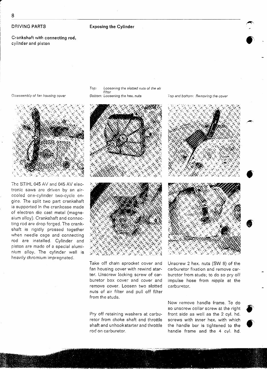
DRIVING PARTS
Crankshaft with connecting rod,
cylinder and piston
Disassembly of fan housing cover
Exposing the Cylinder
Top: Loosening the slotted nuts of the air
filter
Bottom: Loosening the hex. nuts Top and bottom: Removing the cover
The STIHL 045 AV and 045 AV elec-
tronic saws are driven by an air-
cooled one-cylinder two-cycle en-
gine. The split two part crankshaft
is supported in the crankcase made
of electron die cast metal (magne-
sium alloy). Crankshaft and connec-
ting rod are drop forged. The crank-
shaft is rigidly pressed together
when needle cage and connecting
rod are installed. Cylinder and
piston are made of a special alumi-
nium alloy. The cylinder wall is
heavily chromium impregnated.
Take off chain sprocket cover and
fan housing cover with rewind star-
ter. Unscrew locking screw of car-
buretor box cover and cover and
remove cover. Loosen two slotted
nuts of air filter and pull off filter
from the studs.
Pry off retaining washers at carbu-
retor from choke shaft and throttle
shaft and unhookstarter and throttle
rod on carburetor.
Unscrew 2 hex. nuts (SW 8) of the
carburetor fixation and remove car-
buretor from studs; to do so pry off
impulse hose from nipple at the
carbur8tor.
Now remove handle frame. To do
so unscrew collar screw at the right
front side as well as the 2 cyl. hd.
screws with inner hex. with which
the handle bar is tightened to the
handle frame and the 4 cyl. hd.
-'
~.
.-
;
,.--/
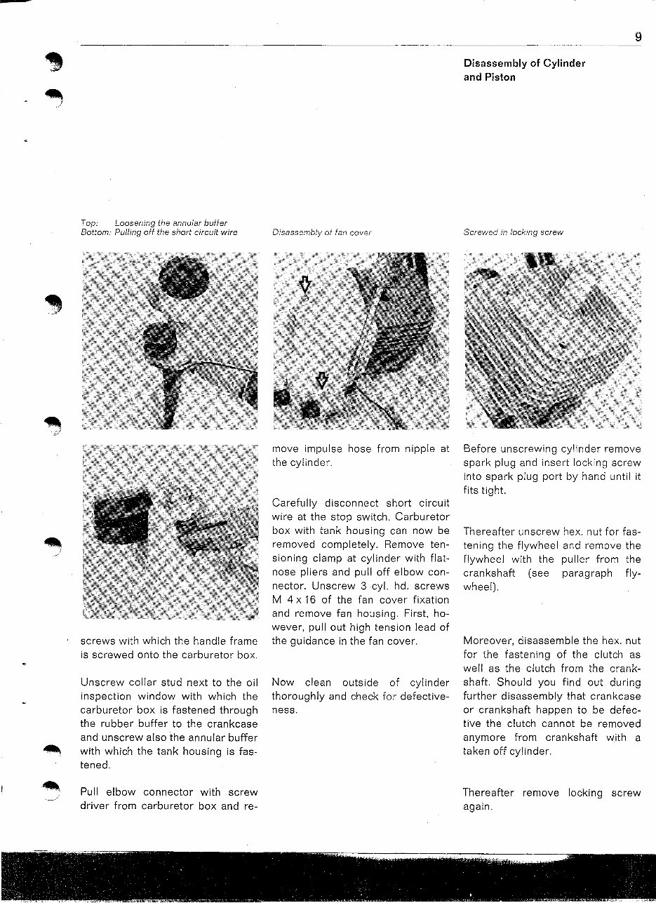
Top: Loosening the annular buffer
Bottom: Pulling off the short circuit wire
screws with which the handle frame
is screwed onto the carburetor box.
Unscrew collar stud next to the oil
inspection window with which the
carburetor box is fastened through
the rubber buffer to the crankcase
and unscrew also the annular buffer
with which the tank housing is fas-
tened.
Pull elbow connector with screw
driver from carburetor box and re-
Disassembly of fan cover
move impulse hose from nipple at
the cylinder.
Carefully disconnect short circuit
wire at the stop switch. Carburetor
box with tank housing can now be
removed completely. Remove ten-
sioning clamp at cylinder with flat-
nose pliers and pull off elbow con-
nector. Unscrew 3 cyl. hd. screws
M 4 x 16 of the fan cover fixation
and remove fan housing. First, ho-
wever, pullout high tension lead of
the guidance in the fan cover.
Now clean outside of cylinder
thoroughly and check for defective-
ness.
9
Disassembly of Cylinder
and Piston
Screwed in locking screw
Before unscrewing cylinder remove
spark plug and insert locking screw
into spark plug port by hand until it
fits tight.
Thereafter unscrew hex. nut for fas-
tening the flywheel and remove the
flywheel with the puller from the
crankshaft (see paragraph fly-
wheel).
Moreover, disassemble the hex. nut
for the fastening of the clutch as
well as the clutch from the crank-
shaft. Should you find out during
further disassembly that crankcase
or crankshaft happen to be defec-
tive the clutch cannot be removed
anymore from crankshaft with a
taken off cylinder.
Thereafter remove locking screw
again.
You're Reading a Preview
What's Included?
Fast Download Speeds
Online & Offline Access
Access PDF Contents & Bookmarks
Full Search Facility
Print one or all pages of your manual
$31.99
Viewed 23 Times Today


Secure transaction
What's Included?
Fast Download Speeds
Online & Offline Access
Access PDF Contents & Bookmarks
Full Search Facility
Print one or all pages of your manual
$31.99
Get instant access to the Complete Factory Service Repair Workshop Manual without any extra fees or expiry dates. This Professional Manual is suitable for both professional Mechanics and DIY enthusiasts, covering all repairs, servicing, and troubleshooting procedures with step-by-step instructions, detailed photos, diagrams, and highly detailed exploded diagrams & pictures.
Print out a single page or the entire manual as per your choice. The Manual can be used on multiple computers without any limitations or trial periods and can be used for life without the need to renew or pay any extra. It is fully compatible with all Windows & MAC Computers.
Click the button to get your hands on this comprehensive manual.


