

Stihl 015 015L Chainsaw Service Repair Workshop Manual
What's Included?
Fast Download Speeds
Online & Offline Access
Access PDF Contents & Bookmarks
Full Search Facility
Print one or all pages of your manual
T-
i
.c
STTHL AI5
ti}
C
o
PREFACE
The
power
cirain saws STIHL 015
and015L havebeenfirst introduced
at the beginning of July 1973. This
service shop manual is ment to
serve you as a guide book for pro-
per and skilled repair works on both
of thesemachines.
Moreover,we suggest to use the
illustrated spare parts list in our
instruction manuals as a help when
repairing. Technical modifications
which should be necessary after
publication of this repairinstruction
will be brought to your attention by
our
"Technical
lnformations".
This service shop manual as well as
all Technical Informations being
subject to modifications shall only
be given to personellwhich is in
charge of service and repair.
Handing over or lending this manual
to otherpersons is prohibited.
CONTENTS
Specifications
Engrne
Fuelsystem
lgnition system
Torques for screwsand nuts
Cutting attachment
ChainDrive and Clutch
Function
Troublin g
Disassembly
Repair
Reassembly
Engine
Construction
Trou b lin g
Exposing the cylinder
Cylinder
Disassem b ly-cran kcase
crankshaft and piston
Reassembly-crankcase
Pressure testing of crankcase
Pressure testing with vacuum
pump
lgnition System
Design and operation
Spark plug
Hightension lead
lgnition stop switch
Short circuit wire
Flywheel
Checking the ignition timing
Adjusting the ignition timing
lgnition System 015 L electronic
Design andoperation
Checking the ignition timing
Adjusting the ignition timing
Flywheel
2 lgnition coil
2 Magneto air gap
2 Trigger plate
3 Magneto edge gap
3 Checking the magneto edge gap
3 Contact plate
lgnition coil
Trouble shooting for ignition
a i'm atu re
Rewind Starter
Design and operation
Troubling
Installation of a new starter rope
8 Installation of rewind spring
B Tensioning the rewind spring
8 Pawls and hook-on spring
9 General repair
10
Oil Pump
Design and operation
Troubl ing
Disassembly of oil pump
Repair
to
Carburetor with Air Filter
17 Design and operation
17 Disassembly of carburetor
18 Repair
18 Pressure testing
19 Carburetoradjustment
19 Troubling
20 Fuelhose
zl
22 SpecialTools
5
q
5
o
6
7
30
JI
JI
22
23
ZJ
25
27
32
3Z
5Z
J4
34
35
35
11
12
36
JO
JO
?1
JI
38
38
39
?o
A'l
al
42
43
43
O STTHI:
Andreas Stihl
Postfach 1760
D -7050 Waiblingen
28
28
29
29
30
SPECIFICATIONS
We reservethe right to change
design if this is deemed
advantageous or necessary.
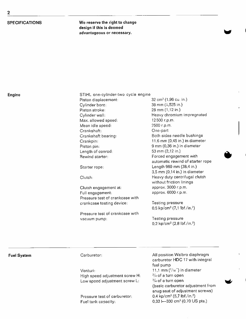
Engine STIHL one-cylinder-two cycle engine
Piston displacement: 32 cm3 (1,96 cu. in.)
Cylinder bore:
38 mm (1,525 in.)
Piston stroke:
28 mm (1,12 in.)
Cylinder wall: Heavy chromium impregnated
Max.allowed speed: 12500 r.P.m.
Mean idle speed: 2500 r.P.m.
Crankshaft: One-Part
Crankshaft bearing: Both sidesneedle bushings
Crankpin:
11,6 mm (0,a5 in.)in diameter
Piston pin: 9 mm (0,36 in.)in diameter
Length of conrod:
53 mm (2,12 in.)
Rewind starter:
Forced engagement with
automatic rewindof starter roPe
Starter rope: Length 960 mm (38'ain.)
3,5mm (0,1a in.)in diameter
Clutch:
Heavy duty centrifugal clutch
without friction linings
Clutch engagement at: approx' 3000 r.p.m.
Fullengagement:
approx. 6000 r.p.m'
Pressure test of crankcase with
crankcase testing device: Testing pressure
0,5 kp/cm2 (7,1lbf ./in.2)
Pressure test of crankcase with
vacuum pump: Testing pressure
0,2 kp/ cm2 (2,8lbf./ in.2)
Fuelsystem Carburetor:
All position Walbrodiaphragm
carburetor HDC 17 with integral
fuel pump
Venturi: 11,1 mm (7/rc") in diameter
Highspeedadjustment screw H:
slt
of a turn open
Low speedadjustment screw L:
3lt
of a turn open
(basic carburetor adjustment from
snugseat of adjustment screws)
Pressure test of carburetor: 0,4 kp/cm2 (5,7lbf./in.2)
Fuel tank capacity: 0,33
l-330 cms(0,70 US pts')
U'l
tr
v
3
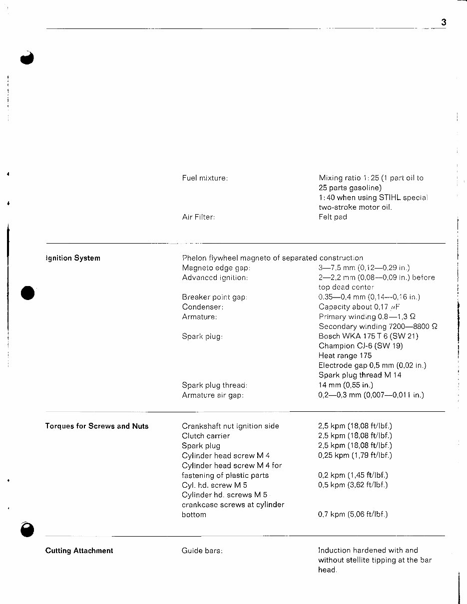
Fuelmixture:
Air Filter:
Mixingratio 1:25 (1 part oil to
25 partsgasoline)
1:40 when usingSTIHL special
two-stroke motoroil.
Feltpad
lgnition Systern Phelon flywheel magneto of separated construction
Magneto edge gap:
Advanced ignition:
Breaker pointgap:
Condenser:
Armature:
Spark plug:
3-7,5 mm (0,12-0,29in.)
2-2.2 mm (0,08-0.09in.)before
tnn do:ri aantar
0,35-0,4 mm (0,14-0,16in.)
Capacity about 0,17
,rF
Primary winding 0,8-1,3 f2
Secondary wlnding 7200-8800 Q
Bosch WKA 175 T 6 (SW 21)
Champion CJ-6 (SW 19)
Heatrange1 75
Electrode gap 0,5 mm (0,02 in.)
Sparkplug threadM 14
14 mm (0,55 in.)
0,2-0,3 mm (0,007-0,011 in.)
Spark plugthread:
Armature air gap:
Torques for Screwsand Nuts Crankshaft nut ignition side
Clutch carrier
Spark plug
Cylinder headscrew M 4
Cylinder headscrew M 4 for
fastening of plastic parts
Cyl. hd. screw M 5
Cylinder hd. screwsM 5
crankcase screwsat cvlinder
bottom
2,5kpm (18,08 ftllbf.)
2,5 kpm (18,08 fvlbf.)
2,5 kpm (18,08 ftllbf.)
0,25 kpm (1,79 ft/lbf .)
0,2 kpm (1,45 fVlbf.)
0,5 kpm (3,62 ftllbf.)
0,7 kpm (5,06 ftllbf.)
e
lnduction hardened with and
without stellite tipping at the bar
head.
Cutting Attachment Guidebars:
4
v !
Bar lengths:
Chain:
Chainspeed:
Chainlubrication:
Oil tank capacitY:
Chainsprocket:
25 cm (10 in.) guidebar without
stellite tipping at the bar head
30 cm
(12 in.) Duromatic
Auide
bar
with stellite tipping at the bar head
30 cm (12 in.) Rollomatic guidebar
with star shaped rollernose
r/a
"-oilomatic
chiPPer chain
STIHL chain model 3831
t/+ "-oilomatic-S-safetY
chain
STIHL chain model 3849
r/+ "-micromatic-semi-chisel chain
STIHL chain model3856
r/+ "-micromatic-S'safetY
chai n
STIHL chain model 3855
approx. 14,2
m/sek (46,58 ftlsec.)
at 8500 r.P.m.
Oil
pumpwith pumP
Plunger
governed by engine speed,
PUmPS
only when chain is rotating
0,18 l-180 cm3 (0,38 US
Pts.)
8 teeth lor
1/+"
chain
(
v
wiih 25 cm (10 in.)
bar and chain
015
015L,
4,2k9(9,2a
p)
Weight of Saw
01 5 L electron ic 4,4 kg (9,68
P.)
Extras
STIHL emergencY kit
Special muffler,
handguard
(
v
5
SAW CHAIN DRIVE AND CLUTCH
I
O
Function
'
I
{
"l
I
t
l
I
!
fhe power from the engine is trans- With increasing speed- at approx. Note:
a
mittedto the saw chainby a centri- 3000r.p.m. the clutch shoes held by The carburetorhas to be adjusted
fugalclutch. Thisclutch iscomposed the clutchspring are forced to the in such a way (see
"carburetor ad-
of clutch carrier,two clutch shoes outside.They are pressed against
justment")
that the chain does not
and one clutch spring.The washer the clutch drum thus transmitting rotate when engine is idling.
which is positioned behind the the enginepower to the saw chain.
clutch for the guidance of the clutch The chain sprocketalso drives the
shoes as well as the chainsprocket oil pump at engaged clutch, as the
with clutchdrum rivetedonto it are tooth profileengages in a provided
also partof the clutch assembly. recess at the small spur gear for
the
pump.
O
Troublins
The clutch is maintenancef ree.
Normal wear, however, cannot be
avoided. Therefore, the clutch and
chainsprocket must be checked on
propercondition periodically.
Troubles
Causes How to correct
Extraneous noises Engine is running too highwhen Adjustidle speedregulating screw
idlino
O
Saw chain does not stop running Springstretched or fatigued Replace spring
when idling Springhooksdamaged
Extreme chain wear Worn chain sorocket Replace chain sprocket
Disassembly
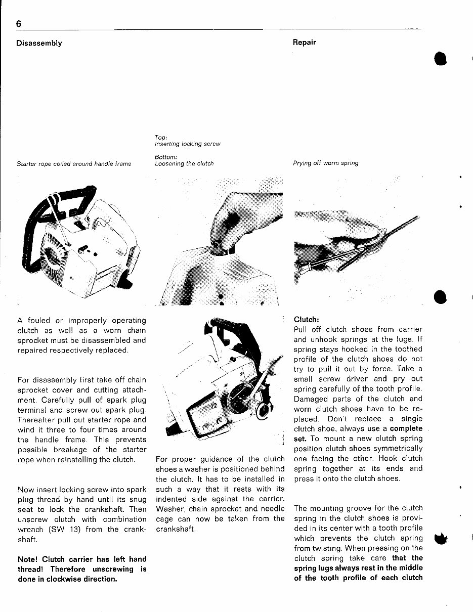
Starter rooe coiled around handle frame
A fouled or improperly operating
clutch as well as'a worn chain
sprocket must be disassembled and
repaired respectively replaced.
For disassembly first take off chain
sprocket cover and cutting attach-
ment. Carefully
pull of spark plug
terminal and screw out spark plug.
Thereafter pull out starter rope and
wind it three to four times around
the handle frame. This prevents
possible breakage of the starter
rope when reinstalling the clutch.
Now insertlocking screw into spark
plug thread by hand until its snug
seat to lock the crankshaft. Then
unscrew clutch with combination
wrench (SW 13) from the crank-
shaft.
Note! Clutch carrier has left hand
thread! Therefore unscrewing is
done in clockwise direction.
Top:
Inserting locking screw
Bottom:
Looseningthe clutch
Repair
Prying off worm spring
Clutch:
Pull off clutch shoes from carrier
and unhook springs at the lugs. lf
spring stays hooked in the toothed
profile of the clutch shoes do not
try to pull it out by force. Take a
small screw driver and pry out
springcarefully
of the tooth profile.
Damaged parts of the clutch and
worn clutch shoes have to be re-
placed. Don't replace a single
clutch shoe, alwaysuse a comPlete
set. To mount a new clutch sPring
position clutchshoes symmetrically
one facing the other. Hook clutch
spring together at its ends and
oress it onto the clutch shoes.
The mounting groove for the clutch
spring
in the clutchshoes is provi-
ded in its center
with a tooth profile
which prevents the clutch spring
from twisting.
When pressing on the
clutch spring take care that the
spring lugs alwaysrest in the middle
of the tooth profile of each clutch
'l>
-
-''
\
rf1
..
,. -i
i.. ;
r'l
For proper guidanceof the clutch
shoes a washer is
positioned
behind
the clutch.lt has to be installed in
such a way that it rests with its
indented side against the carrier.
Washer,chainsprocketand needle
cage can now be taken from the
crankshaft.
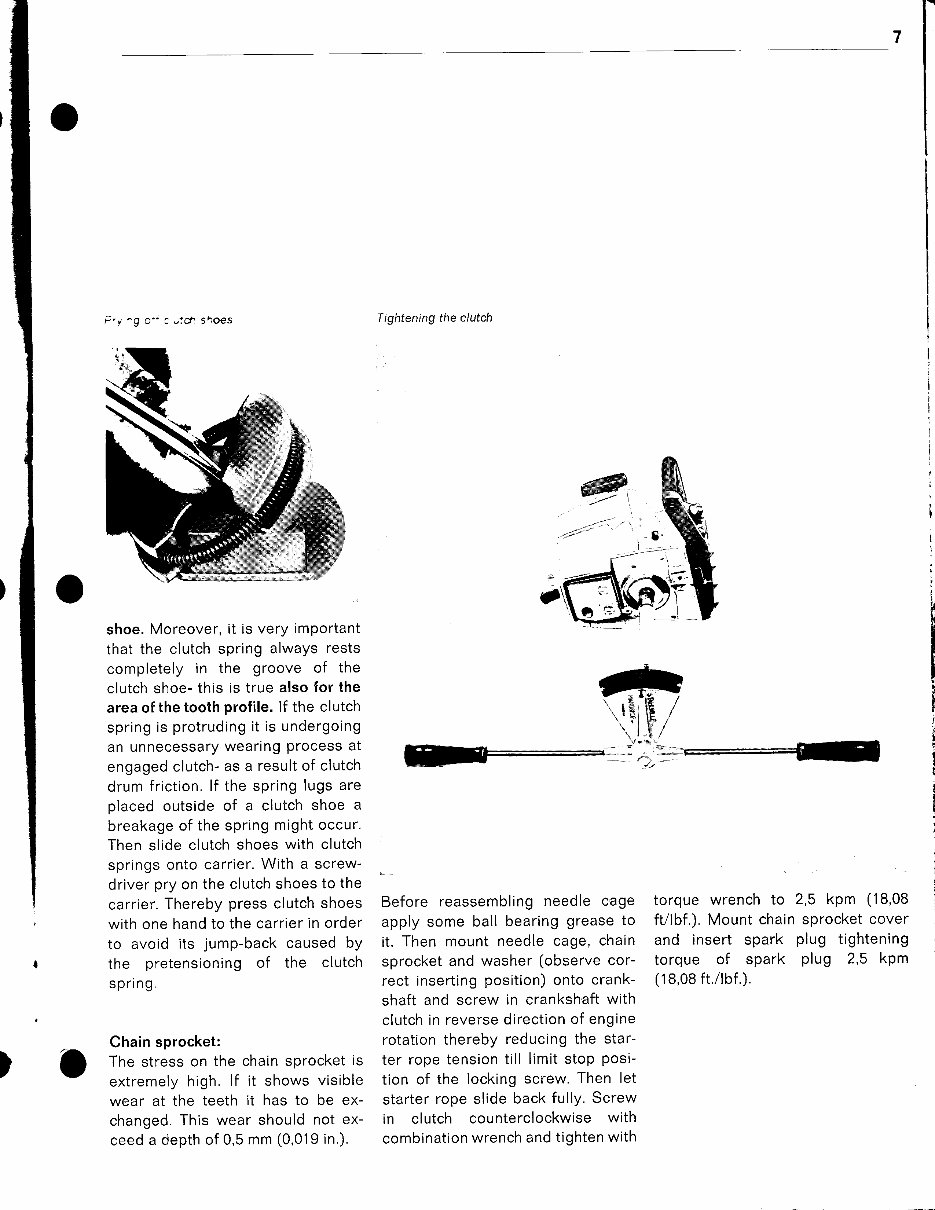
F.y 'g o" c ;ctt sboes
shoe.Moreover, it is very important
that the clutch spring always rests
completely in the groove of the
clutch shoe-this is true also for the
areaof the toothprofile. lf the clutch
springis protruding it is undergoing
an unnecessary wearing
Process
at
engaged clutch- as a result of clutch
drum friction. lf the spring lugs are
placed outside of a clutch shoe a
breakage of the springmightoccur.
Then slide clutchshoes with clutch
springsonto carrier. With a screw-
driver pry on the clutch shoesto the
carrier. Therebypress clutchshoes
with one handto the carrier in order
to avoid its jump-backcaused bY
the pretensioning of the clutch
spri ng.
Chainsprocket:
The stress on the chainsprocket is
extremelyhigh. lf it shows visible
wear at the teeth it has to be ex-
changed. This wear should not ex-
ceed a depthof 0,5 mm (0,019 in.).
Tightening the clutch
Before reassembling needle cage
apply some ball bearing greaseto
it. Then mount needle cage, chain
sprocketand washer (observe cor-
rect inserting position) onto crank-
shaft and screw in crankshaft with
clutch in reverse direction of engine
rotationthereby reducingthe star-
ter rope tensiontill limit stop
posi-
tion of the locking screw. Then let
starter rope slide back fully. Screw
in clutch counterclockwisewith
combination wrench and tighten with
torque wrench to 2,5 kpm (18,08
ftllbf.).Mount chain sprocket cover
and insert spark plug tightening
torque of spark plug 2,5 kpm
(18,08 ft./rbf.).
@
-tt"
''
t'.'t9,8
,
,,,
jf
/
FrTZ
)
t-
t-
ENGINE
Construction O(
The power chain saws are driven 2 heavy duty needle bushings. At The crankshaft at the ignitionside
I
by an aircooledone-cylinder two- the bearing seats
of the crankcase is providedwith a cam to activate
cycle engine.The crankcasecon- the crankshaft is sealedby separate the breaker point set.The conrod is
sists of two housing parts; as a oil sealson both sides. The bearing made of a special tempered case '
specialconstruction feature the cy- support between crankshaft and hardened steel.
linder at the same time serves as conrod is achieved by 12 cylindrical
crankcase half.Cylinder and piston rollers which are individually posi-
are made of a special aluminum tioned in a grease layer on the
alloy. Thecrankshaft
is drop forged. crankshaft and are kept in the
It is a onepart crankshaftand is guide groove on the crankshaft by
supported in the crankcase with the connecting rod.
O(
Troubling Causes
How to correct
Engine stopswhen idling, however, Sealing ring of crankshaft leaks Replace sealing rings
ooerates normal at full throttle
Crankcase defective (cracks) Replace crankcase
Motor doesnot reach full Air filterclogged Clean
performance or runs irregularly
Engine gets by-pass air by badly Mountcarburetor correctly if
fittedcarburetor necessary replace flangegasket
Piston ring leaky or broken Replace piston ring
Engine overheated lnsufficient cylinder cooling. Air Cleancooling air by passes.
intake openings at handle shroud
clogged or cooling fins fouled
Engine all right Trouble sourcemustbe looked for
in fuel system resPectivelY
carburetor or ignition system, see
respective paragraPh.
tl
9
o
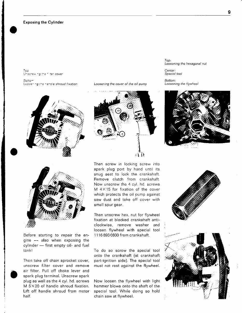
Exposing the Cylinder
Tap
U^scret ^g :-9' !e. Cover
Solo-
I coso'
5'' -
Before starting to repair the en-
gine - also when exposing the
cylinder - first empty oil- and fuel
tankl
Then take off chainsprocket cover,
unscrew f ilter cover and remove
air filter. Pull off choke lever and
spark plug terminal. Unscrew spark
plug as well as the 4 cyl. hd. screws
M 5X20 of handleshroud fixation.
Lift off handle shroud from motor
half .
Top:
Looseningthe hexagonal nut
Center:
Special tool
Bottom:
Loosenlngthe flywheel
o
Loosening the cover of the oil pump
Then screw in locking screw into
spark plug port by hand until its
snug seat to lock the crankshaft.
Remove clutch f rom crankshaft.
Now unscrew the 4 cyl. hd. screws
M 4X15 for fixation of the cover
which protects the oil pump against
saw dust and take off cover with
small spur gear.
Then unscrewhex. nut for flywheel
fixation at blocked crankshaft anti-
clockwise, remove washer and
loosen flywheel with special tool
111 6 893 0800 from crankshaft.
To do so screw the special tool
onto the crankshaft(at crankshaft
part-ignition side).The specialtool
must not rest againstthe flywheel.
Now loosen the flywheelwith light
hammer blows onto the shaft of the
special tool. While doing so hold
chain saw at flywhee,.
ffi3
i:l f&
You're Reading a Preview
What's Included?
Fast Download Speeds
Online & Offline Access
Access PDF Contents & Bookmarks
Full Search Facility
Print one or all pages of your manual
$31.99
Viewed 11 Times Today


Secure transaction
What's Included?
Fast Download Speeds
Online & Offline Access
Access PDF Contents & Bookmarks
Full Search Facility
Print one or all pages of your manual
$31.99
This Service Manual for the STIHL 015 015L CHAINSAW is a comprehensive resource for immediate repairs. It contains detailed technical data, diagrams, and a complete list of parts. Whether you are a professional mechanic or a DIY enthusiast, this manual is a valuable tool.
- Introduction
- Specifications
- Clutch, Chain Drive, Chain Brake And Chain Tensioner
- Engine
- Ignition System
- Rewind Starter
- AV Handle System
- Master Control / Handle System
- Chain Lubrication
- Fuel System
- Special Servicing Tools And Aids
This Service Repair Manual is available in PDF format and is compatible with all versions of Windows and Mac. It is written in English and requires Adobe Reader for access. The manual provides step-by-step instructions, making it suitable for all skill levels, and can be easily accessed in the garage or workshop.


