

HUSQVARNA CHAINSAW 340 345 346XP Full Service & Repair Manual
What's Included?
Fast Download Speeds
Online & Offline Access
Access PDF Contents & Bookmarks
Full Search Facility
Print one or all pages of your manual

Workshop manual
101 90 26-26
340, 345, 350
346XP, 351

English – 1
Workshop manual
Husqvarna 340, 345, 346XP/G, 350, 351 /G
Contents
Introduction ........................................................... 2
Safety regulations ................................................. 3
General instructions ........................................... 3
Special instructions ............................................ 3
Special tools .......................................................... 4
Technical data ....................................................... 6
Construction and function ................................... 8
Carburettor ......................................................... 8
Troubleshooting .................................................. 10
Repair instructions ............................................. 12
Chain brake ...................................................... 12
Silencer ............................................................ 14
Chain catcher ................................................... 14
Stop switch ....................................................... 15
Stop switch – resistance measurement ........... 15
Choke control ................................................... 16
Throttle trigger .................................................. 17
Hand grip heater .............................................. 18
Starter assembly .............................................. 20
Starter cord ...................................................... 21
Recoil spring .................................................... 21
Ignition module – testing .................................. 22
Ignition module and flywheel ............................ 23
Generator ......................................................... 24
Centrifugal clutch ............................................. 26
Oil pump ........................................................... 28
Carburettor ....................................................... 31
Carburettor – pressure testing ......................... 34
Carburettor – adjustment ................................. 36
Fuel tank .......................................................... 38
Fuel hose ......................................................... 39
Piston and cylinder ........................................... 40
Decompression valve – pressure testing ......... 41
Cylinder – pressure testing .............................. 43
Crankcase and crankshaft ............................... 44
Crankshaft bearings ......................................... 46
Repairing damaged threads ............................. 48
Guide bar bolts ................................................. 48
Fuel filter .......................................................... 48
Appendix A, Carburettor – EPA models ........... 49

2 – English
Arrangement of the manual
This workshop manual can be used in two different
ways.
• To repair a specific sub-assembly on a chainsaw.
• To dismantle and reassemble a complete
chainsaw.
Repairing a specific sub-assembly
If a specific sub-assembly on the chainsaw needs
to be repaired:
1. Look up the page referring to the relevant sub-
assembly.
2. Follow the instructions under the headings:
Removal/Dismantling
Cleaning and inspection
Refitting/Reassembly
Dismantling and reassembling the entire
chainsaw
If the entire chainsaw is to be dismantled, follow
the instructions under the heading “Removal/
Dismantling”.
Work through the manual and follow the instruc-
tions given in each section under the heading
“Removal/Dismantling”.
Then follow all the “Cleaning and inspection”
instructions in each section.
Working from the back of the manual, follow all the
instructions under the headings “Refitting/
Reassembly” in reverse order.
Each of the sections covering removal/dismantling
and refitting/reassembly include the relevant
lubrication instructions and bolt torques for each
stage of repair.
Construction and function
This chapter gives a simple description of the
chainsaw carburettor and its various parts.
Introduction
Troubleshooting
These pages describe the most common faults that
affect a chainsaw. They are divided into four
different groups with the most likely faults de-
scribed first.
Repair instructions
The section that describes how to repair the
chainsaw consists of detailed, step-by-step instruc-
tions. It explains in detail the special tools, lubri-
cants and bolt torques that are needed when
working on each component.
This workshop manual covers the following
chainsaw models:
340
345
350
351
351 G
346 XP
346 XPG

English – 3
General instructions
This workshop manual gives detailed instructions
on how to troubleshoot, repair and test a chainsaw.
This section also describes the various safety
precautions that should be taken when carrying out
repairs.
The workshop manual has been written for person-
nel who are assumed to have general experience
of repairing and servicing chainsaws.
Workshops where chainsaws are repaired must be
equipped with safety equipment that meets local
regulations.
No-one should carry out repairs on a chainsaw
until they have read and understood the contents
of this workshop manual.
Chainsaws are type-approved to meet the relevant
safety legislation, but this only applies when the
saw is fitted with the cutting equipment specified in
the user’s manual. The fitting of any other equip-
ment, or of accessories or parts that are not
approved by Husqvarna, could mean that the saw
no longer meets these safety requirements and the
person who carried out the work may be held
responsible for its non-conformance.
In this workshop manual the following boxes
indicate where caution should be taken.
Special instructions
The fuel that is used in a chainsaw poses the
following hazards:
• The fuel and its fumes are toxic.
• May cause irritation to skin or eyes.
• May cause breathing difficulties.
• Highly flammable.
When using compressed air the air jet should
never be pointed at the body. Air can be forced into
the bloodstream and cause fatal injury.
Wear ear protection when testing saws.
After testing a saw do not touch the silencer until it
has cooled down. The silencer gets very hot and
you may burn yourself. Wear protective gloves
when working on the silencer.
The guide bar, chain and clutch cover (chain brake)
must be fitted before the saw is started. If not, the
clutch may come loose and cause injury.
Poor chain lubrication can result in failure of the
chain, which could cause serious or fatal injury.
Take care to ensure that the spring inside the
starter assembly does not fly out and cause injury.
Wear eye protection. If the spring is under com-
pression when the pulley is removed it could fly out
and cause injury.
Before removing the tensioning spring from the
chain brake, ensure that the brake is in the on
position, otherwise the spring may fly out and
cause injury.
After repair, the chain brake must be checked as
described on page 13.
Always consider the fire risk. A chainsaw can
produce sparks that could start a fire.
Inspect the chain catcher and replace it if it is
damaged.
WARNING!
The warning text warns of the risk
of personal injury if the instruc-
tions are not followed.
NOTE!
The warning text warns of the risk of
material damage if the instructions are
not followed.
Safety regulations
!

4 – English
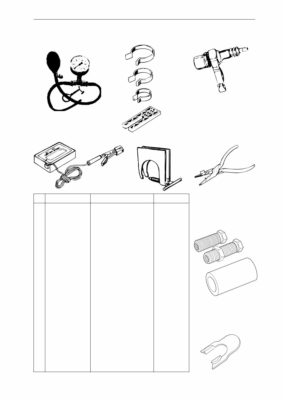
Special tools
4
5
8
11
12
10
1
2
3
7
6
9
English – 5
Item Description Used for Order no.
1 Clutch tool Centrifugal clutch 502 54 16-01
2 Piston stop Locking crankshaft 502 54 15-01
3 Stop plate Locating intake gaiter 502 54 17-01
4 Fuel filter hook Withdrawing the fuel filter 502 50 83-01
5 Allen key For M5 bolts 502 50 18-01
6 Puller Frame bearing 504 90 90-02
7 Sleeve, sealing ring Removing flywheel 502 54 20-01
8 Mandrel, sealing ring Removing crankshaft 502 54 21-01
9 Cover plate Sealing during pressure testing 502 54 11-02
10 Pressure tester Connection to cylinder 503 84 40-02
11 Feeler gauge Adjusting ignition module 502 51 34-02
12 Clamp stand Clamping the saw 502 51 02-01
13 Pressure gauge Pressurisation during testing 502 50 38-01
14 Piston fitting kit Fitting piston 502 50 70-01
15 Test plug Checking ignition module 502 71 13-01
16 Rev counter Adjusting carburettor 502 71 14-01
17 Removal tool Removing crankshaft 502 51 61-01
18 Assembly pliers Fitting spark plug guard 502 50 06-01
19 a Assembly tool right-hand thread 502 70 45-06
19 b Assembly tool left-hand thread 502 70 45-07
19 c Assembly tool Sleeve 502 70 84-01
20 Stop plate Removing crankshaft 502 54 18-01
14 15
16
19 a
20
18 17
13
19 b
19 c
Special tools
6 – English
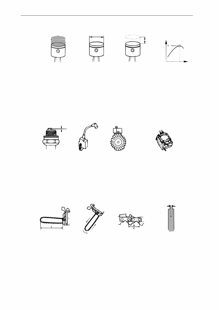
Displacement Cylinder bore Stroke Max power/speed
cm
3
/cubic inches Ø mm/Ø inches mm/inches kW/hp/rpm
340: 40.8 / 2.48 40.0 / 1.60" 32.5 / 1.28" 2.0/ 2.7 /9,000
345: 45.0 / 2.73 42.0 / 1.65" 32.5 / 1.28" 2.2/ 3.0 /9,000
346XP/G: 45.0 / 2.73 42.0 / 1.65" 32.5 / 1.28" 2.5/ 3.4 /9,600
350: 49.4 / 3.0 44.0 / 1.73" 32.5 / 1.28" 2.3/ 3.1 /9,000
351 /G: 49.4 / 3.0 44.0 / 1.73" 32.5 / 1.28" 2.3/ 3.1 /9,000
Spark plug gap Ignition system Air gap Carburettor type
mm/inches mm/inches
340: 0.5 / 0.02" FHP CD 0.3 / 0.012" Walbro HDA 154A (159A US only)
345: 0.5 / 0.02" FHP CD 0.3 / 0.012" Walbro HDA 154A (159A US only)
346XP/G: 0.5 / 0.02" FHP CD 0.3 / 0.012" Walbro HDA 154A (159A US only)
350: 0.5 / 0.02" FHP CD 0.3 / 0.012" Walbro HDA 154A (159A US only)
351 /G: 0.5 / 0.02" FHP CD 0.3 / 0.012" Walbro HDA 154A (159A US only)
Effective cutting length Chain speed at Chain pitch Drive link
cm/inches max power – revs mm/inches mm/inches
m/s – rpm
340: 30-48 / 12"-19" 17.3 / 9,000 8.25 / 0.325" 1.3 / 0.050" - 1.5 / 0.058"
345: 30-48 / 12"-19" 17.3 / 9,000 8.25 / 0.325" 1.3 / 0.050" - 1.5 / 0.058"
346XP/G: 30-48 / 12"-19" 18.5 / 9,600 8.25 / 0.325" 1.3 / 0.050" - 1.5 / 0.058"
350: 30-48 / 12"-19" 17.3 / 9,000 8.25 / 0.325" 1.3 / 0.050" - 1.5 / 0.058"
351 /G: 30-48 / 12"-19" 17.3 / 9,000 8.25 / 0.325" 1.3 / 0.050" - 1.5 / 0.058"
Technical data
English – 7
Technical data
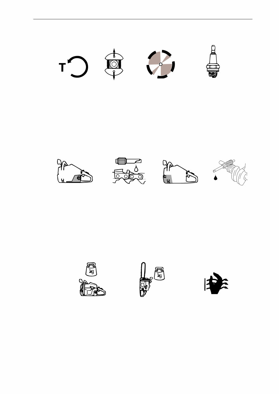
Idling speed Engagement speed Max. speed Spark plug
rpm rpm rpm
340: 2,700 3,800 12,500 Bosch RCJ 7Y, NGK BPMR 7A
345: 2,700 3,800 12,500 Bosch RCJ 7Y, NGK BPMR 7A
346XP/G: 2,700 3,800 14,700 Bosch RCJ 7Y, NGK BPMR 7A
350: 2,700 3,800 13,000 Bosch RCJ 7Y, NGK BPMR 7A
351 /G: 2,700 3,800 13,000 Bosch RCJ 7Y, NGK BPMR 7A
rpm
Fuel tank capacity Oil pump capacity at Oil tank capacity Automatic oil pump
Litres/US pints 8,500 rpm, Litres/US pints
ml/min
340: 0.5 / 1.06 9 0.25 / 0.53 Yes
345: 0.5 / 1.06 9 0.25 / 0.53 Yes
346XP/G: 0.5 / 1.06 5 - 10 0.28 / 0.59 Yes
350: 0.5 / 1.06 5 - 10 0.25 / 0.53 Yes
351 /G: 0.5 / 1.06 5 - 10 0.28 / 0.59 Yes
GAS
OIL
Weight without bar and chain Weight with bar and chain Heated hand grips
kg / lbs kg / lbs
340: 4.7 / 10.4 5.5 / 12.1 -
345: 4.7 / 10.4 5.5 / 12.1 -
346XP: 4.8 / 10.6 5.6 / 12.2 -
346XPG: 4.8 / 10.6 5.6 / 12.2 Yes
350: 4.8 / 10.6 5.6 / 12.2 -
351: 4.8 / 10.6 5.6 / 12.2 -
351G: 4.8 / 10.6 5.6 / 12.2 Yes
8 – English
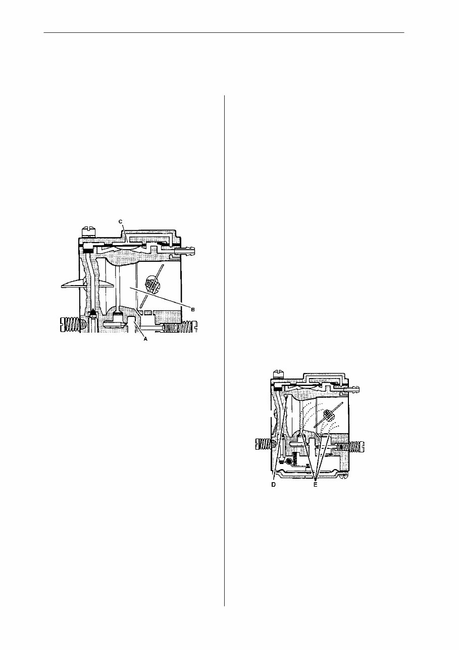
The carburettor works in different ways depending
on the setting:
• Cold start mode
• Idling mode
• Part throttle mode
• Full throttle mode
In the cold start mode the choke valve (D) is
completely closed. This increases the vacuum in
the carburettor so that fuel is sucked through the
diffuser jets faster (E).
Construction and function
Carburettor
• The pump unit (C) pumps fuel from the tank to
the metering system inside the carburettor. One
side of the pump diaphragm is connected to the
crankcase and pulses as a result of pressure
changes in the crankcase. The other side of the
diaphragm sucks in the fuel.
• The metering unit (A) which contains the jets
and the fuel control mechanism. This measures
out the right amount of fuel to suit the speed of
the saw and the power demand.
• The mixing unit (B) consists of the choke,
diffuser jets and throttle valve. This is where the
air and fuel are mixed to create a flammable
mixture.
The carburettor consists of three sub-systems:
English – 9
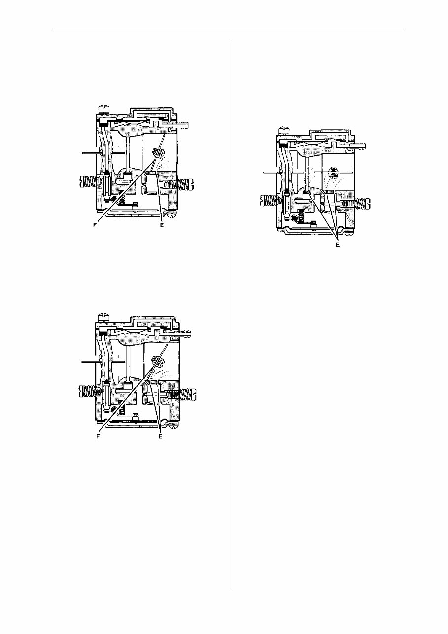
Construction and function
In part throttle mode the throttle valve (F) is par-
tially open. Fuel is supplied through the diffuser jets
(E).
In full throttle mode both valves are open and fuel
is supplied through all the diffuser jets (E).
In idling mode the throttle valve (F) is closed. Air is
sucked through an aperture in the throttle valve
and a small amount of fuel is supplied through the
diffuser jet (E).
You're Reading a Preview
What's Included?
Fast Download Speeds
Online & Offline Access
Access PDF Contents & Bookmarks
Full Search Facility
Print one or all pages of your manual
$39.99
Viewed 72 Times Today


Secure transaction
What's Included?
Fast Download Speeds
Online & Offline Access
Access PDF Contents & Bookmarks
Full Search Facility
Print one or all pages of your manual
$39.99
Get instant access to the Complete Factory Service Repair Workshop Manual without any extra fees or expiry dates. This Professional Manual is suitable for both professional Mechanics and Technicians, as well as DIY enthusiasts. It covers all repairs, servicing, and troubleshooting procedures with detailed photos, diagrams, step-by-step instructions, and highly detailed exploded diagrams & pictures to ensure every job is completed correctly.
Print out a single page or the entire manual as per your choice. This Manual can be used on multiple computers without any limitations or trial periods, and it does not expire or require any renewal fees. It is fully compatible with all Windows & MAC Computers.


