Contents 1. PRECAUTIONS (SAFETY WARNINGS).......................................................................... 5 2. PRODUCT SPECIFICATIONS......................................................................................... 8 2-1. Introduction of Main Function................................................................................................ 8 2-2. Model Specification .............................................................................................................. 9 2-3. Basic Specification ............................................................................................................. 10 2-3-1. Electric Parts Specification .............................................................................................. 11 2-3-2. Electric Component ......................................................................................................... 12 2-4. Dimensions (mm/inch) ........................................................................................................ 13 2-5. Optional Material Specification ............................................................................................ 14 3. DISASSEMBLY & REASSEMBLY ................................................................................. 15 3-1. PRECAUTION..................................................................................................................... 15 3-2. Assembly Hinge-Up Disassembling (Freezing Compartment) .............................................. 16 3-3. Assembly Hinge-Up Disassembling (Show Case of Fridge Compartment) ........................... 17 3-4. Assembly Hinge-Up Disassembling (Fridge Compartment).................................................. 18 3-5. Assembly Locker Disassembling (Fridge Compartment) ...................................................... 19 3-6. Cover Multi/Evaporator (Fan Motor/Motor-Driven Damper) Disassembling .......................... 27 3-7. Water Filter (Assembly & Disassembly) ................................................................................ 30 3-8. Case Water Filter ................................................................................................................ 31 3-9. Cover-Display & Water-Dispenser ....................................................................................... 32 3-10. Water-Dispenser ............................................................................................................... 33 3-11. Deodorizer ........................................................................................................................ 34 3-12. Evaporator ........................................................................................................................ 35 3-13. Main PCB and Inverter PCB Disassembling (whole) .......................................................... 36 3-14. COMP Cooling Fan Replacing .......................................................................................... 37 3-15. COMP Cooling Fan Motor Replacing ................................................................................ 38 3-16. Relay Protector O/L disassembling (Whole) ....................................................................... 39 3-17. Step Valve Disassembling (whole) ..................................................................................... 40 3-18. Ice Maker Compartment ................................................................................................... 41 3-19. Auger-Motor ..................................................................................................................... 42 3-20. Disassembling the internal handle ..................................................................................... 43 3-21. Disassembling the external handle .................................................................................... 43 4. TROUBLESHOOTING ................................................................................................... 44 4-1. Function for failure diagnosis............................................................................................... 44 4-2. Diagnostic method according to the trouble symptom(Flow Chart)...................................... 58
Contents 5. PCB DIAGRAM .............................................................................................................. 69 5-1. PBA Layout with part position ............................................................................................. 69 5-2. PBA Layout with part position (Inverter Board) .................................................................... 70 5-3. Connector Layout with part position (Main Board) ............................................................... 71 5-4. Connector Layout with part position (Inverter Board) ........................................................... 72 6. Wiring Diagram ............................................................................................................. 73 7. Block Diagram .............................................................................................................. 74 7-1. Whole block diagram .......................................................................................................... 74 7-2. Inverter Block Diagram........................................................................................................ 75 8. Model code table .......................................................................................................... 76
5 1. PRECAUTIONS (SAFETY WARNINGS) ● Unplug the appliance before the changing or repairing the electric parts. ● Use rated electronic Control equipment. ➝ Make sure to check out ModeL name, Rated voltage, Rated current, Operation Temp, etc. ● Upon repair, make sure that harnesses are not to be water-penetrated and are bundled tight. ➝ Should not be detached by a certain amount of external force. ● Upon repair, completely remove dust or other foreign substances from housing, harness, connector, etc. ➝ To prevent fire by tracking, short, etc. ● Check out whether water has penetrated into the electronic Control system. ➝ If there is any kind of trace, take necessary measures such as related component change, insulation tapping, etc. ● After repair, check out the assembled state of parts. ➝ It should be the same as the previous state. ● Check out the surrounding conditions. ➝ Change the location, if the fridge is located at humid, wet places or the installed state is unstable. ● In order to reduce the risk of electric shock the appliance must be properly grounded. ● Do not allow consumers to overload a certain outlet. ● Check out whether the power cord or the outlet is broken, squeezed, chopped off or heatdeformed. ➝ Repair or replace the defective power cord/outlet immediately. ➝ Make sure the power cord is not punctuated or stomped down. ● Do not allow consumers to keep food frayed or place bottles in the Freezer Room. ● Do not allow consumers to repair the fridge by themselves. ● Do not allow consumers to keep things except for food. ➝ Pharmaceutical, Chemical substances : These are not possible to be fine- Controlled with a consumer fridge. ➝ Flammable material (alcohol, benzene, ether, LPG, etc) : possibility of explosion.
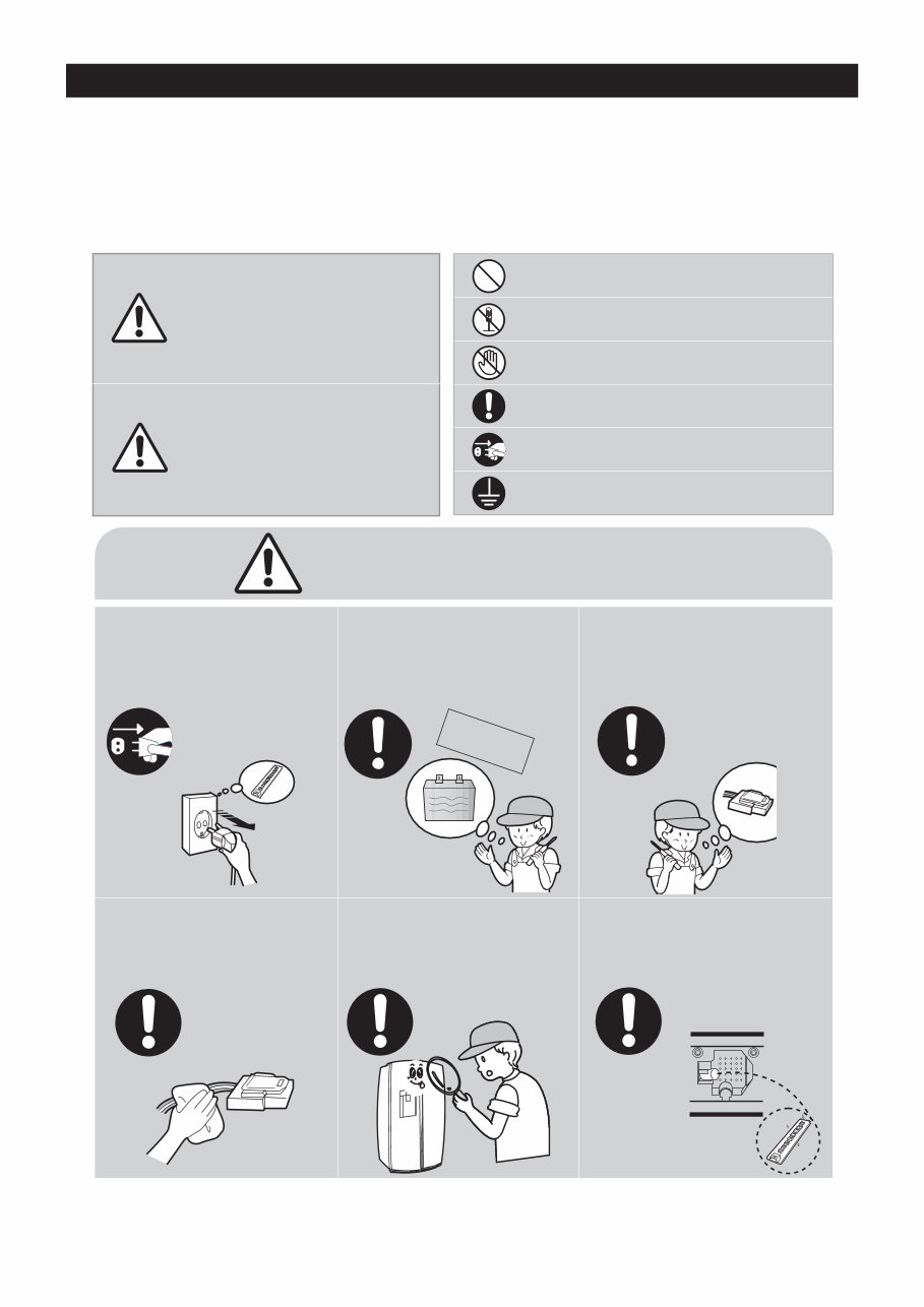
6 PRECAUTIONS(SAFETY WARNINGS) Read all instructions before repairing the product and follow the instructions in order to prevent danger or property damage. CAUTION/WARNING SYMBOLS DISPLAYED SYMBOLS Indicates that a danger of death or serious injury exists. Indicates that a risk of personal injury or material damage exists. means “Prohibited”. means “Do not disassemble”. means “No contact”. means ”Warning or Caution”. means “Earth or Ground”. means “Unplug the unit before preforming service” Plug out to exchange the interior lamp. • It may cause electric shock. Warning Warning & Caution Caution Unplug Use the rated components on the replacement. • Check the correct model, rated voltage, rated current, operating temperature and so on. On repair, make sure that the wires such as harness are bundled tightly. • Bundle tightly wires in order not to be detached by the external force and then not to be wetted. Check if there is any trace indicating the permeation of water. • If there is that kind of trace, change the related components or do the necessary treatment such as taping using the insulating tape. After repair, check the assembled state of components. • It must be in the same assembled state when compared with the state before disassembly. On repair, remove completely dust or other things of housing parts, harness parts, and check parts. • Cleaning may prevent the possible fire by tracking or short. Rated components Earth
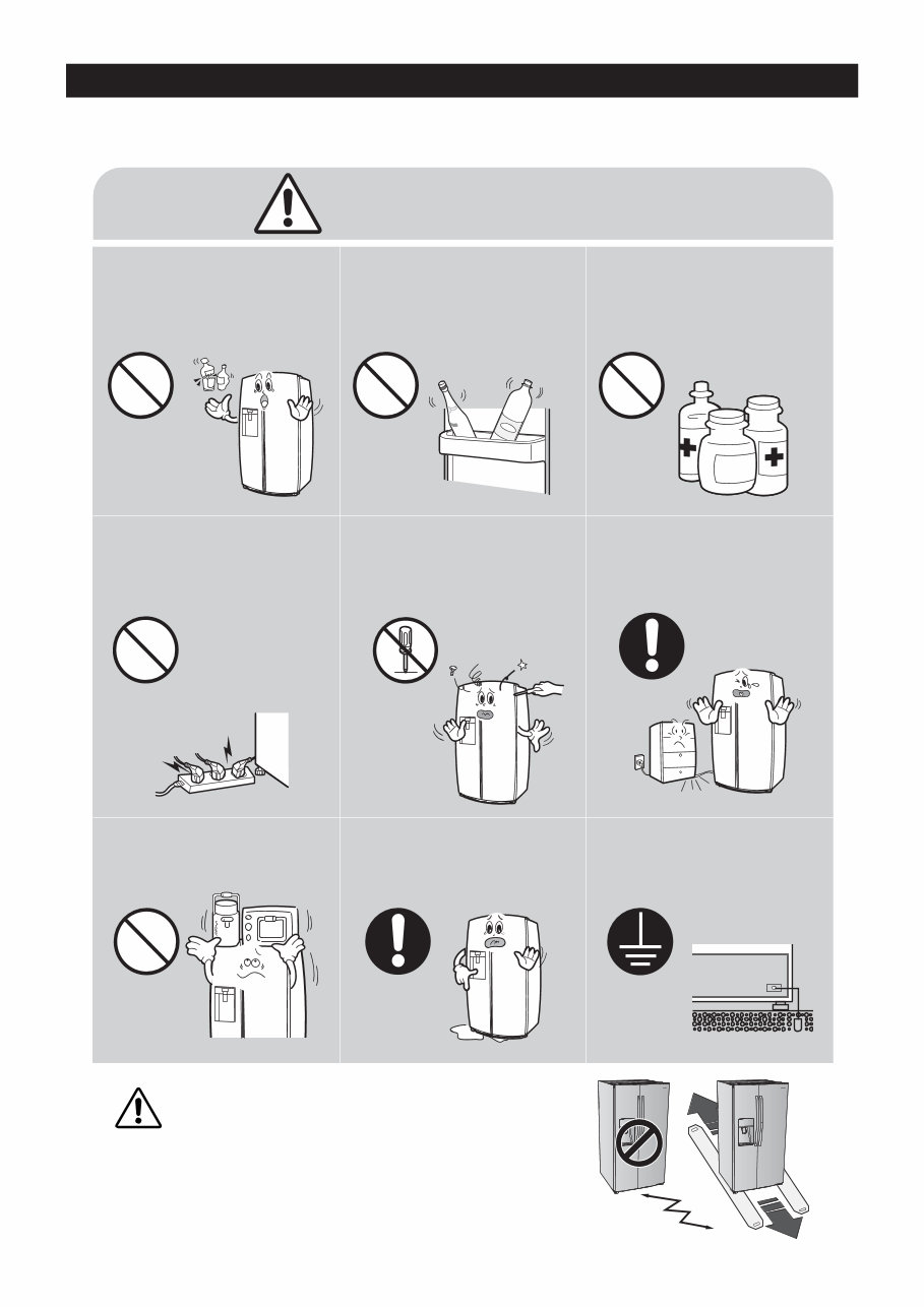
7 PRECAUTIONS(SAFETY WARNINGS) ❈ Please let users know following warnings & cautions in detail. Do not allow users to put bottles or kinds of glass in the freezer. • Freezing of the contents may inflict a wound. Do not allow users to store narrow and lengthy bottles or foods in a small multi-purpose room. • It may hurt you when refrigerator door is opened and closed resulting in falling stuff down. Prohibited Prohibited Prohibited Do not allow users to store pharmaceutical products, scientific materials, etc., in the refrigerator. • The products which need precise temperature control should not be stored in the refrigerator. Do not allow users to store articles on the product. • Opening or closing the door may cause things to fall down, with may inflict a wound. Prohibited Warning & Caution Do not allow users to disassemble, repair or alter. • It may cause fire or abnormal operation which leads to injury. Do not disassemble Do not allow users to plug several appliances into the same power receptable. • May cause abnormal generation of heat or fire. Prohibited Do not allow users to bend the power cord with excessive force or do not have the power cord pressed by heavy article. • May cause fire. Do not allow users to install the refrigerator in the wet place or the place where water splashes. • Deterioration of insulation of electric parts may cause electric shock or fire. In order to reduce the risk of electric shock the appliance must be properly grounded. Earth CAUTION When installing, servicing or cleaning behind the refrigerator, be sure to pull the unit straight out and push back in straight after finishing.
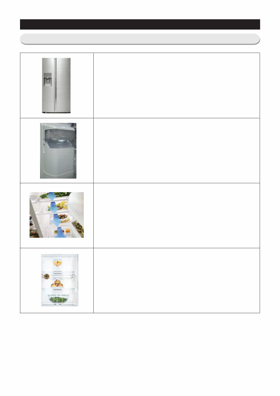
8 2. PRODUCT SPECIFICATIONS Larger Capacity • The Samsung Side by side Refrigerator has plenty of space for all your groceries, beverages, frozen foods and leftovers. It’s the perfect size for any occasion - holiday celebration, family reunion or Super Bowl party. Clearview In-door ice system • Located directly on the freezer door, the icemaker is easier to use and doesn’t take up valuable shelf space. The seethrough glass also lets you check on the amount of ice available at a glance Surround Multi Air Outlets • Cooling air flows out through multiple outlets in every shelf level. This provides even cooling throughout the refrigerator, and quickly returns back to temperature when the door has been opened. So it maintains an ideal temperature to keep your food fresh longer. LED Lighting • This space-saving LED fixture illuminates every corner of the fridge, so things are easier to find. Also LED emits less heat than conventional bulb lighting, affecting less damage to the temperature management. 2-1. Introduction of Main Function
9 PRODUCT SPECIFICATIONS 2-2. Model Specification NOTE - Key features of your new refrigerator Your Samsung Side-By-Side Refrigerator comes equipped with many space-saving, innovative storage and energy-efficient features. • Multi Airflow Provides even cooling throughout the refrigerator to maintain optimal temperatures to keep food fresh. • LED Lighting See everything in a new light with LED tower lighting. • Clear View Icemaker The Icemaker is located in the freezer door, this ensures that all the shelf space can be fully utilized. Ice cubes are quickly produced and the clear ice bucket lets you easily see the amount of ice cubes produced. • Premium Design Ice & Water Dispenser Quick and easy access to filtered water and cubed/crushed ice at your fingertips with the external dispenser. This operation instruction covers various models. The characteristics of your appliance may differ slightly from those described in this manual.
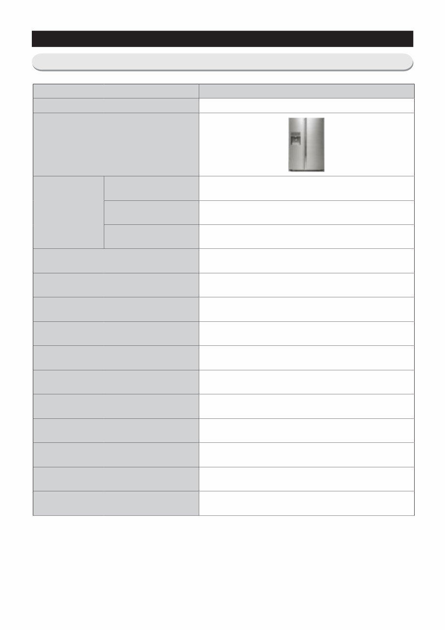
10 PRODUCT SPECIFICATIONS 2-3. Basic Specification ITEM Specification Model RH30H95** image Valid net capacity Gross capacity (LT) 29.5 cu.ft Freezing compartment (LT) 10.8 cu.ft Fridge Compartment (LT) 18.7 cu.ft Dimensions (width x depth x height) 912 x 916 x 1774 (35 7/8" x 36 1/8" x 69 6/8") Dimensions of package (width x depth x height) 972 x 995 x 1909 (38 2/8" x 39 1/8" x 75 1/8") Rated frequency (Hz) 60 Rated voltage (V) 115 Rated power consumption of motor (W) 155 Rated power consumption of heating device (W) 382 Refrigerator type Indirect Cooling Refrigerator Refrigerant R-134a Refrigerant charging volume 170 g Product weight (kg) 178 Weight of packaged product (kg) 190
This service and repair manual is an essential resource for anyone looking to troubleshoot and repair the Samsung RH30H9500SR/AA refrigerator. It contains in-depth information including product specifications, servicing precautions, disassembly and reassembly instructions, troubleshooting methods, block diagram, PCB diagram, and wiring diagram.
The manual is meticulously detailed and includes illustrated pictures and step-by-step instructions to guide both professional mechanics and DIY enthusiasts through the repair and servicing process.
It is important to note that this is the official service and repair manual, ensuring the highest quality and authenticity. The manual is available in a printable format, allowing easy access from any computer and printer. With instant access after payment, there are no shipping fees or waiting time, enabling prompt initiation of repairs.