

LG Refrigerator LMX21981ST Service Manual
What's Included?
Fast Download Speeds
Online & Offline Access
Access PDF Contents & Bookmarks
Full Search Facility
Print one or all pages of your manual
CAUTION
BEFORE SERVICING THE UNIT,
READ THE SAFETY PRECAUTIONS IN THIS MANUAL.
SERVICE MANUAL
COLOR: STAINLESS(ST)
SUPER WHITE(SW)
WESTERN BLACK(SB)
MODEL: LMX21981** /01
LMX25981** /01
www.Appliantology.org
Downloaded from www.Manualslib.com manuals search engine

E CN (E ngineering Change Number)
410G
304A
616J
317A
303B
303C
230B
230A
231B
231A
500A
616H
329D
243B
243A
300A
Loc No.
C apacitor,E lectric Appliance F ilm,B ox
Cover,PTC
C onnector,T ube
Drier Assembly
Thermistor Assembly,PTC
Overload Protect
Door Assembly,R efrigerator(Left)
Door Assembly,R efrigerator(R ight)
Door Foam Assembly,R efrigerator
Door Foam Assembly,R efrigerator
PCB Assembly
C onnector,T ube
Guide,Air
S topper,Door
S topper,Door
Comressor,Set
Part Name
L MX25981 /01
www.Appliantology.org
Downloaded from www.Manualslib.com manuals search engine

SAFETY PRECAUTIONS ....................................................................................................................................................... 2
1. SPECIFICATIONS............................................................................................................................................................... 3
2. PARTS IDENTIFICATION ................................................................................................................................................... 4
3. DISASSEMBLY.............................................................................................................................................................. 5-14
REMOVING AND REPLACING REFRIGERATOR DOORS ...............................................................................................5
DOOR INSTALLATION ....................................................................................................................................................... 6
DOOR .............................................................................................................................................................................. 7-8
TO REMOVE THE DISPENSER .........................................................................................................................................8
DOOR ALIGNMENT ............................................................................................................................................................8
FAN AND FAN MOTOR(Evaporator) .................................................................................................................................. 8
ICE FAN SCROLL ASSEMBLY REPLACEMENT ..............................................................................................................9
DEFROST CONTROL ASSEMBLY .................................................................................................................................... 9
LAMP .................................................................................................................................................................................. 9
CONTROL BOX-REFRIGERATOR .................................................................................................................................... 9
MULTI DUCT .................................................................................................................................................................... 10
MAIN PWB, DISPLAY PWB REPLACEMENT, FUNNEL REPLACEMENT......................................................................10
SUB PWB FOR DISPENSER, DUCT DOOR REPLACEMENT, ICE CORNER DOOR
REPLACEMENT, ICE MAKER ASSEMBLY.......................................................................................................................11
AUGER MOTOR COVER, AUGER MOTOR REPLACEMENT .........................................................................................12
DOOR ICE BIN ..................................................................................................................................................................13
HOW TO REMOVE AND REINSTALL THE PULLOUT DRAWER ...............................................................................14-17
4. ADJUSTMENT............................................................................................................................................................. 18-19
COMPRESSOR ................................................................................................................................................................ 18
PTC-STARTER ................................................................................................................................................................. 18
OLP(OVERLOAD PROTECTOR) ......................................................................................................................................19
TO REMOVE THE COVER PTC .......................................................................................................................................19
5. CIRCUIT DIAGRAM.......................................................................................................................................................... 20
6. TROUBLESHOOTING................................................................................................................................................. 21-25
COMPRESSOR AND ELECTRIC COMPONENTS.......................................................................................................... 21
OTHER ELECTRICAL COMPONENTS ........................................................................................................................... 22
SERVICE DIAGNOSIS CHART ........................................................................................................................................ 23
REFRIGERATION CYCLE .......................................................................................................................................... 24-25
7. OPERATION PRINCIPLE & REPAIR METHOD OF ICEMAKER .............................................................................. 26-28
8. DESCRIPTION OF FUNCTION, CIRCUITS & ERROR CODES..................................................................................29-45
9. EXPLODED VIEW & REPLACEMENT PARTS LIST ..................................................................................................... 46-
CONTENTS
- 2 -
Please read the following instructions before servicing your
refrigerator.
1. Unplug the power before handling any elctrical
componets.
2. Check the rated current, voltage, and capacity.
3. Take caution not to get water near any electrical
components.
4. Use exact replacement parts.
5. Remove any objects from the top prior to tilting the
product.
SAFETY PRECAUTIONS
www.Appliantology.org
Downloaded from www.Manualslib.com manuals search engine
21 cu. ft. / 025 cu. ft
1. SPECIFICATIONS
- 3 -
ITEMS SPECIFICATIONS
DOOR DESIGN Side Rounded
DIMENSIONS (inches) 35
3
/ 4 X 30
1
/ 4 X 69
3
/ 4 (WXDXH) 21cu.ft
35
3
/ 4 X 34
1
/ 4 X 69
3
/ 4 (WXDXH) 21cu.ft
NET WEIGHT (pounds)
302.58 (21cu.ft)
324.18 (25cu.ft)
COOLING SYSTEM Fan Cooling
TEMPERATURE CONTROL Micom Control
Full Automatic
DEFROSTING SYSTEM
Heater Defrost
DOOR FINISH Embossed Metal, VCM, Stainless
HANDLE TYPE Bar
INNER CASE ABS Resin
INSULATION Polyurethane Foam
ITEMS SPECIFICATIONS
VEGETABLE TRAY Opaque Drawer Type
COMPRESSOR Recipro
EVAPORATOR Fin Tube Type
CONDENSER Wire Condenser
REFRIGERANT R-134a (140 g)
LUBRICATING OIL ISO10 (280 ml)
DEFROSTING DEVICE SHEATH HEATER
LAMP
REFRIGERATOR LED Module(27)
FREEZER LED Module(9)
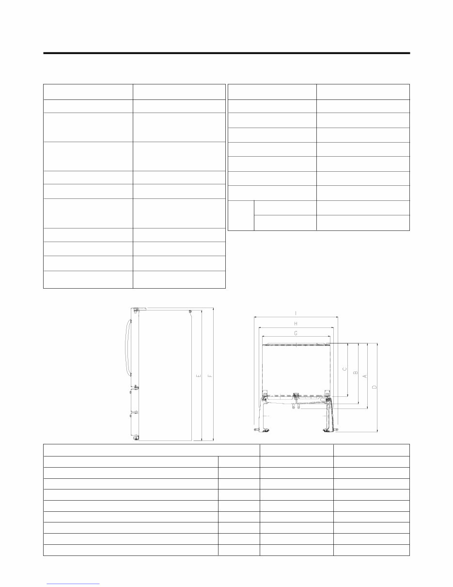
Description LMX21981** /01 LMX25981** /01
Depth w/ Handles A 30 in. 34 1/4 in.
Depth w/o Handles B 27 1/2 in. 31 1/4 in.
Depth w/o Door C 23 5/8 in. 27 7/8 in.
Depth (Total with Door Open) D 42 1/4 in. 46 1/2 in.
Height to Top of Case E 68 3/8 in. 68 3/8 in.
Height to Top of Door Hinge F 69 3/4 in. 69 3/4 in.
Width G 35 3/4 in. 35 3/4 in.
Width (door open 90 deg. w/o handle) H 39 1/4 in. 39 1/4 in.
Width (door open 90 deg. w/ handle) I 44 1/4 in. 44 1/4 in.
DIMENSIONS
www.Appliantology.org
Downloaded from www.Manualslib.com manuals search engine
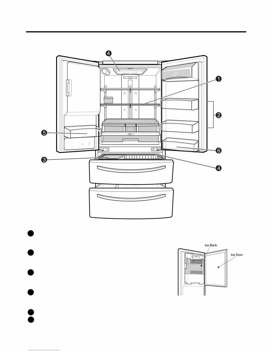
2. PARTS IDENTIFICATION
- 4 -
ADJUSTABLE REFRIGERATOR SHELVING
The refrigerator compartment shelves are adjustable to
allow flexibility for storage needs.
MODULAR DOOR BINS
Three interchangeable bins can be arranged to suit your
storage needs.
REMOVABLE ICE STORAGE BIN
The ice storage bin can be removed to fill ice
buckets,coolers,or pitchers.
INTERIOR LAMPS
Two separate LED arrays light the freezer and refrigerator
interiors.
FIXED DOOR BIN
FIXED DOOR BIN
1
2
3
4
5
6
www.Appliantology.org
Downloaded from www.Manualslib.com manuals search engine
- 5 -
3. DISASSEMBLY
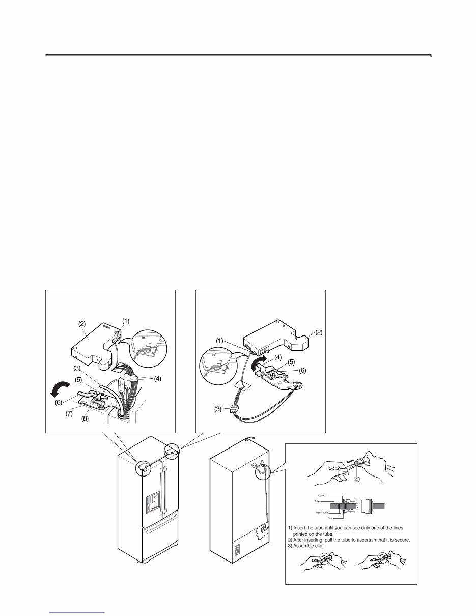
3-1 REMOVING AND REPLACING REFRIGERATOR DOORS
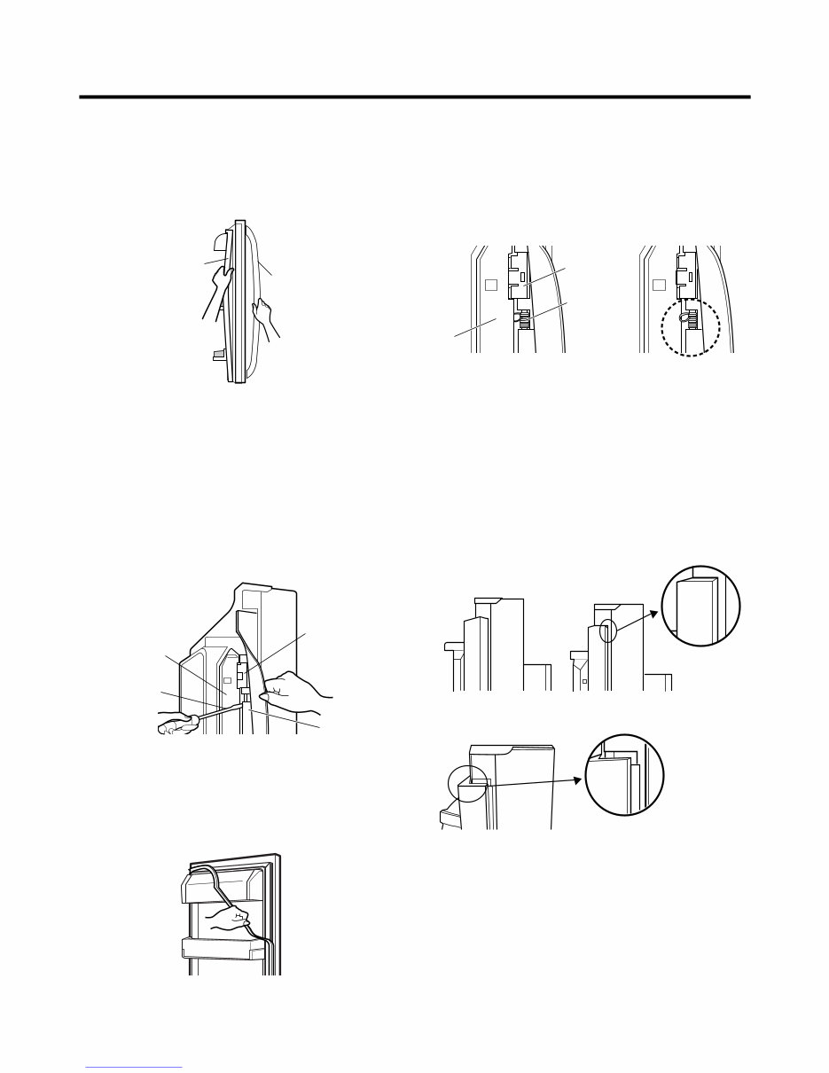
● Removing Refrigerator Door
w CAUTION: Before you begin, unplug the refrigerator. Remove food and bins from doors.
u Left Door -FIG. 2
1. Disconnect water supply tube by pushing back on the disconnect ring (4).-FIG. 1
2. Open door. Loosen top hinge cover screw (1).
Use flat tip screwdriver to pry back hooks on front underside of cover (3). Lift up cover.
3. Disconnect door switch wire harness (2). Remove cover.
4. Pull out the tube.
5. Disconnect the three wire harnesses (5). Remove the grounding screw (6).
6. Rotate hinge lever (7) counterclockwise. Lift top hinge (8) free of hinge lever latch (9).
w CAUTION: When lifting hinge free of latch, be careful that door does not fall forward.
7. Place door, inside facing up, down onto a non-scratching surface.
u Right Door -FIG. 3
1. Open door. Loosen top hinge cover screw (1). Lift up cover (3).
2. Disconnect door switch wire harness (2). Remove cover.
3. Disconnect wire harness (5).
4. Rotate hinge lever (6) clockwise. Lift top hinge (7) free of hinge lever latch (8).
w CAUTION: When lifting hinge free of latch, be careful that door does not fall forward.
5. Lift door up from middle hinge pin (9) door.
6. Place door, inside facing up, down onto a non-scratching surface.
Correct
Incorrect
Figure 2 Figure 3
Figure 1
www.Appliantology.org
Downloaded from www.Manualslib.com manuals search engine
- 6 -
3-2 DOOR
● Door Gasket Removal
1. Remove door frame cover
Starting at top of cover and working down, snap cover
out and away from door.
2. Remove gasket bracket clips
There are two clips on each door. Start bracket removal
near one of the middle clips.
1) Pull gasket back to expose gasket bracket clip and
door frame.
2) Insert a flat tip screwdriver into seam between gasket
bracket and door frame and pry back until clips snap
out.
3) Continue prying back along seam until all clips snap
out.
3. Remove gasket
Pull gasket free from gasket channel on the three
remaining sides of door.
● Door Gasket Replacement
1. Insert gasket bracket clips
1) Insert gasket bracket edge beneath door frame edge.
2) Turn upper gasket bracket spring so that the spring
ends are in the door channel.
3) Push in clip until you hear it snap securely into place.
4) Push in remaining clip until you hear it snap securely
into place.
Note: Make sure that no part of gasket bracket edge
protrudes from beneath door frame edge.
2. Insert gasket into channel
1) Snap gasket assembly into the door bracket.
<Inserting the Gasket Assembly into the Bracket Door>
Frame Cover
Handle
Door
Frame
Gasket
Bracket Clip
Flat Tip
Screwdriver
Gasket
Bracket
Figure 1
Figure 2
Figure 3
Door
Frame
Gasket
Bracket Clip
Spring
Incorrect Correct
Incorrect
Correct
Figure 4
Figure 5
www.Appliantology.org
Downloaded from www.Manualslib.com manuals search engine
- 7 -
2) Press gasket into channels on the three remaining
sides of door.
3. Replace door frame cover
Starting at top of cover and working down, snap cover
back into door.
.
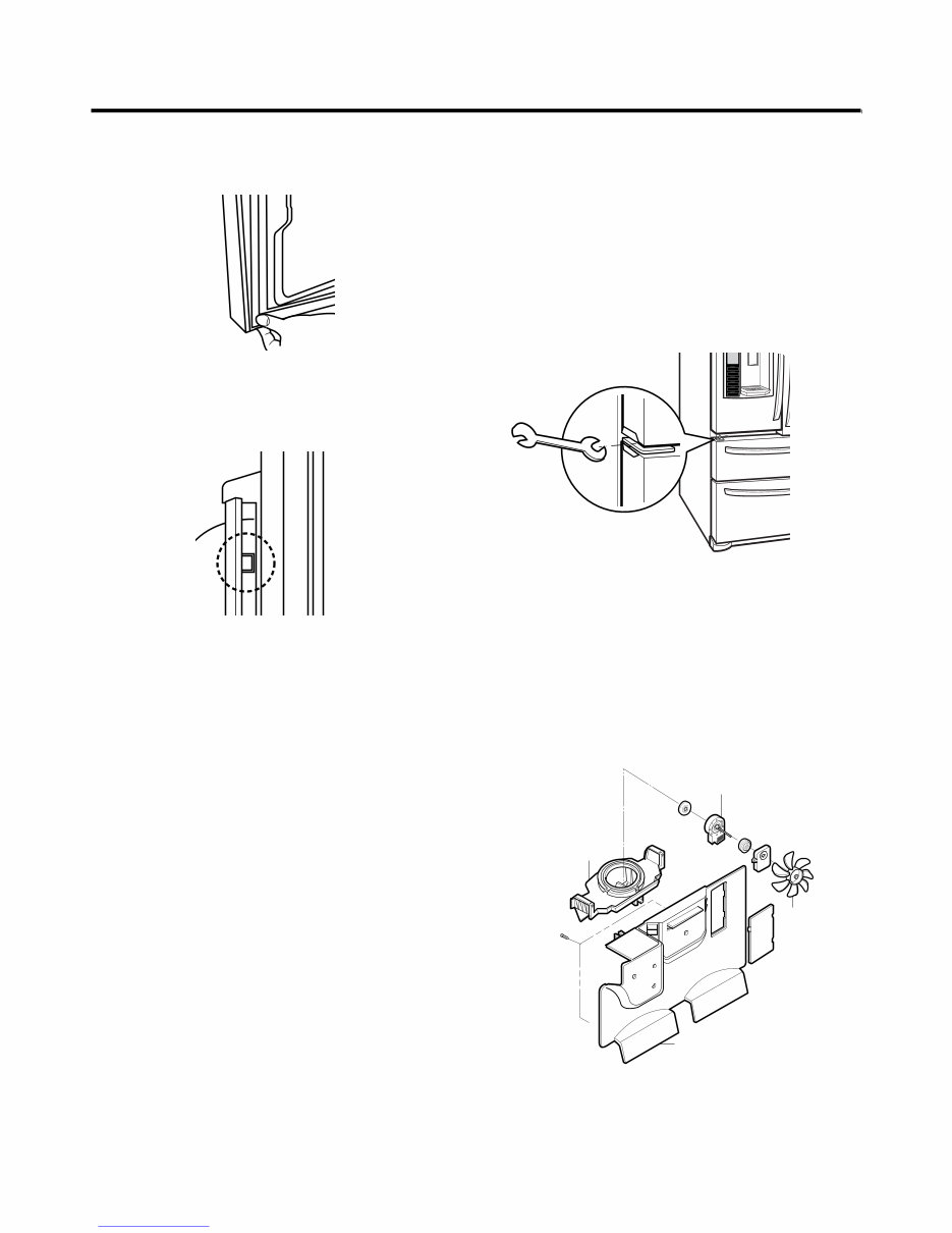
3-3 DOOR ALIGNMENT
If the space between your doors is uneven, follow the
instructions below to align the doors:
1. Remove the Base Grillie.
2. Turn the leveling legs (CCW) to raise or (CW) to lower
the height of the front of the refrigerator by using flat
blade screw driver or 11/32" wrench.
3. Use the wrench (Included with the User Manual) to
adjust the bolt in the door hinge to adjust the height.
(CCW to raise or CW to lower the height.)
3-4 FAN AND FAN MOTOR(EVAPORATOR)
1. Remove the freezer shelf. (If your refrigerator has an
icemaker, remove the icemaker first)
2. Remove the plastic guide for slides on left side by
unscrewing phillips head screws.
3. Remove the grille by removing one screw and pulling the
grille forward.
4. Remove the Fan Motor assembly by loosening 2 screws
and disassembling the shroud.
5. Pull out the fan and separate the Fan Motor and Bracket.
CAUTION
DO NOT ATTEMPT TO REMOVE THE MULLION :
REFRIGERANT LINES!
Figure 6
Figure 8
Figure 7
GRILLE
FAN MOTOR
FAN
BRACKET
MOTOR
Figure 9
www.Appliantology.org
Downloaded from www.Manualslib.com manuals search engine
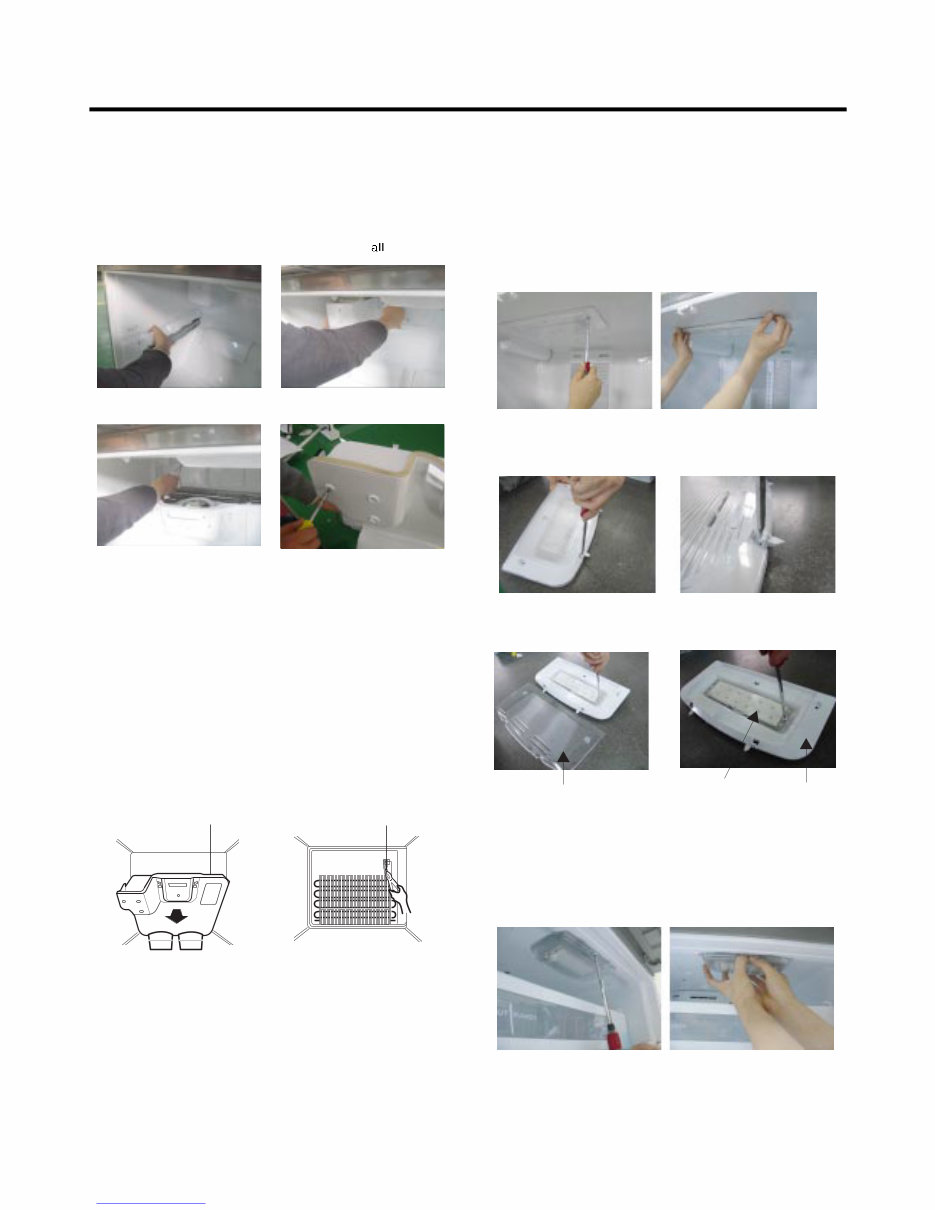
* Ice Fan Scroll Assembly Replacement
1) Remove the plastic guide for slides on left side by
unscrewing phillips head screws.
2) Pull the grille forward as shown in the second picture.
3) Disconnect wire harness of the grille
4) Remove the scroll assembly by loosening screws
3-5 DEFROST CONTROL ASSEMBLY
Defrost Control assembly consists of Defrost Sensor and
FUSE–M.
The Defrost Sensor works to defrost automatically. It is
attached to the metal side of the Evaporator and senses its
temperature. At 72°C, it turns the Defrost Heater off.
Fuse-M is a safety device for preventing over-heating of
the Heater when defrosting.
1. Pull out the grille assembly. (Figure 10)
2. Separate the connector with the Defrost Control
assembly and replace the Defrost Control assembly
after cutting the Tie Wrap. (Figure 11)
CAUTION
DO NOT ATTEMPT TO REMOVE THE MULLION :
REFRIGERANT LINES!
3-6 LAMP
Unplug Refrigerator, or disconnect power at the circuit
breaker.
If necessary, remove top shelf or shelves.
3-6-1 Refrigerator Compartment Lamp
1) Release 2 screws.
2) Hold both ends with your both hands and pull it
downward to remove it.
3) Use a flat tool as shown below to remove
the cover lamp.
4) As shown below, use a flat tool to remove
the cover lamp.
3-6-2 Freezer Compartment Lamp
1. Unplug refrigerator power cord form outlet.
2. Remove screw with driver.
3. Grasp the cover Lamp,pull the cover downward.
- 8 -
GRILLE ASSEMBLY
Figure 10
DEFROST-CONTROL
ASSEMBLY
Figure 11
Figure 12
Figure 13
Cover, Lamp
Case Lamp
LED, Assembly
Figure 14
Figure 15
(1) (2)
(3) (4)
www.Appliantology.org
Downloaded from www.Manualslib.com manuals search engine
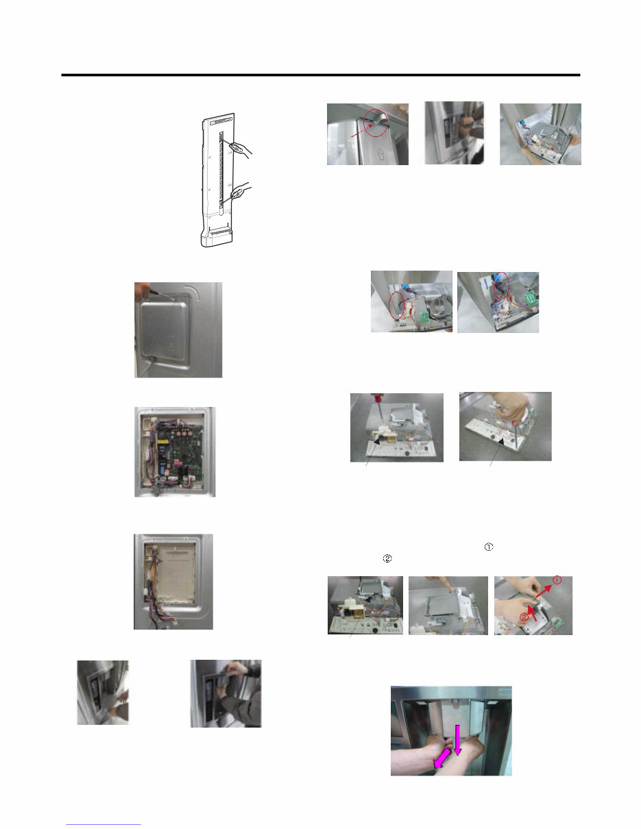
3-7 MULTI DUCT
1. Remove the upper and
lower Caps by using a flat
screwdriver, and remove
2 screws. (Figure 16)
2. Disconnect the lead wire
on the bottom position.
3-8 MAIN PWB
1) Loosen the 3 screws on the PWB cover.
2) Remove the PWB cover
3) Disconnect wire harness and replace the main PWB in
the reverse order of removal.
3-9 DISPENSER
w CAUTION: When replacing the dispensor cover in the
reverse order of removal, be careful that the lead wire
does not come out and the water tube is not pinched by
the dispensor,
3-10 DISPLAY PCB
As shown below, remove 1 case PCB fixing screw.
Remove the display PCB fixing screw.
3-11 ICE BUTTON ASSEMBLY
1) Remove the screw fixing the button lever.
2) Push the spring from the hanging hook to remove it.
3) Apply some pressure to the rib in direction and lift the
button in direction.
3-12 FUNNEL REPLACEMENT
Pull down and forward.
Figure 16
Case, PCB Display PCB
Button Lever
- 9 -
1) Pull out the darin 2) Hold the inner side
of cover dispenser
with both hands at the
handle side to pull it
out forward.
3) If nozzle is interfered with button , push and
pull out the bottom of button.
4) Rmove the
connected part of
Lead wire.
www.Appliantology.org
Downloaded from www.Manualslib.com manuals search engine
You're Reading a Preview
What's Included?
Fast Download Speeds
Online & Offline Access
Access PDF Contents & Bookmarks
Full Search Facility
Print one or all pages of your manual
$30.99
Viewed 76 Times Today


Secure transaction
What's Included?
Fast Download Speeds
Online & Offline Access
Access PDF Contents & Bookmarks
Full Search Facility
Print one or all pages of your manual
$30.99
Looking for more information on your LG Equipment? This comprehensive manual is perfect for professional mechanics and DIY enthusiasts alike. Whether you're using a Windows desktop, Mac, iPad, or a PDF reader, you can easily access and utilize this manual.
It's an ideal replacement for a missing copy and provides in-depth insights into your product, helping you avoid unscrupulous repair services. Upon completion of payment, the manual will be instantly available for download, eliminating the need to wait for unreliable postal delivery. Additionally, you can choose to print only the specific pages you require.
With a focus on technical details, this manual ensures satisfaction guaranteed for all your repair and maintenance needs.


