CAUTION BEFORE SERVICING THE UNIT, READ THE SAFETY PRECAUTIONS IN THIS MANUAL. MODEL : LFX31925** COLOR : STAINLESS(ST) SMOOTH BLACK(SB) SUPER WHITE(SW) REFRIGERATOR SERVICE MANUAL
- 2 - CONTENTS SAFETY PRECAUTIONS ....................................................................................................................................................... 2 1. SPECIFICATIONS ............................................................................................................................................................. 3 2. PARTS IDENTIFICATION ................................................................................................................................................. 4 3. DISASSEMBLY ................................................................................................................................................................ 5- REMOVING AND REPLACING REFRIGERATOR DOORS .......................................................................... 5 DOOR .............................................................................................................................................................. 6 DOOR ALIGNMENT ....................................................................................................................................... 7 FAN AND FAN MOTOR................................................................................................................................... 7 DEFROST CONTROL ASSEMBLY ................................................................................................................ 7 REFRIGERATOR LIGHT (TOP) .................................................................................................................. 8-9 MULTI DUCT .................................................................................................................................................. 9 DISPENSER ................................................................................................................................................. 10 DISPLAY PCB .............................................................................................................................................. 10 ICE BUTTON ASSEMBLY ............................................................................................................................ 10 WATER BUTTON ASSMEBLY ..................................................................................................................... 10 ICE CORNER DOOR REPLACEMENT ........................................................................................................ 10 ICEMAKER REPLACEMENT ....................................................................................................................... 11 SUB PCB FOR WORKING DISPENSER ..................................................................................................... 11 CAP DUCT MOTOR REPLACEMENT ......................................................................................................... 12 HOW TO REMOVE A ICE BIN ..................................................................................................................... 13 HOW TO INSERT A ICE BIN ........................................................................................................................ 13 HOW TO REMOVE AND REINSTALL THE PULLOUT DRAWER ......................................................... 14-15 WATER VALVE DISASSEMBLY METHOD .................................................................................................................... 16 FAN AND FAN MOTOR DISASSEMBLY METHOD......................................................................................................... 16 PULL OUT DRAWER ...................................................................................................................................................... 17 CAUTION : SEALED SYSTEM REPAIR ......................................................................................................................... 18 4. ADJUSTMENT ................................................................................................................................................................ 19 COMPRESSOR ................................................................................................................................................................ 19 5. CIRCUIT DIAGRAM ........................................................................................................................................................ 20 6. TROUBLESHOOTING .................................................................................................................................................... 21 7. PCB PICTURE ........................................................................................................................................................... 22-23 8. Troubleshooting With Error Display ....................................................................................................................... 24-35 9. Troubleshooting Without Error Display ................................................................................................................. 36-44 10. Reference .................................................................................................................................................................. 35-50 11. COMPONENT TESTING INFORMATION ................................................................................................................. 51-59 12. TROUBLESHOOTING .............................................................................................................................................. 60-72 13. ICEMAKER OPEARTING AND TROUBLE SHOOTING METHOD ......................................................................... 73-76 14. DESCRIPTION OF FUNCTION & CIRCUIT OF MICOM ........................................................................................... 77-80 SAFETY PRECAUTIONS Please read the following instructions before servicing your refrigerator. 1. Unplug the power before handling any elctrical componets. 2. Check the rated current, voltage, and capacity. 3. Take caution not to get water near any electrical components. 4. Use exact replacement parts. 5. Remove any objects from the top prior to tilting the product.
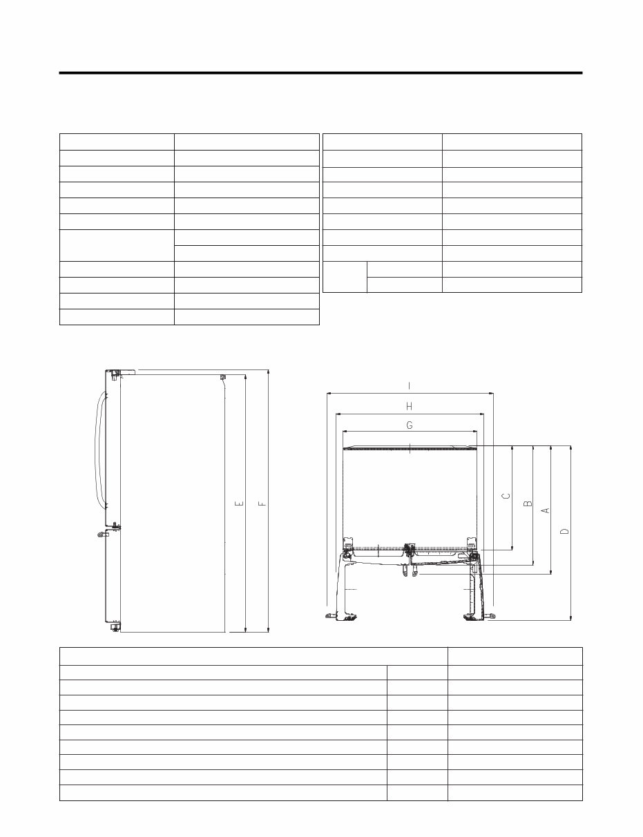
- 3 - 1. SPECIFICATIONS 1-1 LFX31925** DOOR DESIGN DIMENSIONS (inches) NET WEIGHT (pounds) COOLING SYSTEM TEMPERATURE CONTROL DEFROSTING SYSTEM DOOR FINISH HANDLE TYPE INNER CASE INSULATION ITEMS Side Rounded 35 3 /4 X 36 1 /4 X 70 1 /4 (WXDXH) 31cu.ft. 158kg (348lb) Fan Cooling Micom Control Full Automatic Heater Defrost PCM, VCM, Stainless Bar ABS Resin Polyurethane Foam SPECIFICATIONS ● 31 cu.ft. VEGETABLE TRAY COMPRESSOR EVAPORATOR CONDENSER REFRIGERANT LUBRICATING OIL DEFROSTING DEVICE ITEMS Clear Drawer Type Linear Fin Tube Type Spiral Condenser R-134a (135 g) ISO10 (280 ml) SHEATH HEATER LED Module LED Module SPECIFICATIONS LAMP REFRIGERATOR FREEZER ● DIMENSIONS Depth w/ Handles Depth w/o Handles Depth w/o Door Depth (Total with Door Open) Height to Top of Case Height to Top of Door Hinge Width Width (door open 90 deg. w/o handle) Width (door open 90 deg. w/ handle) A B C D E F G H I 36 1/4 in 33 3/4 in 29 1/2 in 48 1/8 in 68 3/4 in 70 1/4 in 35 3/4 in 40 in 45 in Description LFX31925**
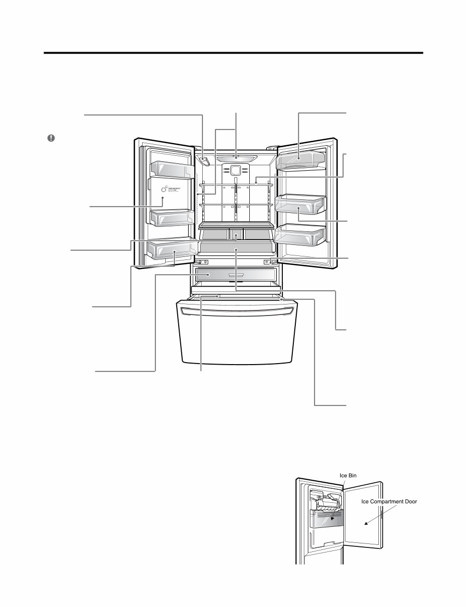
- 4 - 2. PARTS IDENTIFICATION Water filter The water filter purifies water. LED interior lamps The interior lamps light up the inside of the refrigerator. Dairy product bin The dairy product bin is used to preserve dairy products. Adjustable refrigerator shelf The refrigerator compartment shelves are adjustable to allow flexibility for storage needs. Preserve large size food or containers. Modular door bin Interchangeable bins can be arranged to suit your storage needs. Auto closing hinge The refrigerator doors and freezer drawers close automatically when you push them slightly. (The door only closes automatically when it is open at an angle of less than 30°C.) Glide'N'Serve When you want to store food items at a much lower temperature, you can use the temperature controller to maintain the lowest possible chilling temperature (without freezing). F-Basket This is a convenient feature that allows you to fill small frozen food, beverage to needed quick cooling. The filter should be replaced every 6 months. Please refer to°Replacing the filter° in this manual for details. * This function may not be available, depending on the model. Indoor ice bin 100 ice cubes are automatically produced over per 24-hour period. Crisper The crisper controls humidity and helps vegetables and fruit to stay crisp. Fixed door bin The fixed door bin is used to preserve chilled food or drinks that are of a suitable size for storing in this bin. Pull out Drawer It is a convenient feature that allows you to fill large containers such as the extra bin and It is useful to store. Dura Base® Divider This is a convenient feature that allows you to fill large containers, such as an ice chest, cooler or pitcher, with ice. NOTE
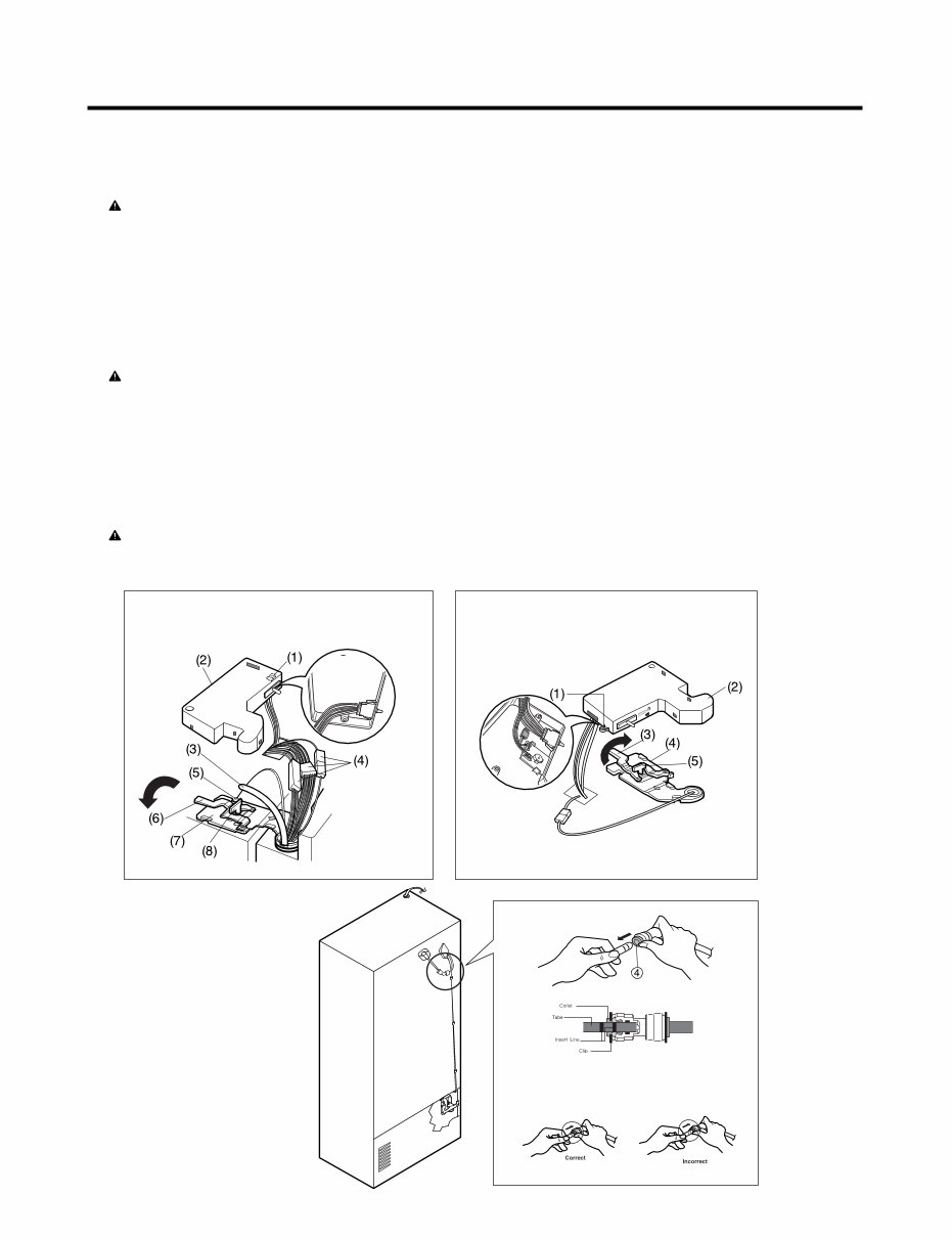
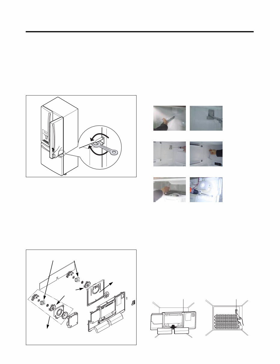
- 5 - 3. DISASSEMBLY 3-1 REMOVING AND REPLACING REFRIGERATOR DOORS ● Removing Refrigerator Door CAUTION: Before you begin, unplug the refrigerator. Remove food and bins from doors. ▶ Left Door -FIG. 2 1. Disconnect water supply tube by pushing back on the disconnect ring (3).-FIG. 1 2. Open door. Loosen top hinge cover screw (1). Use flat tip screwdriver to pry back hooks on front underside of cover (2). Lift up cover. 3. Disconnect door switch wire harness and remove the cover. 4. Pull out the tube. 5. Disconnect all 3 wiring harnesses (4). Remove the grounding screw (5). 6. Rotate hinge lever (6) counterclockwise. Lift top hinge (7) free of hinge lever latch (8). 7. Lift door from middle hinge pin and remove door. 8. Place the door with the insides facing up, on a not scratch surface. CAUTION: When lifting hinge free from the latch, be careful that door does not fall forward. ▶ Right Door -FIG. 3 1. Open the door, remove 1 screw on the top of the hinge cover. Loosen top hinge cover screw (1). Lift up cover (2). 2. Disconnect door switch wire harness and remove the cover. 3. Rotate hinge lever (3) clockwise. Lift top hinge (4) free of hinge lever latch (5). 4. Lift door from middle hinge pin and remove door. 5. Place the door with the insides facing up, on a not scratch surface. CAUTION: When lifting hinge free from the latch, be careful that the door does not fall forward. Figure 2 Figure 3 Figure 1 1) Insert the tube until you can see only one of the lines printed on the tube. 2) After inserting, pull the tube to ascertain that it is secure. 3) Assemble clip.
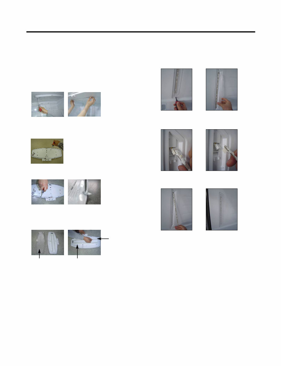
- 6 - 1. Remove gasket Remove the gasket from gasket channel at doorliner as shown in the illustration below. 3-2 DOOR ● Mullion Removal 1. Remove 2 screws. ● Door Gasket Removal 2. Lift mullion up carefully. 3. Disconnect wire harness. ● Door Gasket Replacement 1. Insert gasket into channel Insert and press gasket into channels at doorliner. 2. Insert mullion into channel. Insert the mullion into channel at door as shown below. ● Mullion Replacement 1. Connect wire harness. 3. Assemble 2 screws. Gasket Gasket Channel
- 7 - * Ice Fan Assembly Replacement 1) Remove the plastic guide for slides on left side by unscrewing phillips head screws. 2) Pull out the cover sensor to disassemble by using tools shown in the figure. 3) Pull out the cover grille to disassemble by using tools shown in the figure. 4) Put your hand into the inside of grille to disassemble shown in the figure. 5) Disconnect wire harness of the grille assembly. 6) Remove the Ice fan assembly by loosening all screws. (1) (2) (3) (4) (5) (6) 3-5 DEFROST CONTROL ASSEMBLY Defrost Control assembly consists of Defrost Sensor and FUSE-M. The Defrost Sensor works to defrost automatically. It is attached to the metal side of the Evaporator and senses its temperature. At 46F(8°C), it turns the Defrost Heater off. Fuse-M is a safety device for preventing over-heating of the Heater when defrosting. 1. Pull out the grille assembly. (Figure 1) 2. Separate the connector with the Defrost Control assembly and replace the Defrost Control assembly after cutting the Tie Wrap. (Figure 2) GRILLE ASSEMBLY DEFROST-CONTROL ASSEMBLY 3-3 Door Alignment If the level of refrigerator doors is uneven, follow the instructions below to align the doors: Turn the leveling legs (CCW) to raise or (CW) to lower the height of the front of the refrigerator by using flat blade screw driver or 11/32" wrench. Use the wrench (Included with the User Manual) to adjust the bolt in the door hinge to adjust the height. (CW to raise or CCW to lower the height.) 3-4 FAN AND FAN MOTOR 1. Remove the freezer drawer. 2. Remove the plastic guide for slides on left side by unscrewing phillips head screws. 3. Remove the grille assembly by removing four screws and pulling the grille assembly forward. 4. Remove the Fan Motor assembly by loosening 3 screws and disassembling the shroud. 5. Pull out the fan and separate the Fan Motor and Bracket Motor. FAN MOTOR BRACKET MOTOR Shroud Up Down Ice Fan Assembly
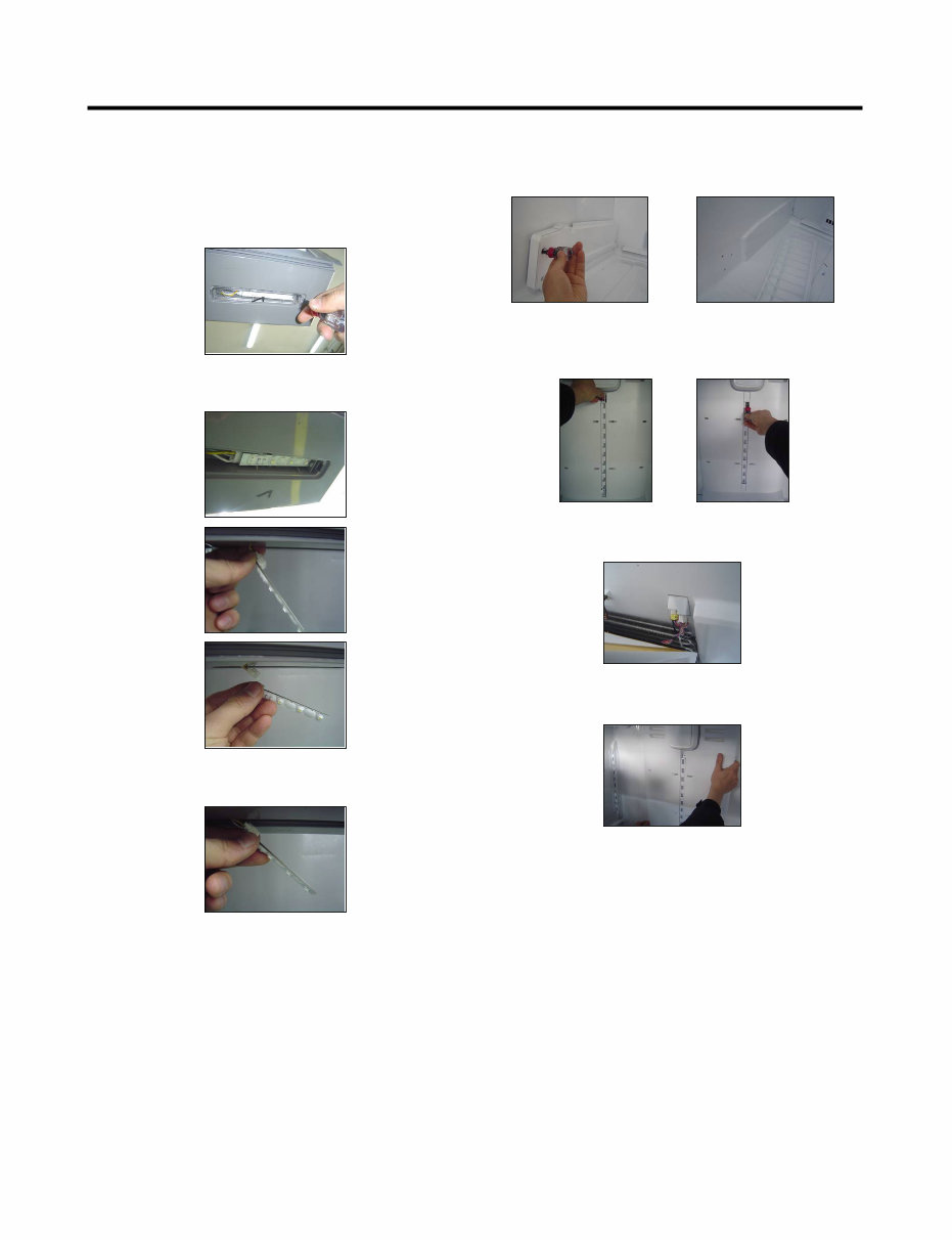
- 8 - 3-6 Refrigerator Light (Top) Unplug Refrigerator, or disconnect power at the circuit breaker. If necessary, remove top shelf or shelves. 1) Release 2 screws. 2) Hold both ends with your both hands and pull it downward to remove it. 3-6-1 Refrigerator Compartment Lamp 4) Use a flat blade screwdriver as shown below to remove the cover lamp. 5) To remove the LED Assembly, open the Hook part to pull it out as shown in the following picture. Cover, lamp Case, lamp LED, Assembly 3) To remove the case lamp and cover lamp, release another 2 screws as following picture. 3-6-2 Refrigerator Light (Side) 1. Unplug refrigerator power cord from electric outlet. 2. Put flat screwdriver into sevice hole and remove cover of refrigerator light. 3. Remove the LED assembly from connector. 4. Replace LED assembly. 5. Assemble the cover in reverse order.
- 9 - 3-7 MULTI DUCT 3-6-3 Cap Duct LED LAMP(Bottom) 1. Unplug refrigerator power cord from electric outlet. 2. Open the refrigerator door to need diassembly. 3. Put flat screwdriver into service hole, remove the cover of cap duct LED LAMP. 5. Replace LED assembly. 6. Assembly the cover in reverse order. 4. Remove the LED assembly from connector. 1. Remove 2 screws and guide rail. 2. Remove the upper and lower Caps by using a flat screwdriver and remove 2 screws as shown figure. 3. Disconnect the lead wire on the bottom position 4. Grip both side of multi duct, pull it out.
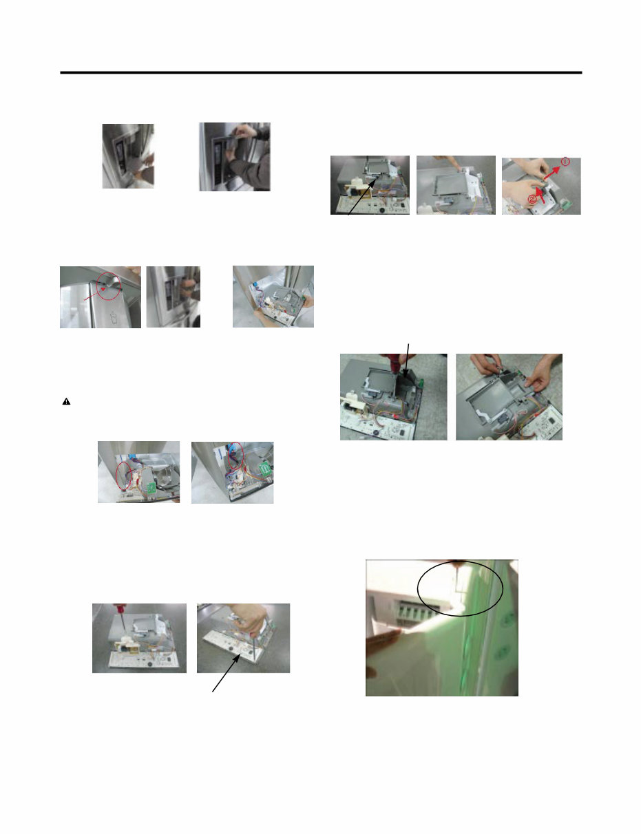
- 10 - 3-12 ICE CORNER DOOR REPLACEMENT 1) Loosen the front screw as shown in the picture. 2) Lift up the hinge with one hand. 3) Pull out the Ice Corner Door with the other hand. 3-11 WATER BUTTON ASSMEBLY 1) Remove screws. 2) Grasp the Button assembly and lift. Button Lever hinge 3-8 DISPENSER 1) Pull out the drain 2) Holding the inner side of the dispenser pull forward to remove. 3-9 DISPLAY PCB As shown below, remove 1 screw on the PCB fixing screw. Remove the display PCB fixing screw. 3-10 ICE BUTTON ASSEMBLY 1) Remove the 1 screw holding the lever. 2) Remove the spring from the hook. 3) Push and pull on the tab to remove. CAUTION: When replacing the dispenser cover make sure the lead wire does NOT come off and the water line is not pinched by the dispenser. Button Lever Case, PCB Display PCB 3) If nozzle is interfered with button, push and pull out the bottom of button. 4) Remove the lead wire.
Is your LG LFX31925ST French Door Refrigerator letting you down?
Why replace while you can upgrade or repair? This service and repair manual is used by the Official Certified LG Technicians. It will help you to troubleshoot and repair your refrigerator!
You will learn about:
Product Specifications
Parts Identification
Disassembly Instructions
Troubleshooting
Adjustment Procedures
Circuit Diagram
Printed Circuit Board
Test Mode & Diagnostics
Operating & Troubleshooting Method of Ice-maker
Description of Function & Circuits
Error Codes
Exploded Views
This service manual is very detailed and illustrated with pictures and step-by-step instructions on how to repair/service this device the best way there is!
Please note; this is the OFFICIAL service and repair manual in .PDF format, no scanned-in or bootlegged copy. This manual is made in the highest resolution, so when you print the pages you need it is all in great quality!
You can easily print this manual from any printer and any computer!
INSTANT access! After your payment, you will have instant access to your access. No shipping fee, no waiting on postal delivery, you can start doing your repairs within minutes!
Specifications
Language: English
Format: .PDF
Pages: 88
Looking for a service manual but can't find it anywhere? Please contact us with your request! As you can see we've got the largest & most comprehensive service manual database out there, so a good chance we can help you out!