CAUTION BEFORE SERVICING THE UNIT, READ THE SAFETY PRECAUTIONS IN THIS MANUAL. REFRIGERATOR SERVICE MANUAL MODELS: LFX2 5975S T LFX25975WB LFX25975SW /01 /01 /01
- 2 - E CN (E ngineering Change Number) LFX25975/01 LocNo. Part Name 410G Capacitor, Electri cApplianceFi lm,Box 304A Cover, PTC 404A Mot or, DC 105A Tube Assembl y, Dra in 329A FanAssembl y 402C Switch,Micro 303B Thermistor Assembl y, PTC 323B Condenser Assembl y, Wire 303A Thermistor Assembl y, PTC 319C Guide, Fan 319A Tra y, Dri p 300A Compre ssor, Set Assembl y
SAFETY PRECAUTIONS ....................................................................................................................................................... 2 1. SPECIFICATIONS............................................................................................................................................................... 3 2. PARTS IDENTIFICATION ................................................................................................................................................... 4 3. DISASSEMBLY.............................................................................................................................................................. 5-14 REMOVING AND REPLACING REFRIGERATOR DOORS ...............................................................................................5 DOOR INSTALLATION ....................................................................................................................................................... 6 DOOR .............................................................................................................................................................................. 7-8 TO REMOVE THE DISPENSER .........................................................................................................................................8 DOOR ALIGNMENT ............................................................................................................................................................8 FAN AND FAN MOTOR(Evaporator) .................................................................................................................................. 8 ICE FAN SCROLL ASSEMBLY REPLACEMENT ..............................................................................................................9 DEFROST CONTROL ASSEMBLY .................................................................................................................................... 9 LAMP .................................................................................................................................................................................. 9 CONTROL BOX-REFRIGERATOR .................................................................................................................................... 9 MULTI DUCT .................................................................................................................................................................... 10 MAIN PWB, DISPLAY PWB REPLACEMENT, FUNNEL REPLACEMENT......................................................................10 SUB PWB FOR DISPENSER, DUCT DOOR REPLACEMENT, ICE CORNER DOOR REPLACEMENT, ICE MAKER ASSEMBLY.......................................................................................................................11 AUGER MOTOR COVER, AUGER MOTOR REPLACEMENT .........................................................................................12 DOOR ICE BIN ..................................................................................................................................................................13 HOW TO REMOVE AND REINSTALL THE PULLOUT DRAWER ...............................................................................14-17 4. ADJUSTMENT............................................................................................................................................................. 18-19 COMPRESSOR ................................................................................................................................................................ 18 PTC-STARTER ................................................................................................................................................................. 18 OLP(OVERLOAD PROTECTOR) ......................................................................................................................................19 TO REMOVE THE COVER PTC .......................................................................................................................................19 5. CIRCUIT DIAGRAM.......................................................................................................................................................... 20 6. TROUBLESHOOTING................................................................................................................................................. 21-25 COMPRESSOR AND ELECTRIC COMPONENTS.......................................................................................................... 21 OTHER ELECTRICAL COMPONENTS ........................................................................................................................... 22 SERVICE DIAGNOSIS CHART ........................................................................................................................................ 23 REFRIGERATION CYCLE .......................................................................................................................................... 24-25 7. OPERATION PRINCIPLE & REPAIR METHOD OF ICEMAKER .............................................................................. 26-28 8. DESCRIPTION OF FUNCTION, CIRCUITS & ERROR CODES..................................................................................29-45 9. EXPLODED VIEW & REPLACEMENT PARTS LIST ..................................................................................................... 46- CONTENTS - 2 - Please read the following instructions before servicing your refrigerator. 1. Unplug the power before handling any elctrical componets. 2. Check the rated current, voltage, and capacity. 3. Take caution not to get water near any electrical components. 4. Use exact replacement parts. 5. Remove any objects from the top prior to tilting the product. SAFETY PRECAUTIONS
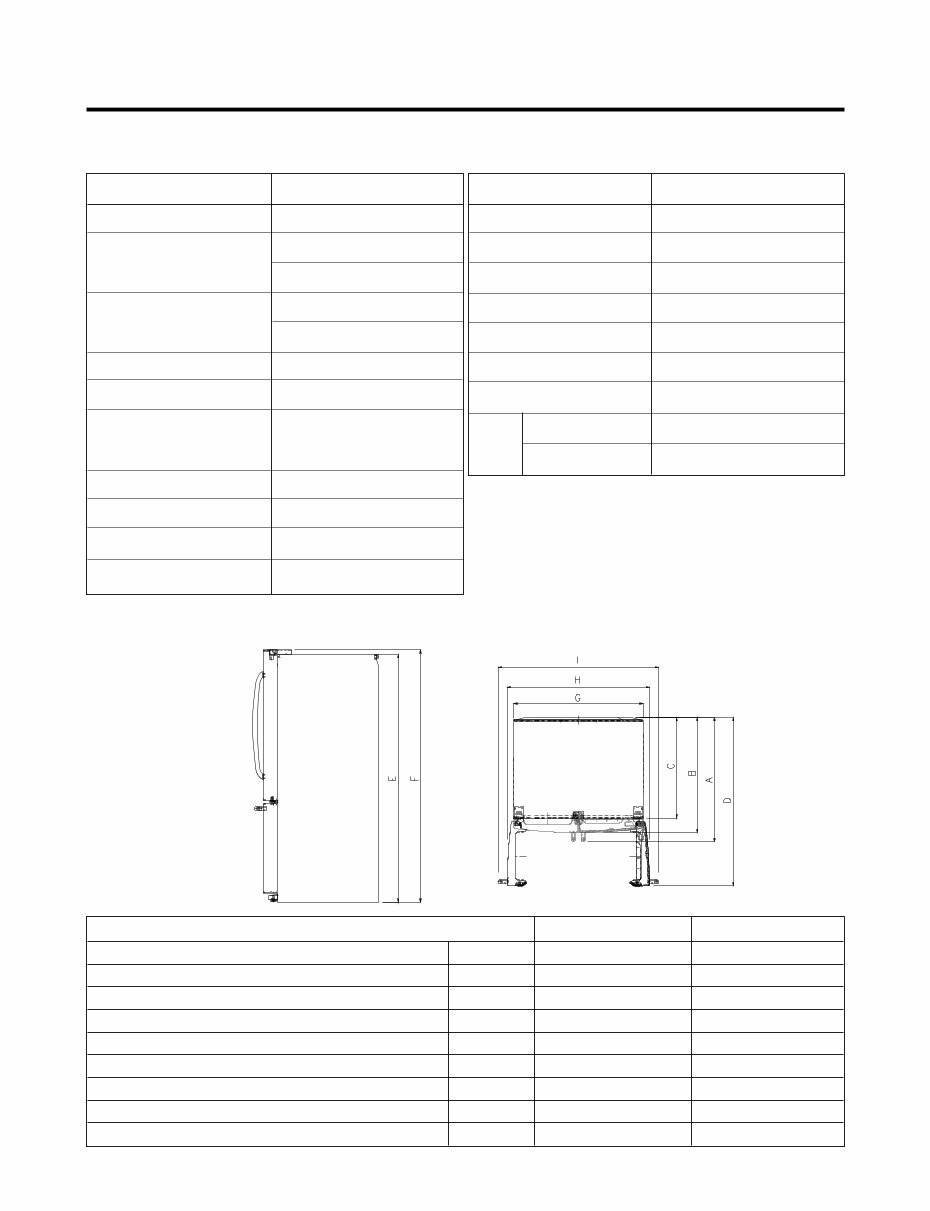
21 cu. ft. / 25 cu. ft. 1. SPECIFICATIONS - 3 - ITEMS SPECIFICATIONS DOOR DESIGN Side Rounded DIMENSIONS (inches) 35 3 / 4 X 30 1 / 4 X 69 3 / 4 (WXDXH) 21cu.ft 35 3 /4 X 34 1 /4 X 69 3 /4 (WXDXH) 25cu.ft NET WEIGHT (pounds) 302.58 (21cu.ft) 324.18 (25cu.ft) COOLING SYSTEM Fan Cooling TEMPERATURE CONTROL Micom Control Full Automatic DEFROSTING SYSTEM Heater Defrost DOOR FINISH Embossed Metal, VCM, Stainless HANDLE TYPE Bar INNER CASE ABS Resin INSULATION Polyurethane Foam ITEMS SPECIFICATIONS VEGETABLE TRAY Opaque Drawer Type COMPRESSOR Recipro EVAPORATOR Fin Tube Type CONDENSER Wire Condenser REFRIGERANT R-134a (145 g) LUBRICATING OIL ISO10 (280 ml) DEFROSTING DEVICE SHEATH HEATER LAMP REFRIGERATOR LED Module(27) FREEZER LED Module(12) Description LFX21975** /01 LFX25975** /01 Depth w/ Handles A 30 in. 34 1/4 in. Depth w/o Handles B 27 1/2 in. 31 3/4 in. Depth w/o Door C 23 5/8 in. 27 7/8 in. Depth (Total with Door Open) D 42 1/4 in. 46 1 /2 in. Height to Top of Case E 68 3/8 in. 68 3/8 in. Height to Top of Door Hinge F 69 3/4 in. 69 3/4 in. Width G 35 3/4 in. 35 3/4 in. Width (door open 90 deg. w/o handle) H 39 1/4 in. 39/1/4 in. Width (door open 90 deg. w/ handle) I 44 1/4 in. 44 1/4 in. DIMENSIONS
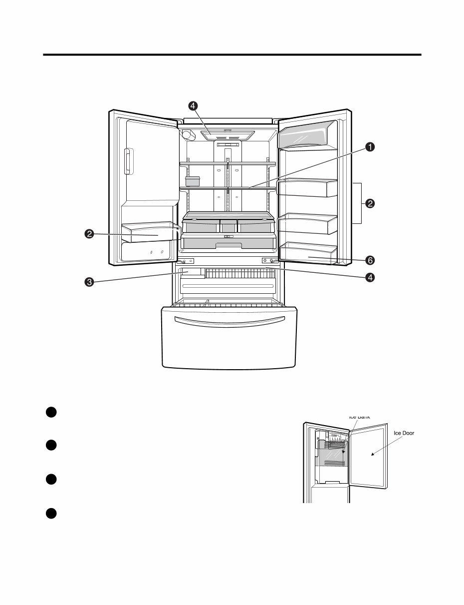
2. PARTS IDENTIFICATION - 4 - ADJUSTABLE REFRIGERATOR SHELVING The refrigerator compartment shelves are adjustable to allow flexibility for storage needs. MODULAR DOOR BINS Three interchangeable bins can be arranged to suit your storage needs. REMOVABLE ICE STORAGE BIN The ice storage bin can be removed to fill ice buckets,coolers,or pitchers. INTERIOR LAMPS Two separate LED arrays light the freezer and refrigerator interiors. 1 2 3 4
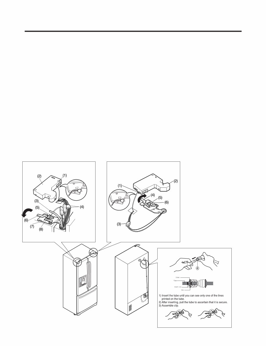
3-1 REMOVING AND REPLACING REFRIGERATOR DOORS ● Removing Refrigerator Door w CAUTION: Before you begin, unplug the refrigerator. Remove food and bins from doors. u Left Door -FIG. 2 1. Disconnect water supply tube by pushing back on the disconnect ring (4).-FIG. 1 2. Open door. Loosen top hinge cover screw (1). Use flat tip screwdriver to pry back hooks on front underside of cover (3). Lift up cover. 3. Disconnect door switch wire harness (2). 4. Pull out the tube. 5. Disconnect the three wire harnesses (5). Remove the grounding screw (6). 6. Rotate hinge lever (7) counterclockwise. Lift top hinge (8) free of hinge lever latch (9). w CAUTION: When lifting hinge free of latch, be careful that door does not fall forward. 7. Place door, inside facing up, down onto a non-scratching surface. u Right Door -FIG. 3 1. Open door. Loosen top hinge cover screw (1). Lift up cover (3). 2. Disconnect door switch wire harness (2). Remove cover. 3. Disconnect wire harness (5). 4. Rotate hinge lever (6) clockwise. Lift top hinge (7) free of hinge lever latch (8). w CAUTION: When lifting hinge free of latch, be careful that door does not fall forward. 5. Lift door up from middle hinge pin (9) and remove door. 6. Place door, inside facing up, down onto a non-scratching surface. 3. DISASSEMBLY - 5 - Correct Incorrect Figure 2 Figure 3 Figure 1
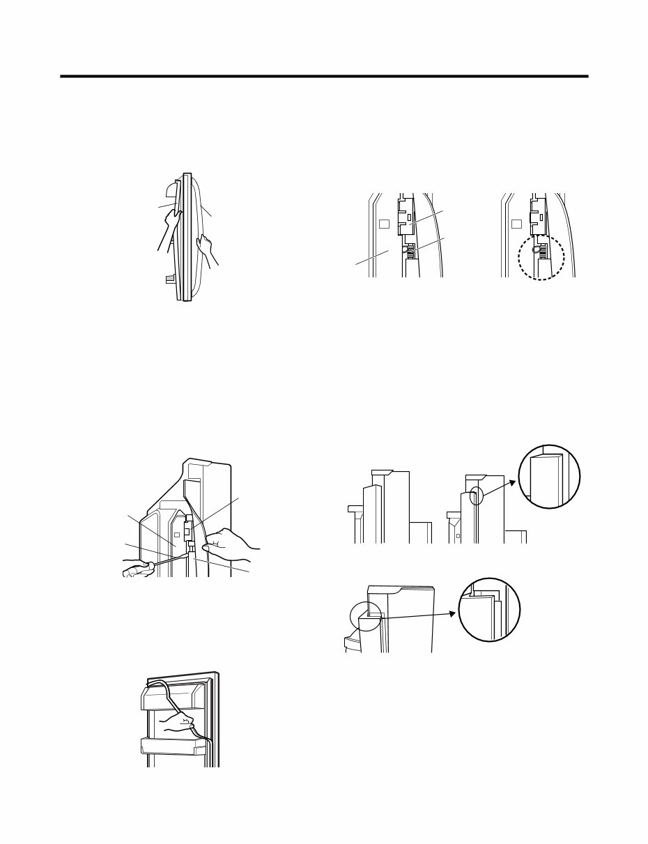
- 6 - 3-2 DOOR ● Door Gasket Removal 1. Remove door frame cover Starting at top of cover and working down, snap cover out and away from door. 2. Remove gasket bracket clips There are two clips on each door. Start bracket removal near one of the middle clips. 1) Pull gasket back to expose gasket bracket clip and door frame. 2) Insert a flat tip screwdriver into seam between gasket bracket and door frame and pry back until clips snap out. 3) Continue prying back along seam until all clips snap out. 3. Remove gasket Pull gasket free from gasket channel on the three remaining sides of door. ● Door Gasket Replacement 1. Insert gasket bracket clips 1) Insert gasket bracket edge beneath door frame edge. 2) Turn upper gasket bracket spring so that the spring ends are in the door channel. 3) Push in clip until you hear it snap securely into place. 4) Push in remaining clip until you hear it snap securely into place. Note: Make sure that no part of gasket bracket edge protrudes from beneath door frame edge. 2. Insert gasket into channel 1) Snap gasket assembly into the door bracket. <Inserting the Gasket Assembly into the Bracket Door> Frame Cover Handle Door Frame Gasket Bracket Clip Flat Tip Screwdriver Gasket Bracket Figure 1 Figure 2 Figure 3 Door Frame Gasket Bracket Clip Spring Incorrect Correct Incorrect Correct Figure 4 Figure 5
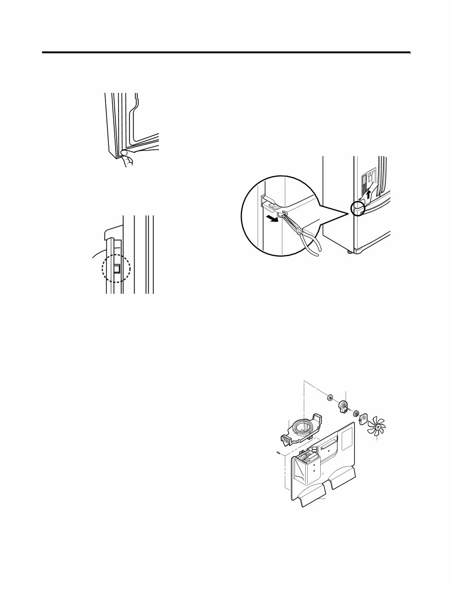
- 7 - 2) Press gasket into channels on the three remaining sides of door. 3. Replace door frame cover Starting at top of cover and working down, snap cover back into door. . 3-4 DOOR ALIGNMENT If the space between your doors is uneven, follow the instructions below to align the doors: 1. With one hand, lift up the door you want to raise at middle hinge. 2. With other hand, use pliers to insert snap ring as shown. 3. Insert additional snap rings until the doors are aligned. (Three snap rings are provided with unit.) 3-5 FAN AND FAN MOTOR(EVAPORATOR) 1. Remove the freezer shelf. (If your refrigerator has an icemaker, remove the icemaker first) 2. Remove the plastic guide for slides on left side by unscrewing phillips head screws. 3. Remove the grille by removing one screw and pulling the grille forward. 4. Remove the Fan Motor assembly by loosening 2 screws and disassembling the shroud. 5. Pull out the fan and separate the Fan Motor and Bracket. Figure 6 Figure 8 Figure 7 GRILLE FAN MOTOR FAN BRACKET MOTOR Figure 9
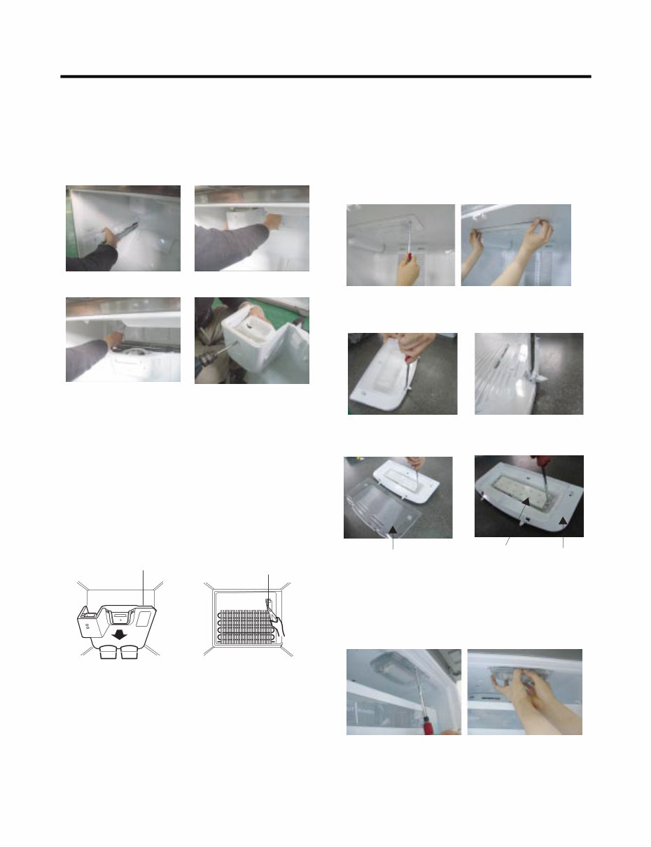
* Ice Fan Scroll Assembly Replacement 1) Remove the plastic guide for slides on left side by unscrewing phillips head screws. 2) Pull the grille forward as shown in the second picture. 3) Disconnect wire harness of the grille 4) Remove the scroll assembly by loosening 2 screws 3-6 DEFROST CONTROL ASSEMBLY Defrost Control assembly consists of Defrost Sensor and FUSE–M. The Defrost Sensor works to defrost automatically. It is attached to the metal side of the Evaporator and senses its temperature. At 72°C, it turns the Defrost Heater off. Fuse-M is a safety device for preventing over-heating of the Heater when defrosting. 1. Pull out the grille assembly. (Figure 10) 2. Separate the connector with the Defrost Control assembly and replace the Defrost Control assembly after cutting the Tie Wrap. (Figure 11) 3-7 LAMP Unplug Refrigerator, or disconnect power at the circuit breaker. If necessary, remove top shelf or shelves. 3-7-1 Refrigerator Compartment Lamp 1) Release 2 screws. 2) Hold both ends with your both hands and pull it downward to remove it. 3) Use a flat tool as shown below to remove the cover lamp. 4) As shown below, use a flat tool to remove the cover lamp. 3-7-2 Freezer Compartment Lamp 1. Unplug refrigerator power cord form outlet. 2. Remove screw with direver. 3. Grasp the cover Lamp,pull the cover downward. - 8 - GRILLE ASSEMBLY Figure 10 DEFROST-CONTROL ASSEMBLY Figure 11 Figure 12 Figure 13 Cover, Lamp Case Lamp LED, Assembly Figure 14 Figure 15 (1) (2) (3) (4)
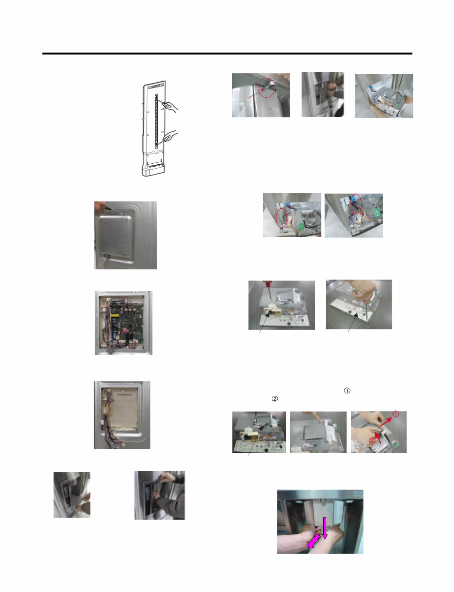
3-8 MULTI DUCT 1. Remove the upper and lower Caps by using a flat screwdriver, and remove 2 screws. (Figure 16) 2. Disconnect the lead wire on the bottom position. 3-9 MAIN PWB 1) Loosen the 3 screws on the PWB cover. 2) Remove the PWB cover 3) Disconnect wire harness and replace the main PWB in the reverse order of removal. 3-10 DISPENSER w CAUTION: When replacing the dispensor cover in the reverse order of removal, be careful that the lead wire does not come out and the water tube is not pinched by the dispensor, 3-11 DISPLAY PCB As shown below, remove 1 case PCB fixing screw. Remove the display PCB fixing screw. 3-12 ICE BUTTON ASSEMBLY 1) Remove the screw fixing the button lever. 2) Push the spring from the hanging hook to remove it. 3) Apply some pressure to the rib in direction and lift the button in direction. 3-13 FUNNEL REPLACEMENT Pull down and forward. Figure 16 Case, PCB Display PCB Button Lever - 9 - 1) Pull out the darin 2) Hold the inner side of cover dispenser with both hands at the handle side to pull it out forward. 3) If nozzle is interfered with button , push and pull out the bottom of button. 4) Rmove the connected part of Lead wire.
Why replace while you can upgrade or repair? This service and repair manual is used by the Official Certified LG Technicians. It will help you to troubleshoot and repair your refrigerator!
You will learn about:
Product Specifications
Parts Identification
Disassembly Instructions
Troubleshooting
Adjustment Procedures
Circuit Diagram
Operation Principle and Repair Method of Ice-maker
Description of Function & Circuits
Exploded Views
This service manual is very detailed and illustrated with pictures and step-by-step instructions on how to repair/service this device the best way there is!
Please note; this is the OFFICIAL service and repair manual in .PDF format, no scanned-in or bootlegged copy. This manual is made in the highest resolution, so when you print the pages you need it is all in great quality!
You can easily print this manual from any printer and any computer!
***INSTANT access*** After your payment, you will have instant access to your manual. No shipping fee, no waiting on postal delivery, you can start doing your repairs right away!
Specifications
Language: English
Format: .PDF
Pages: 53
Platform: Windows and MAC
Looking for a service manual but can't find it anywhere? Please contact us with your request! As you can see we've got the largest & most comprehensive service manual database out there, so a good chance we can help you out!