

LG LFX25778ST Service Manual and Repair Guide
What's Included?
Fast Download Speeds
Online & Offline Access
Access PDF Contents & Bookmarks
Full Search Facility
Print one or all pages of your manual
REFRIGERATOR
SERVICE MANUAL
CAUTION
BEFORE SERVICING THE UNIT,
READ THE SAFETY PRECAUTIONS IN THIS MANUAL.
MODEL :
LFX25778ST
LFX25778SB
LFX25778SW

CONTENTS
- 2 -
1. SPECIFICATIONS .............................................................................................................................................................. 3
2. PARTS IDENTIFICATION .................................................................................................................................................. 4
3. DISASSEMBLY .............................................................................................................................. ................................ 5-17
REMOVING AND REPLACING REFRIGERATOR DOORS ..................................................................................... .......... 5
DOOR .................................................................................................................................................................................. 6
DOOR ALIGNMENT ........................................................................................................................................................... 7
FAN AND FAN MOTOR(EVAPORATOR) ........................................................................................................................... 7
DEFROST CONTROL ASSEMBLY .................................................................................................................................... 7
LAMP .................................................................................................................................................................................. 8
MULTI DUCT ...................................................................................................................................................................... 8
MAIN PWB ........................................................................................................................................................................... 8
DISPENSER ....................................................................................................................................................................... 9
DISPLAY PCB ..................................................................................................................................................................... 9
ICE BUTTON ASSEMBLY ........................................................................................................... ....................................... 9
WATER BUTTON ASSMEBLY ......................................................................................................... ............... 9
ICE COMPARTMENT DOOR REPLACEMENT .............................................................................................. 9
ICEMAKER REPLACEMENT ........................................................................................................................ 10
SUB PWB FOR WORKING DISPENSER ..................................................................................................... 10
CAP DUCT MOTOR REPLACEMENT .......................................................................................................... 11
HOW TO REMOVE THE ICE BIN ................................................................................................................. 12
HOW TO INSERT THE ICE BIN .................................................................................................................... 12
HOW TO REMOVE AND REINSTALL THE PULLOUT DRAWER ................................................................. 13
WATER VALVE DISASSEMBLY METHOD ................................................................................................ .. 16
4. ADJUSTMENT .................................................................................................................................................................. 17
COMPRESSOR ................................................................................................................................................................ 17
5. CIRCUIT DIAGRAM ......................................................................................................................................................... 18
6. TROUBLESHOOTING ...................................................................................................................................................... 19
ERROR CODE SUMMARY ..............................................................................................................................................19
7. OPERATION PRINCIPLE & REPAIR METHOD OF ICEMAKER ............................................................................. . 20-21
MAIN PCB ......................................................................................................................................................................... 20
DISPLAY PCB & SUB PCB .......................................................................................................................... 21
8. TROUBLESHOOTING WITH ERROR DISPLAY .................................................................................... 22-30
9. TROUBLESHOOTING WITH ERROR DISPLAY ........................................................................................................ 31-39
10. REFERENCE ............................................................................................................................................................. 40-43
11. COMPONENT TESTING INFORMATION .............................................................................................. .................. 44-52
12. COMPRESSOR TROUBLESHOOTING ................................................................................................................... 52-63
13. OPERATION PRINCIPLE AND REPAIR METHOD OF ICEMAKER ....................................................................... 64- 65
ICEMAKER’S BASIC OPERATING METHOD ............................................................................................................... 64
ICE MAKER FUNCTIONS .............................................................................................................................................. 65
TROUBLE SHOOTING ICE & WATER SYSTEM ISSUES .................................................................................... ........ 65
14. DESCRIPTION OF FUNCTION & CIRCUIT OF MICOM ............................................................................................... 68
FUNCTION ................................................................................................................................................................68 -70
SAFETY PRECAUTIONS
Please read the following instructions before servicing your
refrigerator.
1. Unplug the power before handling any elctrical
componets.
2. Check the rated current, voltage, and capacity.
3. Take caution not to get water near any electrical
components.
4. Use exact replacement parts.
5. Remove any objects from the top prior to tilting the
product.
15. EXPLODED VIEW ............................................ ..................................................................................................... 72
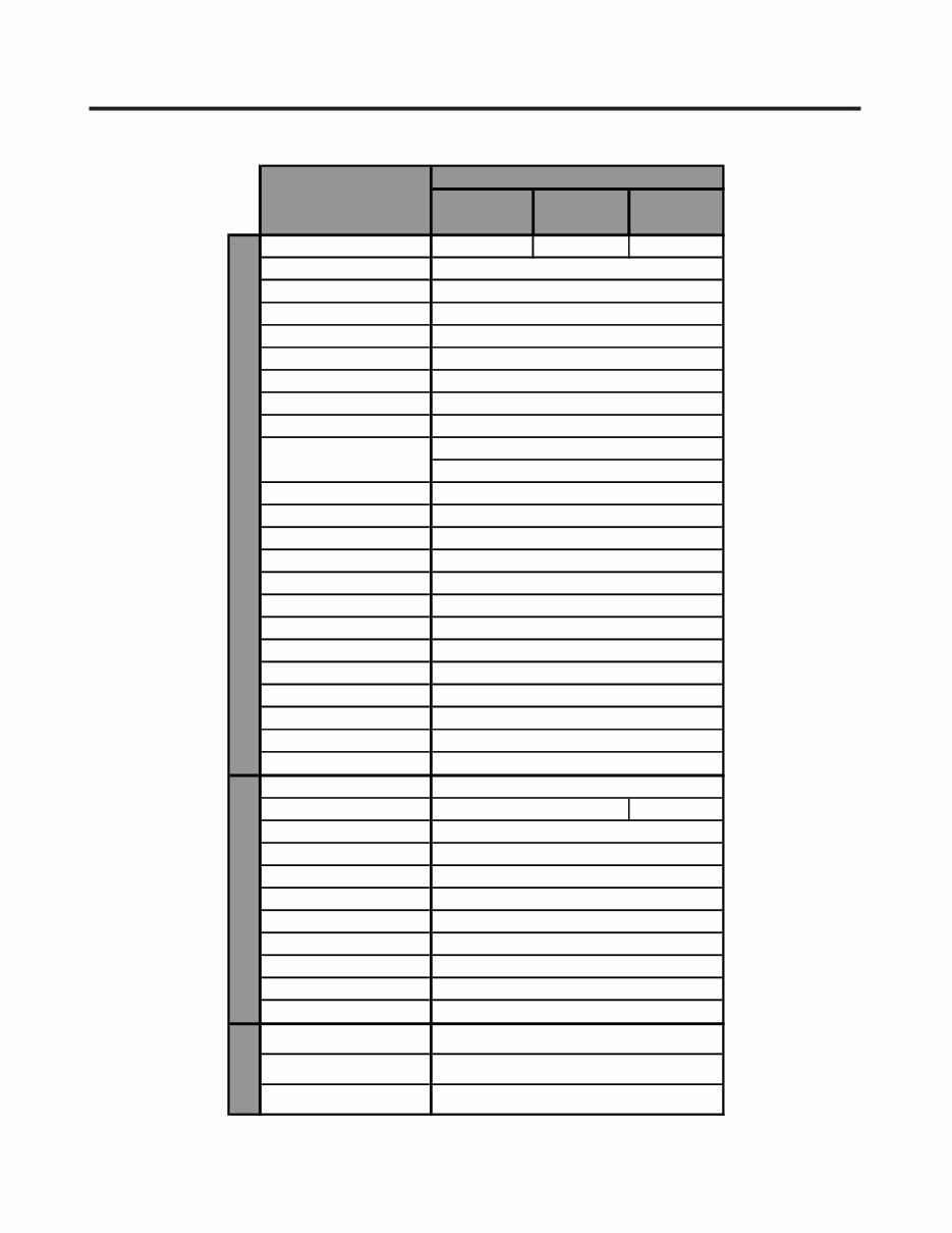
1. SPECIFICATIONS
- 3 -
Color WHITE BLACK STAINLESS
Dimensions (in)
Net Weight (lb)
Capacity
Refrigerant
Climate Class
Rated Rating
Cooling System
Temperature Control
Insulation
Compressor
Evaporator
Condenser
Lubricanting Oil
Drier
Capillary Tube
First Defrost
Defrost Cycle
Defrosting Device
Anti-freezing Heater
Water Tank
Auto ice maker
Case Material
Door material STAINLESS
Handle Type
Display Graphic
Basket
Ice Tray & Bank
Lamp
Shelf
Egg Bank
Pantry
Dairy Corner
Basket
Lamp
Shelf
SHEATH HEATER
YES(1) LED
4EA(fixed)
NO
YES
EMBO
PCM
VISTA
ICE PLUS
PIPE HEATER
YES
IN DOOR ICE MAKER (SLIM)
SPIRAL CONDENSER
CYCLO PENTANANE
LINEAR
ID Ø 0.75
4 HOURS
FREEZER
1 PLASTIC
YES(1) 60W/BLUE
NO
[3 LEFT+3 RIGHT] ( 2gal, 1 half)
AUTO ICE MAKER
REFRIGERATOR
YES(No control)
SPECIFICATIONS
MODELS
LFX25778SW LFX25778SB LFX25778ST
GENERAL FEATURES
32 23/32 X 28 30/32 X 69 3/4 (WXDXH)
313lb
25cu.ft.
R134A
TEMPERATURE (N)
115/60
FAN COOLING
MICOM CONTROL
ISO8 (180 ml)
MOLECULAR SIEVE XH-7
Defrosting System
FULL AUTOMATIC
HEATER DEFROST
7-50 HOURS
FIN TUBE TYPE
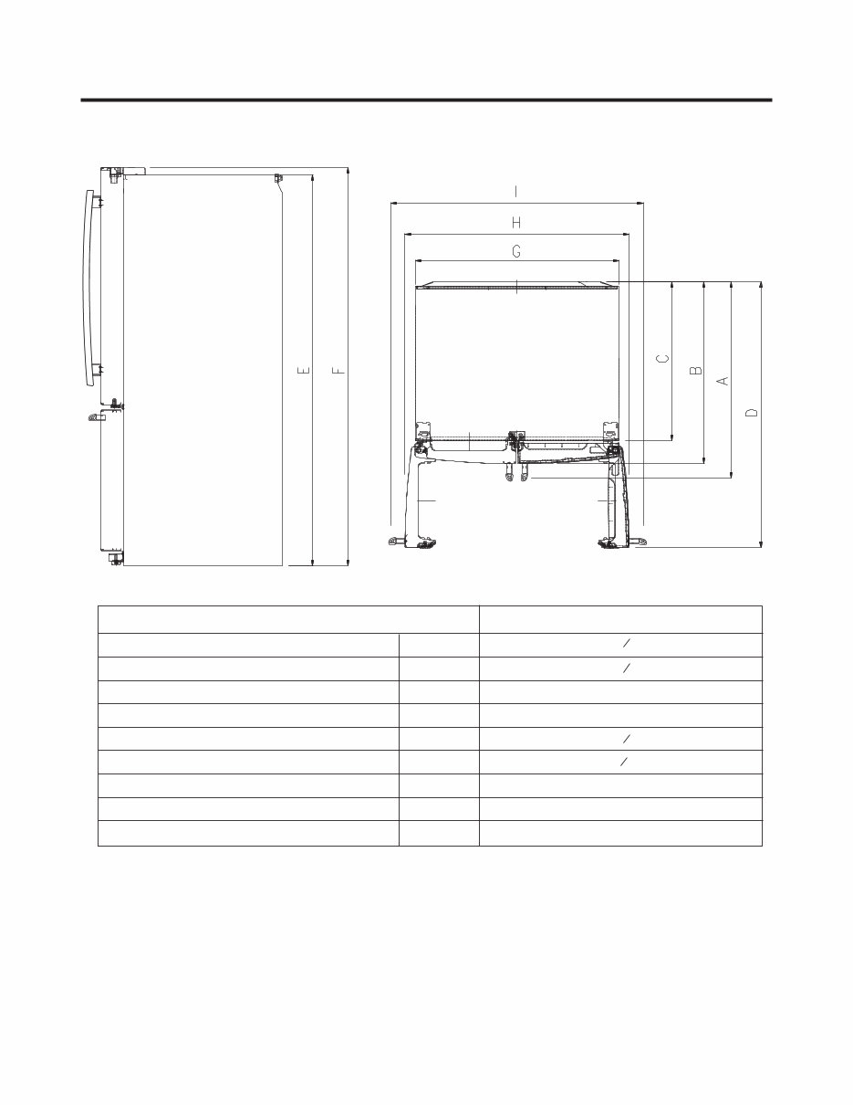
DIMENSIONS
Depth w/ Handles
Depth w/o Handles
Depth w/o Door
Depth (Total with Door Open)
Height to Top of Case
Height to Top of Door Hinge
Width
Width (door open 90 deg. w/o handle)
Width (door open 90 deg. w/ handle)
A
B
C
D
E
F
G
H
I
Description
LFX25778**
29
41 ¼
46 ¼
36 ¼
32 ¾
68
3
8
35
3
8
69
3
4
32
7
8
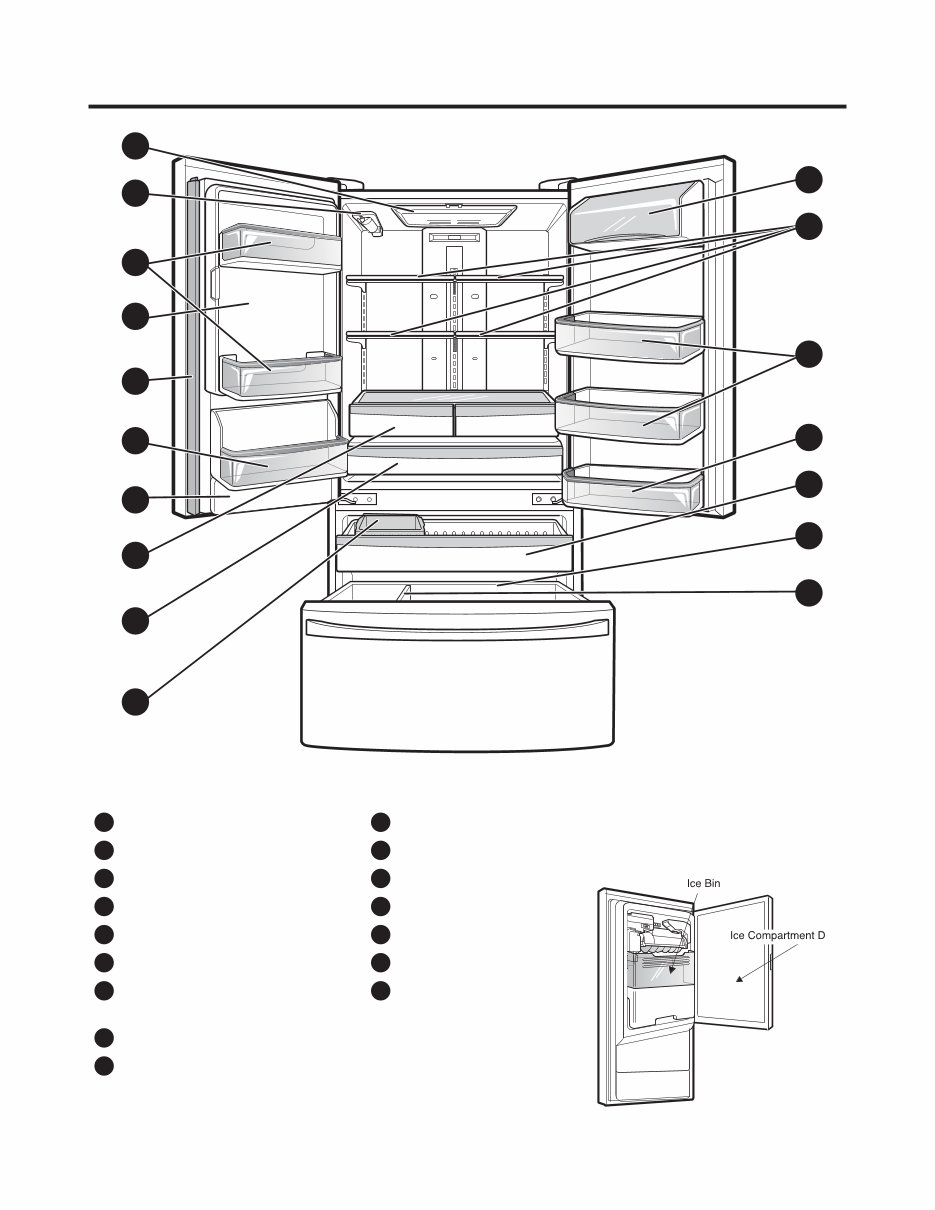
2. PARTS IDENTIFICATION
- 4 -
A
B
G
N
D
Q
P
H
I
J
O
F
C
K
E
L
M
Refrigerator Light
A
Filter (Inside)
B
Modular Door Bins
C
Fixed Door Bin
D
Fixed Door Bin
E
Refrigerator Shelves
F
Ice Room
(Ice Maker and Ice Bin)
G
Pullout Drawer
K
Durabase
L
Divider
M
Door Bins
N
Dairy Bin
O
Water Tank Cover
P
Mullion
Q
Humidity Controlled Crisper
H
Temperature Controlled
Pantry Drawer
I
Extra Ice Bin
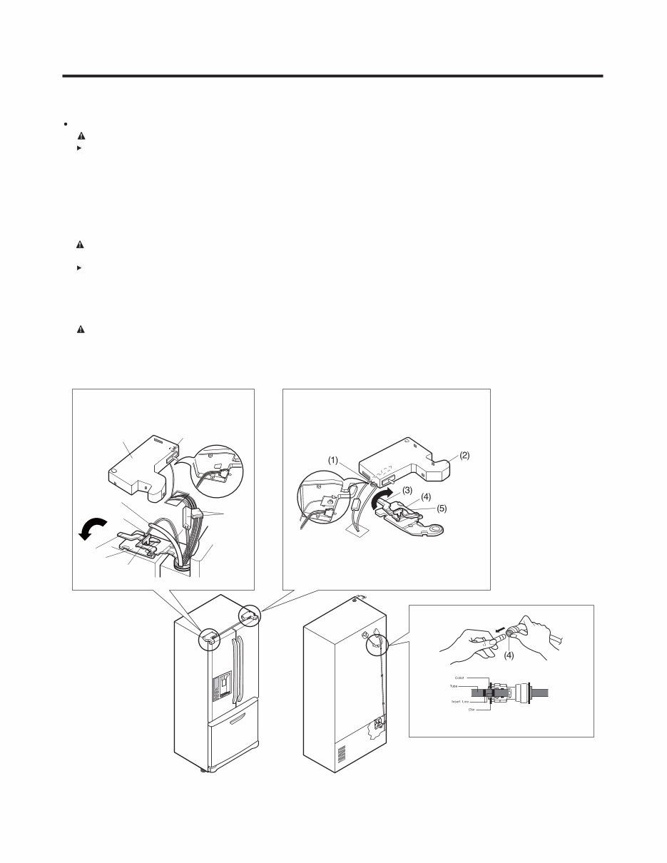
Removing Refrigerator Door
CAUTION : Before you begin, unplug the refrigerator. Remove food and bins from doors.
Left Door -FIG. 2
1. Disconnect water supply tube by pushing back on the disconnect ring (4).-FIG. 1
2. Open door. Loosen top hinge cover screw (1).
Use flat tip screwdriver to pry back hooks on front underside of cover (2). Lift up cover.
3. Disconnect door switch wire harness. Remove cover.
4. Pull out the tube(3).
5. Disconnect the two wire harnesses (4). Remove the grounding screw (5).
6. Rotate hinge lever (6) counterclockwise. Lift top hinge (7) free of hinge lever latch (8).
CAUTION : When lifting hinge free of latch, be careful that door does not fall forward.
7. Place door, inside facing up, down onto a non-scratching surface.
Right Door -FIG. 3
1. Open door. Loosen top hinge cover screw (1). Lift up cover (2).
2. Disconnect door switch wire harness. Remove cover.
3. Rotate hinge lever (3) clockwise. Lift top hinge (4) free of hinge lever latch (5).
4. Lift door from middle hinge pin and remove door.
CAUTION : When lifting hinge free of latch, be careful that door does not fall forward.
5. Place door, inside facing up, down onto a non-scratching surface.
3. DISASSEMBLY
- 5 -
3-1 REMOVING AND REPLACING REFRIGERATOR DOORS
(1)
(2)
(4)
(3)
(6)
(7)
(8)
(5)
Figure 1
Figure 2 Figure 3
- 6 -
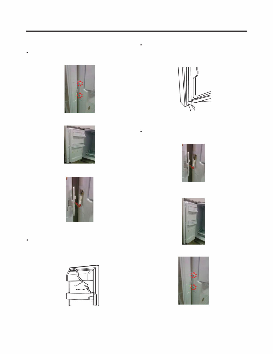
1. Remove gasket
Pull gasket free from gasket channel on the four
remaining sides of door.
3-2 DOOR
Pillar Removal
1. Remove 2 screws.
Door Gasket Removal
2. Lift pillar up carefully.
3. Disconnect wire harness.
Door Gasket Replacement
1. Insert gasket into channel
Press gasket into channels on the four remaining
sides of door.
2. Insert pillar into channel.
Inserting pillar assy’ into bracket, door
Pillar Replacement
1. Connect wire harness.
3. Assemble 2 screws.
- 7 -
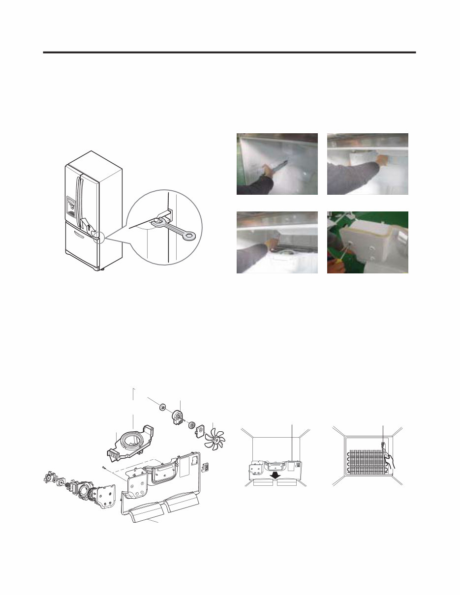
3-3 DOOR ALIGNMENT
If the space between your doors is uneven, follow the
instructions below to align the doors:
Remove the Base Grillie. Turn the leveling legs (CCW) to
raise or (CW) to lower the height of the front of the
refrigerator by using flat blade screw driver or 11/32"
wrench. Use the wrench (Included with the User Manual) to
adjust the bolt in the door hinge to adjust the height. (CCW
to raise or CW to lower the height.)
3-4 FAN AND FAN MOTOR(EVAPORATOR)
1. Remove the freezer shelf.
2. Remove the plastic guide for slides on left side by
unscrewing phillips head screws.
3. Remove the grille by removing one screw and pulling the
grille forward.
4. Remove the Fan Motor assembly by loosening 2 screws
and disassembling the shroud.
5. Pull out the fan and separate the Fan Motor and Bracket.
BRACKET
MOTOR
Ice fan assembly
GRILLE
FAN
FAN MOTOR
* Ice Fan Scroll Assembly Replacement
1) Remove the plastic guide for slides on left side by
unscrewing phillips head screws.
2) Pull the grille forward as shown in the second picture.
3) Disconnect wire harness of the grille.
4) Remove the scroll assembly by loosening all screws.
(3) (4)
3-5 DEFROST CONTROL ASSEMBLY
Defrost Control assembly consists of Defrost Sensor and
FUSE-M.
The Defrost Sensor works to defrost automatically. It is
attached to the metal side of the Evaporator and senses its
temperature. At 46°F (8°C), it turns the Defrost Heater off.
Fuse-M is a safety device for preventing over-heating of the
Heater when defrosting.
1. Pull out the grille assembly. (Figure 4)
2. Separate the connector with the Defrost Control
assembly and replace the Defrost Control assembly after
cutting the Tie Wrap. (Figure 5)
Figure 4 Figure 5
GRILLE ASSEMBLY DEFROST-CONTROL
ASSEMBLY
(1) (2)
- 8 -
Cover, Lamp
LED, Assembly Case Lamp
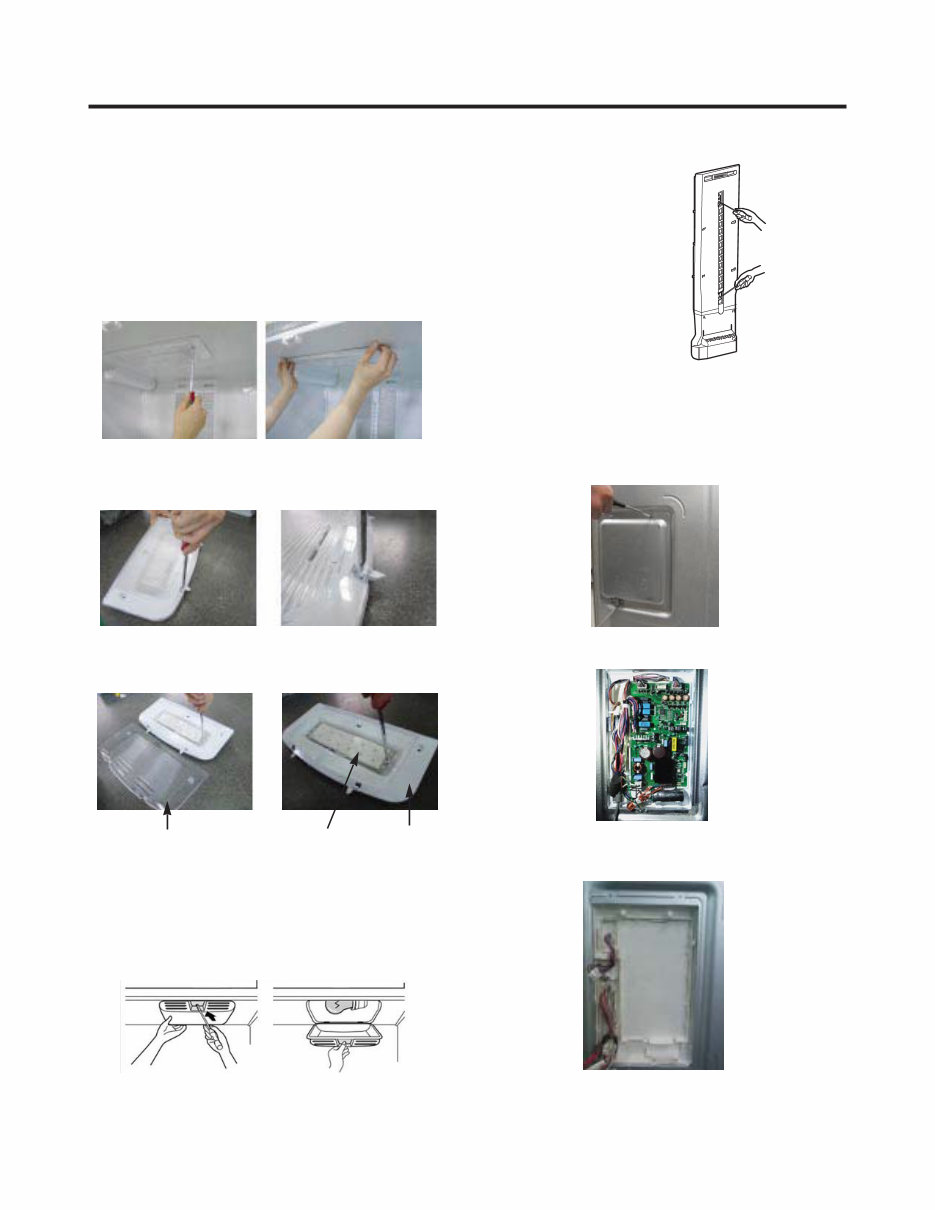
3-6 LAMP
Unplug Refrigerator, or disconnect power at the circuit
breaker.
If necessary, remove top shelf or shelves.
1) Release 2 screws.
2) Hold both ends with your both hands and pull it
downward to remove it.
3) Use a flat tool as shown below to remove the cover
lamp.
3-6-1 Refrigerator Compartment Lamp
1. Unplug refrigerator power cord from outlet.
2. Remove screw with driver.
3. Grasp the cover Lamp, pull the cover downward.
3-6-2 Freezer Compartment Lamp
4) As shown below, use a flat tool to remove the cover
lamp.
3-7 MULTI DUCT
1. Remove the upper and
lower Caps by using a
flat screwdriver, and
remove 2 screws.
(Figure 6)
2. Disconnect the lead wire
on the bottom position.
3-8 MAIN PWB
1) Loosen 3 screws on the PWB cover.
Figure 6
2) Remove the PWB cover
3) Disconnect wire harness and replace the main PWB in
the reverse order of removal.
- 9 -
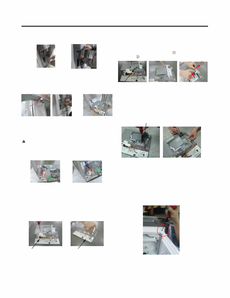
3-9 DISPENSER
1) Pull out the drain 2) Hold the inner side of
cover dispenser with
both hands at the handle
side to pull it out forward.
3) If nozzle is interfered with button,
push and pull out the bottom of
button.
4) Rmove the
connected part
of Lead wire.
3-10 DISPLAY PCB
As shown below, remove 1 case PCB fixing screw.
Remove the display PCB fixing screw.
CAUTION: When replacing the dispensor cover in the
reverse order of removal, be careful that the lead wire
does not come out and the water tube is not pinched by
the dispensor.
Case, PCB Display PCB
3-11 ICE BUTTON ASSEMBLY
1) Remove the screw fixing the button lever.
2) Push the spring from the hanging hook to remove it.
3) Apply some pressure to the rib in direction and lift the
button in direction.
Button Lever
3-13 ICE COMPARTMENT DOOR REPLACEMENT
1) Loosen the front screw as shown in the picture.
2) Lift up the hinge with one hand.
3) Pull out the Ice Compartment Door with the other hand.
3-12 WATER BUTTON ASSMEBLY
1) Romove screws.
2) Grasp the Button assembly and lift up.
Button Lever
hinge
You're Reading a Preview
What's Included?
Fast Download Speeds
Online & Offline Access
Access PDF Contents & Bookmarks
Full Search Facility
Print one or all pages of your manual
$36.99
Viewed 92 Times Today


Secure transaction
What's Included?
Fast Download Speeds
Online & Offline Access
Access PDF Contents & Bookmarks
Full Search Facility
Print one or all pages of your manual
$36.99
Get access to the official factory service, repair, and workshop manual for the LG LFX25778ST French door refrigerator. This comprehensive manual is utilized by Certified LG Technicians and is invaluable for troubleshooting and repairing your refrigerator.
- Product Safety
- Servicing Precautions
- Specifications
- Features & Technical Explanation
- Exploded View
- Troubleshooting Methods
- Error Codes
- Wiring Diagram
- Parts Inspection
- Disassembly Instructions
- Exploded Views
This is the official service manual in PDF format, ensuring high resolution for quality printing. With instant access, there are no shipping fees or waiting on postal delivery, allowing you to commence repairs within minutes.
Specifications:
- Language: English
- Format: PDF
- Pages: 80
Gain access to the same comprehensive manual used by official LG technicians and maintenance employees, guaranteeing the correct execution of repairs, service, and maintenance tasks.


