REFRIGERATOR SERVICE MANUAL CAUTION BEFORE SERVICING THE PRODUCT, READ THE SAFETY PRECAUTIONS IN THIS MANUAL. MODELS : LFC25765ST LFC25765SW LFC25765SB
CONTENTS - 2 - SAFETY PRECAUTIONS Please read the following instructions before servicing your refrigerator. 1. Unplug the power before handling any elctrical componets. 2. Check the rated current, voltage, and capacity. 3. Take caution not to get water near any electrical components. 4. Use exact replacement parts. 5. Remove any objects from the top prior to tilting the product. SAFETY PRECAUTIONS ....................................................................................................................................................... 2 1.SPECIFICATIONS ................................................................................................................ ................................................... 3 2.PARTS IDENTIFICATION .......................................................................................................... ............................................. 4 3.DISASSEMBLY ................................................................................................................... ................................................. 5-9 DOOR ............................................................................................................................................................................... 5-6 DOOR ALIGNMENT ............................................................................................................................................................. 6 HOW TO REMOVE AND REINSTALL THE PULLOUT DRAWER ................................................................................ ... 7-9 4.ADJUSTMENT .................................................................................................................... .................................................. 10 COMPRESSOR ................................................................................................................................................................. 10 5.CIRCUIT DIAGRAM ............................................................................................................... ............................................... 11 6.TROUBLESHOOTING ............................................................................................................... ........................................... 12 ERROR CODE SUMMARY ................................................................................................................................................ 12 7.PCB PICTURE ................................................................................................................... .............................................. 13-14 MAIN PCB .......................................................................................................................................................................... 13 DISPLAY PCB & SUB PCB ............................................................................................................................................... 14 8.TROUBLESHOOTING WITH ERROR DISPLAY .......................................................................................................... 15-22 9.TROUBLESHOOTING WITHOUT ERROR DISPLAY ................................................................................................... 23-28 10.REFERENCE ..................................................................................................................... ............................................... 29-32 11.COMPONENT TESTING INFORMATION .......................................................................................... ........................ 33-41 12.TROUBLESHOOTING ................................................................................................................................................39 -49 13.ICE MAKER AND DISPENSER WORKING PRINCIPLES AND REPAIR ................................................................. 50- 53 14.EXPLODED VIEW & REPLACEMENT PARTS LIST ...................................................................................................... 54
1. SPECIFICATIONS - 3 - Color WHITE BLACK STAINLESS Dimensions (in) Net Weight (lb) Capacity Refrigerant Climate Class Rated Rating Cooling System Temperature Control Insulation Compressor Evaporator Condenser Lubricanting Oil Drier Capillary Tube First Defrost Defrost Cycle Defrosting Device Anti-freezing Heater Water Tank Auto ice maker Case Material Door material STAINLESS Handle Type Display Graphic F, Drawer upper Ice Tray & Bank Lamp Shelf Egg Bank Pantry F, Drawer lower Lamp Shelf GENERAL FEATURES 32 23/32 X 28 30/32 X 69 3/4 (WXDXH) 277 lb 25cu.ft. R134A(125gr) TEMPERATURE (N) 115/60 FAN COOLING MICOM CONTROL ISO8 (180 ml) MOLECULAR SIEVE XH-7 Defrosting System FULL AUTOMATIC HEATER DEFROST 7-50 HOURS FIN TUBE TYPE SPECIFICATIONS MODELS LFC25765SW LFC25765SB LFC25765ST FREEZER 1EA PL+1EA PL BULB NO 1EA PL+1EA PL NO REFRIGERATOR SPIRAL CONDENSER CYCLO PENTANANE LINEAR ID Ø 0.75 4 HOURS SHEATH HEATER HIGH BRIGHTNESS LED 4EA(fixed) NO YES(No control) EMBO PCM VISTA RAPTOR ONLY PIPE HEATER NO TWISTING
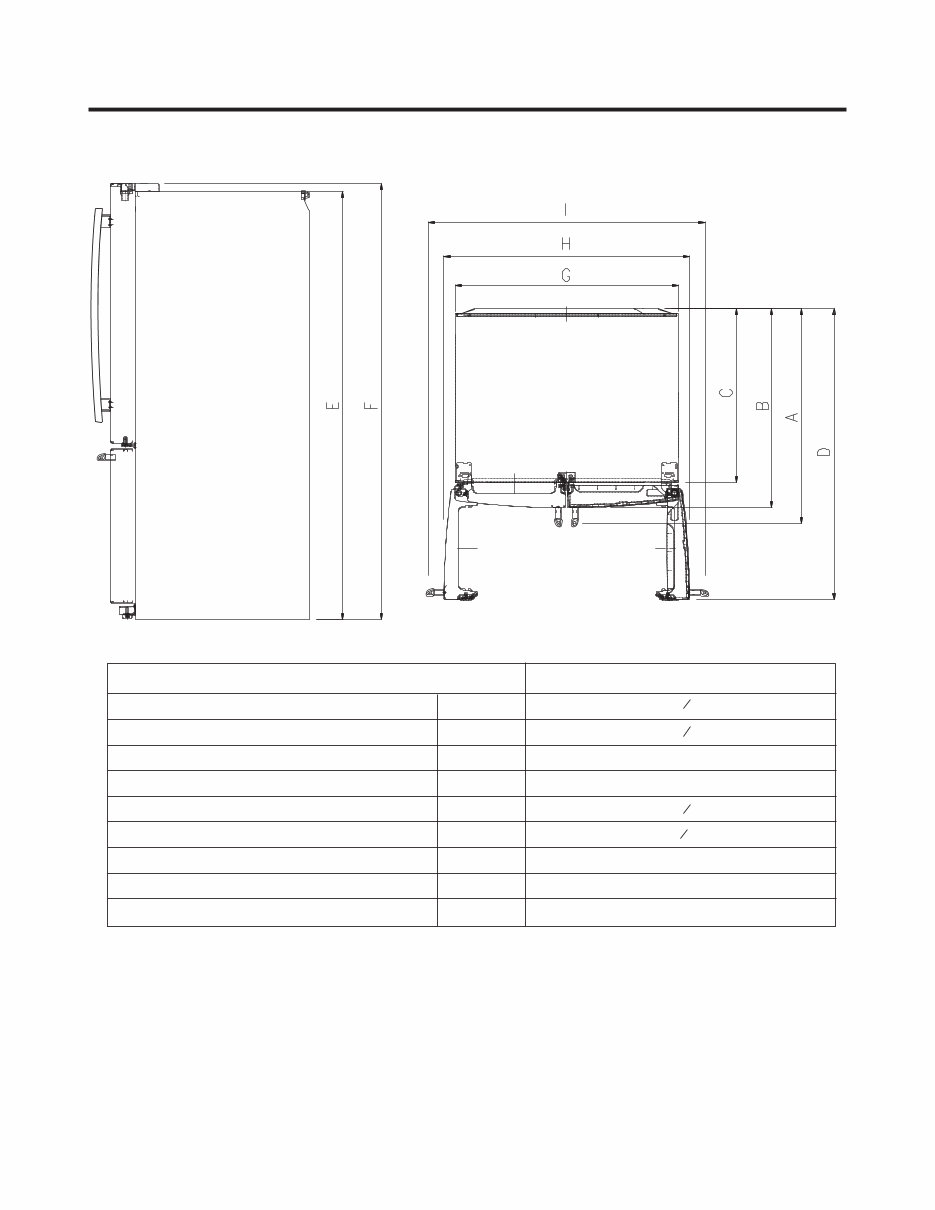
DIMENSIONS Depth w/ Handles Depth w/o Handles Depth w/o Door Depth (Total with Door Open) Height to Top of Case Height to Top of Door Hinge Width Width (door open 90 deg. w/o handle) Width (door open 90 deg. w/ handle) A B C D E F G H I Description LFC25765** 29 41 ¼ 46 ¼ 36 ¼ 32 ¾ 68 3 8 35 3 8 69 3 4 32 7 8
2. PARTS IDENTIFICATION - 4 - Digital Sensor Control Refrigerator Light Shelves Modular Door Bin Glide'N'Serve Ice Bin Durabase Divider Dairy Bin Modular Door Bin Bottle Holder Modular Door Bin Pullout Drawer Optibin Crisper Keeps fruits and vegetable fresh and crisp AUTOMATIC ICEMAKER
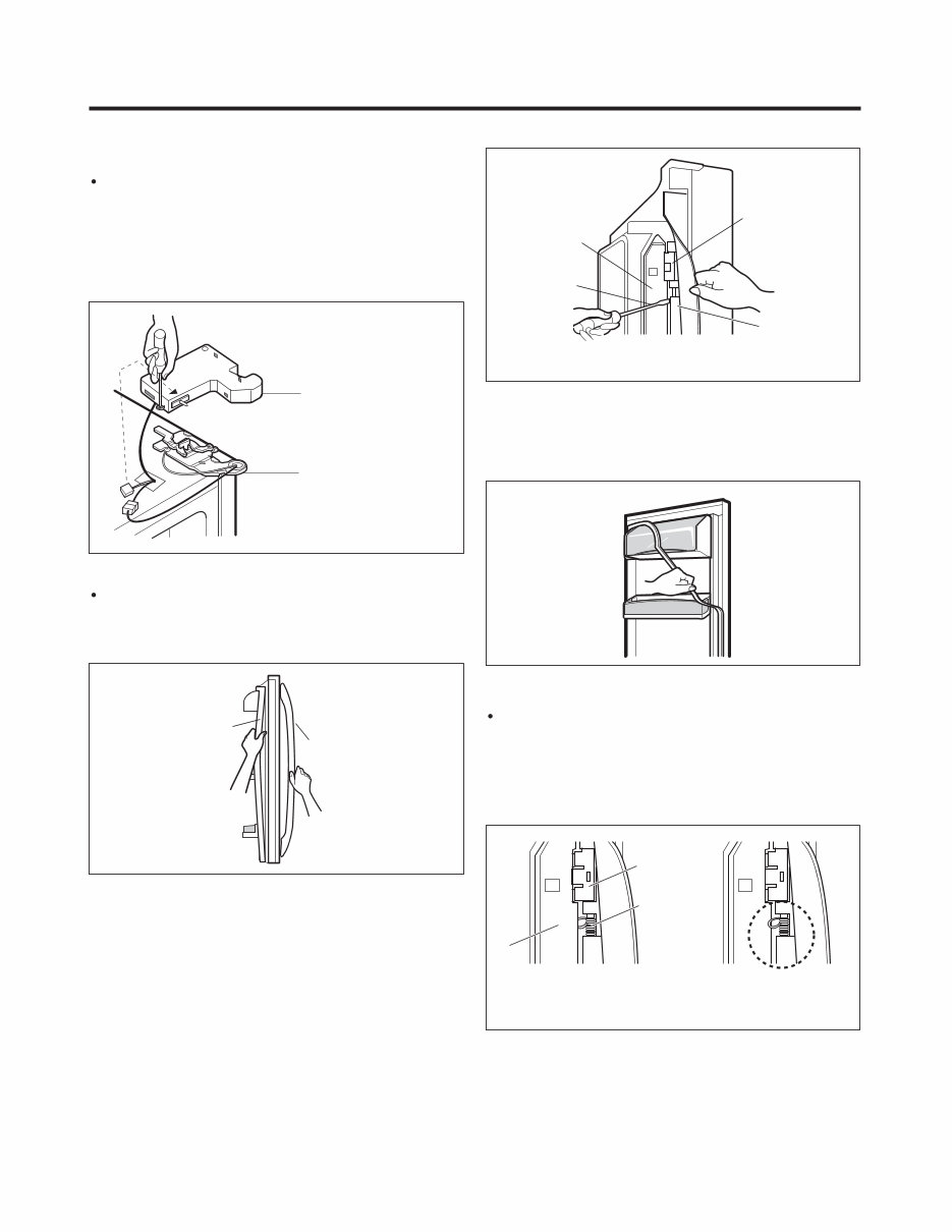
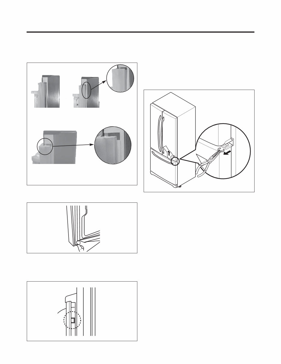
3. DISASSEMBLY - 5 - 3-1 DOOR Refrigerator door 1. Remove the top hinge cover and disconnect the wire harness. 2. Remove the ground screw. 3. Rotate the lever hinge and lift off hinge. 4. Lift off the refrigerator door. 5. Replace in the reverse order. Door gasket replacement 1. Insert gasket bracket clips 1) Insert gasket bracket edge beneath door frame edge. 2) Turn upper gasket bracket spring so that both spring ends are in the door channel. 3) Push in clip until you hear it snap securely into place. 4) Push in remaining two clips until you hear each snap securely into place. Note : Make sure that no part of gasket bracket edge protrudes from beneath door frame edge. 2. Remove gasket bracket clips There are two clips on each door. Start bracket removal near one of the middle clips. 1)Pull gasket back to expose gasket bracket clip and door frame. 2)Insert a flat tip screwdriver into seam between gasket bracket and door frame and pry back until clips snaps out. 3)Continue prying back along seam until all clips snap out. 3. Remove gasket Pull gasket free from gasket channel on the three remaining sides of door. Figure 2 Frame Cover Handle Figure 5 Correct Incorrect Figure 3 Gasket Bracket Clip Gasket Bracket Flat Tip Screwdriver Figure 4 Spring Gasket Bracket Clip Figure 1 HINGE COVER HINGE Door gasket removal 1. Remove door frame cover Starting at top of cover and working down, snap cover out and away from door. Door Frame Door Frame
2. Insert gasket into channel 1) Snap gasket assembly into the door bracket. Inserting the gasket assembly into the bracket door 3. Replace door frame cover Starting at top of cover and working down, snap the cover back into door. 2) Press gasket into channels on the three remaining sides of door. Figure 7 Figure 9 Figure 8 3-2 DOOR ALIGNMENT If the space between your doors is uneven, follow the instructions below to align the doors: 1. With one hand, lift the door you want to raise at middle hinge. 2. With other hand, use pliers to insert snap ring as shown. 3. Insert additional snap rings until the doors are aligned. (Three snap rings are provided with the product.) Correct Figure 6 Incorrect - 6 -
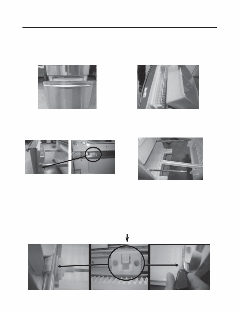
- 7 - 3-3 HOW TO REMOVE AND REINSTALL THE PULLOUT DRAWER 3-3-1 FOLLOW STEPS TO REMOVE Step 1) Open the freezer door. Step 2) Remove the lower basket. Step 3) Remove the two screws from the guide rails (one from each side). Step 5) First : Remove the gear from the left side first by releasing the tab behind the gear, place a screwdriver between the gear and the tab and pull up on the gear. Second : Remove the center rail. Third : Remove the gear from the right side by following the same steps for the left side. NOTE : THIS TAB MUST BE PUSHED IN TO RELEASE THE GEAR. Step 4) Lift the freezer door up to unhook it from the rail support and remove. Pull both rails to full extension.
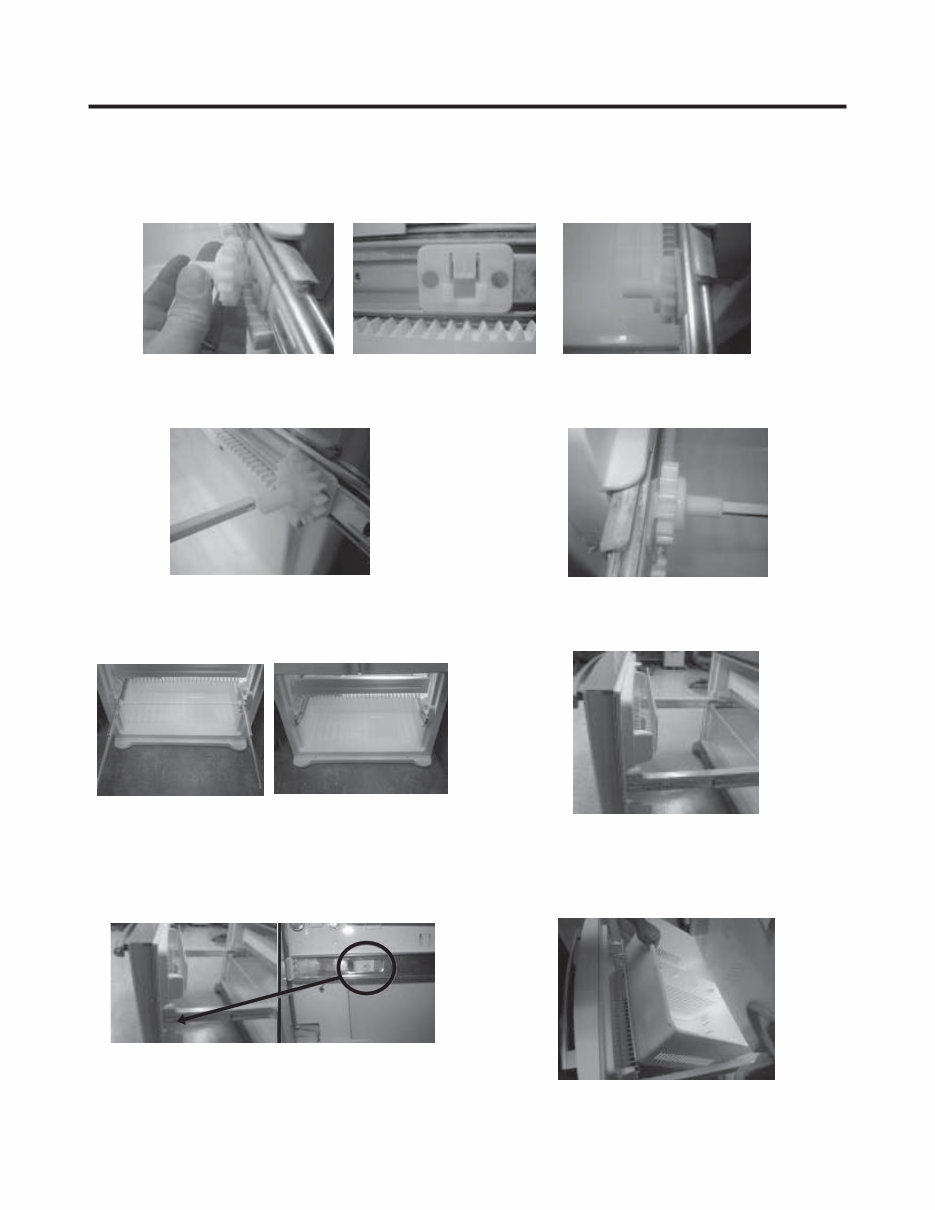
- 8 - 3-3-2 FOLLOW STEPS TO REINSTALL Step 1) Reinstall the right side gear into the clip. Step 2) Insert the rail into the right side gear. Gears do not need to be perpendicular to each other. Step 4) The rail system will align itself by pushing the rails all the way into the freezer section. Pull the rails back out to full extension. Step 5) Reinstall the freezer door by inserting the rail tabs into the guide rail. Step 6) Reinstall the two screws into the guide rails (one from each side). Step 7) Reinstall the lower basket, and close the freezer door. Step 3) Insert the rail into the left side gear, and insert the gear into the clip.
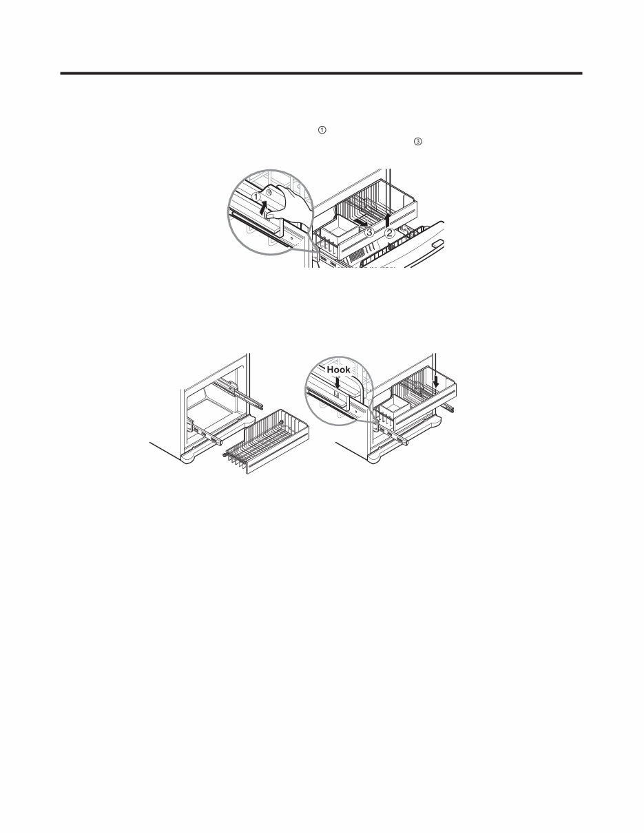
- 9 - 3-3-3 PULL OUT DRAWER To separate the drawer, push the front left and right hooks in direction to pull up and remove. Then gently lift the gear part of rear left and right side of the drawer and pull it out in direction. To install, reposition the gear part of rear left and right side of the drawer after pulling out both rails as much as possible, and gently push down both left and right side while checking the hook on the front part.
Is your LG LFC25765ST Refrigerator letting you down?
Why replace while you can upgrade or repair? This service and repair manual is used by the Official Certified LG Technicians. It will help you to troubleshoot and repair your refrigerator!
You will learn about:
Product Specifications
Parts Identification
Disassembly Instructions
Troubleshooting
Adjustment Procedures
Circuit Diagram
Printed Circuit Board
Test Mode & Diagnostics
Operation Principle and Repair Method of Ice-maker
Description of Function & Circuits
Error Codes
Exploded Views
This service manual is very detailed and illustrated with pictures and step-by-step instructions on how to repair/service this device the best way there is!
Please note; this is the OFFICIAL service and repair manual in .PDF format, no scanned-in or bootlegged copy. This manual is made in the highest resolution, so when you print the pages you need it is all in great quality!
You can easily print this manual from any printer and any computer!
***INSTANT access*** After your payment, you will have instant access to your manual. No shipping fee, no waiting on postal delivery, you can start your repairs right away!