CAUTION BEFORE SERVICING THE UNIT, READ THE SAFETY PRECAUTIONS IN THIS MANUAL. REFRIGERATOR SERVICE MANUAL MODELS: LFC20770SB LFC20770SW LFC20770ST LFC20786SW LFC20786ST LFC20786SB
CONTENTS - 2 - Please read the following instructions before servicing your refrigerator. 1.Check the refrigerator for current leakage. 2.To preven telectric shock,unplug before servicing. 3.Always check line voltage and amperage. 4.Use standard electrical components. 5.Don't touch metal products in the freezer with wet Hands.This may cause frost bite. 6.Prevent water from spiling on to electric elements or the Machine parts. 7.Before tilting the refrigerator,remove all materials from On or in the refrigerator. 8.When servicing the evaporator,wear gloves to prevent Injuries from the sharp evaporator fins. 9.Service on the refrigerator should be performed by a Qualified technician.Sealed system repair must be Performed by a CFC certified technician. SAFETY PRECAUTIONS SAFETY PRECAUTIONS ........................................................................................................ 1. SPECIFICATIONS ............................................................................................................... 2. PARTS IDENTIFICATION .................................................................................................... 3. DISASSEMBLY ................................................................................................................... 3-1 Fan and Fan Motor .......................................................................................................... 3-2 Defrost Control Assembly ................................................................................................. 3-3 LED................................................................................................................................ 3-4 Display .................................................................................................. 3-5 Multiduct.......................................................................................................................... 3-6 Cover Valve...................................................................................................................... 3-7 Door Disassembly ............................................................................................................ 3-8 How to remove the Door Handle..................................................................................... 3-10 How to remove Pull out drawer ..................................................................................... 3-11 Closing and aligning the doors...................................................................................... 4. ADJUSTMENT ................................................................................................................... 4-1 Compressor ................................................................................................................... 4-2 e-PTC-Starter ................................................................................................................ 4-3 OLP (overload protector) ............................................................................................... 6. CIRCUIT DIAGRAM ............................................................................................................ 8. TROUBLESHOOTING ........................................................................................................ 8-1 Compressor and electric components ........................................................................... 8-2 e-PTC and OLP ............................................................................................................. 8-3 Other electrical components .......................................................................................... 8-4 Service diagnosis chart .................................................................................................. 8-5 Refrigeration cycle ......................................................................................................... 5. OPERATION PRINCIPLE AND REPAIR METHOD OF ICEMAKER .................................. 5.1 Operation principle ......................................................................................................... 5.2 Ice maker functions ........................................................................................................ 7. CIRCUIT OF MICOM............................................................................................................ 7.1 Function ......................................................................................................................... 7.2 PCB function .................................................................................................................. 9. EXPLODED VIEW ............................................................................................................... 2 3 4 5 5 5 5 6 6 7 8 10 12 13 16 16 16 17 27 27 28 29 30 31 18 18 19 24 24 26 33 3-9 How to remove the Pillar ................................................................................................. 15 22 8-6 PCB Picture.......... ......................................................................................................... ................................................................................. 8.7 Troubleshooting With Error Display 37 ............................................................................ 8.8 Troubleshooting Without Error Display 58 ............................................................................ 8.9 Appendix.............................................. 81 86
1. SPECIFICATIONS - 3 - Color BLACK WHITE STAINLESS WHITE BLACK STAINLESS Dimensions Net Weight Capacity Refrigerant Climate Class Rated Rating Cooling System Temperature Control Insulation Compressor Evaporator Condenser Lubricanting Oil Drier Capillary Tube First Defrost Defrost Cycle Defrosting Device Anti-freezing Heater Case Material Door material STAINLESS STAINLESS Handle Type VISTA(AL) VISTA(AL) Basket, Quantity Ice Maker Cover , T/V Lamp Shelf Pantry Tray,Egg Basket, Quantity Lamp Tray, drawer F/L Tray, drawer F/U SPECIFICATIONS LFC20770SB LFC20770SW LFC20770ST VISTA(Pl) PCM FREEZER YES (FULL WIDTH) GENERAL FEATURES REFRIGERATOR 3 LEFT+3 RIGHT Defrosting System 2FIX (FULL) INSTALLED READY [(1/B)+(2/T) FAN COOLING MICOM CONTROL FULL AUTOMATIC HEATER DEFROST CYCLO PENTANANE 4 HOURS 7-40 HOURS SHEATH HEATER WATER TRANK HEATER MQ53LAUM PTC STARTING TYPE FIN TUBE TYPE WIRE CONDENSER POLYOL ESTER ISO 10 220+/-10cc MOLECULAR SIEVE XH-7 TEMPERATURE (N) 115 V/60Hz NO YES(1) LED YES (PLASTIC) 4EA(FIXED) HUMIDITY CONTROL YES(1) LED YES NO PCM VISTA(Pl) 3 LEFT+2 RIGHT EMBO ID Ø 0.75 MODELS 29.8(W) x 32.2(D) x 68.4(H) in 111 Kg 20 cu.ft. R134A LFC20786SW LFC20786SB LFC20786ST
DIMENSIONS Depth w/ Handles Depth w/o Handles Depth w/o Door Depth (Total with Door Open) Height to Top of Case Height to Top of Door Hinge Width Width (door open 90 deg. w/o handle) Width (door open 90 deg. w/ handle) A B C D E F G H I Description LFC20770** 28 ¼ 38 ¼ 33 ¼ 32 ¼ 44 29 ¾ 34 ¾ 67 7 16 68 3 16
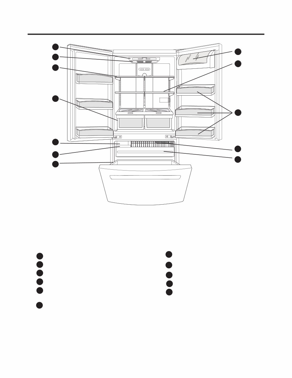
2. PARTS IDENTIFICATION - 4 - Use this section to become more familiar with the parts and features. NOTE: This guide covers several different models. The refrigerator you have purchased may have some or all of the items listed below. The locations of the features shown below may not match your model. * On some models A Digital Sensor Control Dairy Compartment* Door Racks Freezer Light Pull Out Drawer B C D F E G H Durabase I J K Ice Bin Optibin Crisper Keeps fruits and vegetable fresh and crisper Shelves Refrigerator Light (Light Bulb or LED) Ice Maker ** A B C H I F G J J D E K C ** Note: Some models do not include Ice Maker. Ice Maker kit is available for sale. (See about the Automatic Ice maker section)
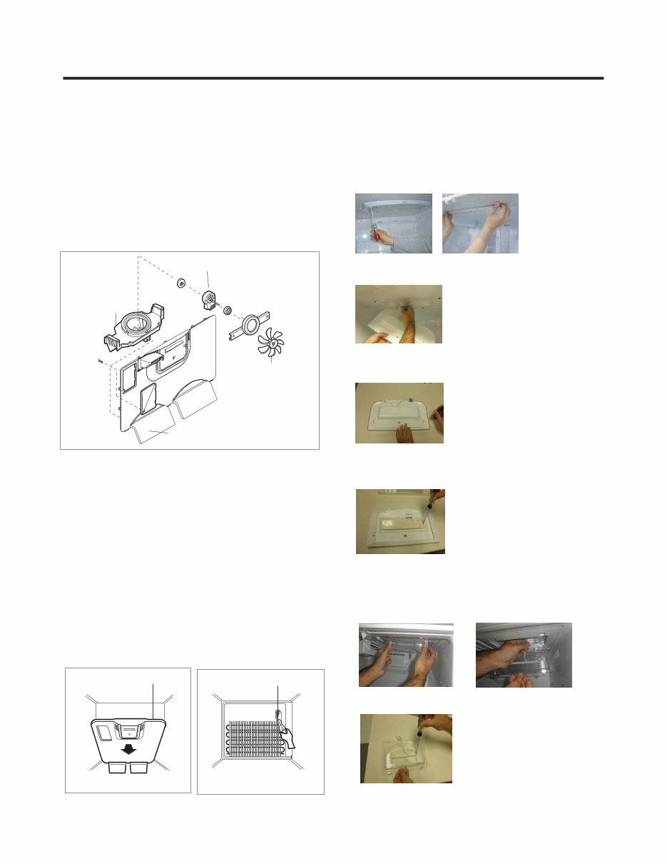
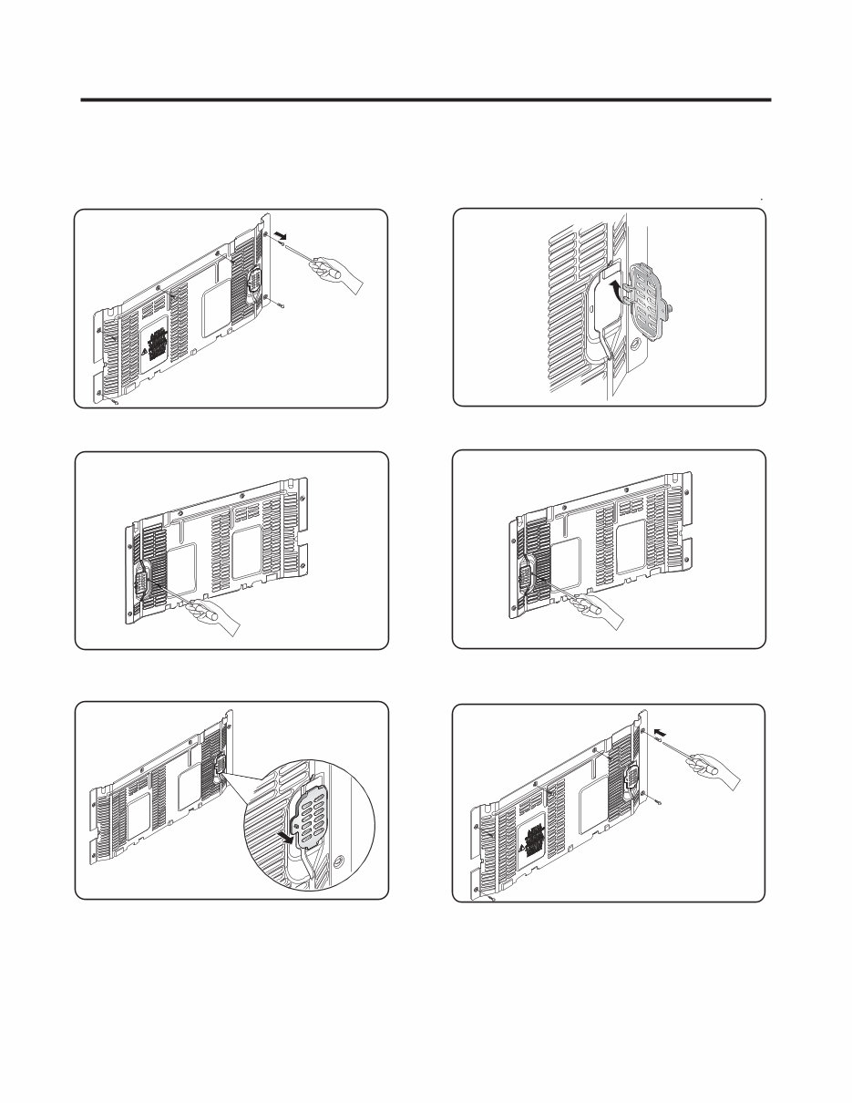
GRILLE ASSEMBLY DEFROST-CONTROL ASSEMBLY GRILLE FAN MOTOR BRACKET MOTOR FAN 3-1 FAN AND FAN MOTOR 1. Remove the freezer shelf. (If your refrigerator has an icemaker, remove the icemaker first). 2. Remove the plastic guide for slides on left side by unscrewing phillips head screws. 3. Remove the grille by removing one screw and pulling the grille forward. 4. Remove the Fan Motor assembly by loosening 2 screw and disassemble the shroud. 5. Pull out the fan and separate the Fan Motor and Bracket. 3-2 DEFROST CONTROL ASSEMBLY Defrost Control assembly consist of Drefrost Sensor and FUSE-M. The Defrost Sensor works to defrost automatically. It is attached to the metal side of the Evaporator and senses its temperature. Fuse-M is safety device for preventing over-heating of the Heater when defrosting. At 72°C, it turns the Defrost Heater off. 1. Pull out the grille assembly. (Fig. 1) 2. Separate the connector with the Defrost Control assembly and replace the Defrost Control assembly after cutting the Tie Wrap. (Fig. 2) 3-3 LED 3-3-1 REFRIGERATOR COMPARTMENT LAMP 3-3-2 FREEZER COMPARTMENT LAMP Fig. 1 Fig. 2 3. DISASSEMBLY - 5 - Unplug, or disconnect power at the circuit breaker. If necessary, remove top shelf or shelves. 1)Release 2 screws. 2)Hold both ends and pull down to remove. 4)Use a flat tool as shown below to remove the lamp cover. 5)To remove the LED assembly, pull apart the cover and 3) Remove LED connector release the 2 screws. 1. Unplug refrigerator power cord form outlet. 2. Pull down the cover Lamp y r emove LED connector 3) Release 2 srews to remove LED.
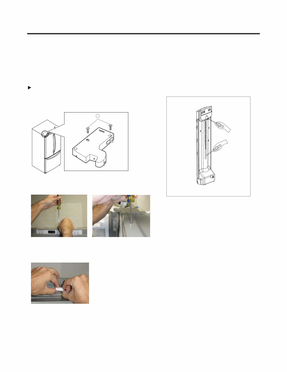
3-5 MULTI DUCT 1. Remove an upper and lower Cap by using a flat 2. Disconnect the lead wire on the botton position. - 6 - 3-4 DISPLAY 1. To disassemble, remove the cover hinge from any door. IMPORTANT: Before you begin,unplug your refrigerator. Left Door Release the two screws from the upper lid (1) remove it after that. 1 2.Whit a screwdriver, remove the screw from Display. 3.Unplug the connector. screwdriver, and loosen 2 screws. NOTE: To assemble, follow the instruction above, at inverse order.
3-6 VALVE COVER (in some models) 3-6-1 DISASSEMBLE 3-6-2 ASSEMBLE 1. Unscrew the back cover. 2. Unscrew the valve from the back side. cover 3. Push to the left and release. 1. Insert the ribs to the right side of the back hole cover 2. Screw the valve from the back side. cover 3. Screw the back . cover - 7 -
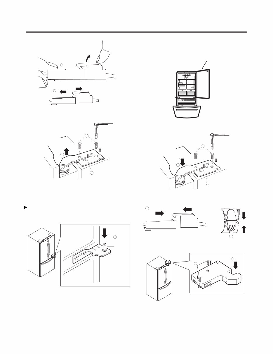
1. To remove Refrigerator door 3-7 DOOR DISASSEMBLY IMPORTANT: Before you begin, turn the refrigerator OFF and Unplug it. Remove all food and the shelves from the doors. Left Door Right Door NOTE: The appearance of the handle might be different. With the Philips screw driver, loose the two screws from the upper lid (1) remove it after that. 1 2 With the 10mm socket wrench, loose the two pins from the hinge (3) and remove it (4). 3 4 Unplug the switches cable (2) it’s optional, it’s no neccesary do it for removing the door. Place the door with the inner face over the surface so it won't scratch. 5 Unplug the switches cable (6) it’s optional, it’s no neccesary do it for removing the door. 6 Unplug the cable harness pulling up the hook located in the upper part of it (7) and separate both parts of the Upper view of the harness harness (8). - 8 -
Loose the grounding screw (9) and the pins (10) located over the hinge, after, lift the hinge and remove it (11). 8 Remove the door and place it over its inner face to avoid scratching. Right Door Take the door and place it gently over the pin of the 1 Pin Check that the sealing patch of the door is leveled to the refrigerator and that it isn´t bended. 9 10 11 hinge (1). 7 Front view of the harness Place the hinge in its original position (4) assembly the two pins (5) and the ground screws (6). Plug the cable harness (7) and the switch (8) (just in case 7 8 4 5 6 Right Door if you unplugged the switch). Place the hinge lid (9) and install both screws (10). Be sure the door is correctly assembled. 9 10 2. To install Refrigerator door - 9 -
Are you experiencing issues with your LG LFC20770ST Refrigerator? Don't rush to replace it – consider upgrading or repairing it instead! This comprehensive service and repair manual is utilized by Official Certified LG Technicians and will assist you in troubleshooting and fixing your refrigerator.
Within this manual, you will gain insights into product specifications, parts identification, disassembly instructions, troubleshooting, adjustment procedures, circuit diagram, printed circuit board, test mode & diagnostics, operation principle and repair method of ice-maker, description of function & circuits, error codes, and exploded views.
Featuring detailed illustrations and step-by-step instructions, this service manual provides the best approach to repairing and servicing the device. It is the official manual in .PDF format, ensuring high-resolution quality for printing on any computer and printer.
With instant access upon payment, there are no shipping fees or waiting for postal delivery – you can commence your repairs immediately. The manual is available in English and comprises 94 pages.