MODELS: LDC22720SW /03 LDC22720ST /03 LDC22720TT /03 LBC22520SW /03 LBC22520SB /02 CAUTION BEFORE SERVICING THE UNIT, READ THE SAFETY PRECAUTIONS IN THIS MANUAL. REFRIGERATOR SERVICE MANUAL
CONTENTS - 2 - SAFETY PRECAUTIONS ........................................................................................................ 1. SPECIFICATIONS ............................................................................................................... 2. PARTS IDENTIFICATION .................................................................................................... 2-1 Freezer Drawer Model..................................................................................................... 2-2 Freezer Swing Model....................................................................................................... 3. DISASSEMBLY ................................................................................................................... 3-1 Fan and Fan Motor .......................................................................................................... 3-2 Defrost Control Assembly ................................................................................................. 3-3 Lamp................................................................................................................................ 3-4 Control Box Refrigerator .................................................................................................. 3-5 Multiduct.......................................................................................................................... 3-6 Cover Valve...................................................................................................................... 3-7 Door Disassembly for Drawer Type Models..................................................................... 3-7-1 Remove Drawer Refrigerator Door ......................................................................... 3-7-2 Replace Drawer Refrigerator Door ......................................................................... 3-7-3 Reverse Drawer Refrigerator Door ......................................................................... 3-7-4 Pull out Drawer ....................................................................................................... 3-7-5 How to Reverse Drawer Door Handle.................................................................... 3-8 Door Disassembly for Swing Type Models...................................................................... 3-8-1 Remove Swing Refrigerator and Freezer Doors.................................................... 3-8-2 Replace Swing Refrigerator and Freezer Doors.................................................. 3-8-3 Reverse Swing Refrigerator and Freezer Doors.................................................... 3-8-4 How to Reverse Swing Door Handle...................................................................... 3-9 After completing the job................................................................................................... 3-10 Leveling and door closing.............................................................................................. 3-11 Door alignment............................................................................................................... 4. ADJUSTMENT .................................................................................................................... 4-1 Compressor ................................................................................................................... 4-2 PTC-Starter .................................................................................................................... 4-3 OLP (overload protector) ............................................................................................... 5. CIRCUIT DIAGRAM ............................................................................................................ 6. TROUBLESHOOTING ........................................................................................................ 6-1 Compressor and electric components ........................................................................... 6-2 PTC and OLP ................................................................................................................. 6-3 Other electrical components .......................................................................................... 6-4 Service diagnosis chart .................................................................................................. 6-5 Refrigeration cycle ......................................................................................................... 3 4 5 5 6 7 7 7 7 8 8 9 10 10 10 11 13 15 16 16 17 18 22 23 23 23 24 24 24 25 26 27 27 28 29 30 31
- 3 - 7. OPERATION PRINCIPLE AND REPAIR METHOD OF ICEMAKER .................................. 7-1 Operation principle ......................................................................................................... 7-2 Ice maker functions ........................................................................................................ 8. CIRCUIT OF MICOM............................................................................................................ 8-1 Function ......................................................................................................................... 8-2 PCB function .................................................................................................................. 8-3 Resistance specification of sensor ................................................................................ 10. EXPLODED VIEW AND REPLACEMENT PART LIST...................................................... 33 33 34 37 37 41 45 46 SAFETY PRECAUTIONS Please read the following instructions before servicing your refrigerator. 1.Check the refrigerator for current leakage. 2.To prevent electric shock,unplug before servicing. 3.Always check line voltage and amperage. 4.Use standard electrical components. 5.Don't touch metal products in the freezer with wet hands.This may cause frost bite. 6.Prevent water from spiling on to electric elements or the machine parts. 7.Before tilting the refrigerator, remove all materials from on or in the refrigerator. 8.When servicing the evaporator, wear gloves to prevent injuries from the sharp evaporator fins. 9.Service on the refrigerator should be performed by a qualified technician.Sealed system repair must be performed by a CFC certified technician.
1. SPECIFICATIONS - 4 - LDC22720SW LDC22720ST LDC22720TT LBC22520SW LBC22520ST Super White Stainless Titanium Super White Stainless PCM Stainless VCM PCM Stainless 892 (W) x 915 (D) x 1840 (H) in 107.7 Kg IB/(1EA) No Plastic (1) Yes No 116.5 Kg MICOM control Fan Cooling 115V~ / 60Hz Temperate (N) R134a 22 cuft MC57LAUM PTC Starting Type Cyclo, Pentane Heater Defrost Full Automatic MODELS SPECIFICATIONS Capacity Refrigerant Net Weight Dimensions GENERAL FEATURES Color Cooling System Rated Rating Climate class Defrost Cycle Defrosting System Insulation Compressor Drier Temperature Control Evaporator First Defrost Condenser Lubricanting Oil MOLECULAR SIEVE XH-7 ID Ø0.75 4 Hours Capillary Tube Polyol Ester (POE) ISO 10 220±10cc Wire Condenser Fin Tube Type Heater, Sheath Water Tank Heater Embo (normal) 7 - 40 Hours Vista ICE PLUS 2 1/3+ 2 2/3 + 1 Full REFRIGERATOR Case Material Door Material Handle Type Display Graphic Egg Bank Lamp FREEZER Basket, Quantity Tray meat Ice Tray & Bank Basket, Quantity Anti-freezing Heater Shelf Desfrosting Device Lamp Shelf Yes (2) 40W/Blue 4 Fix Yes Yes (1) 40W/Blue No Wire (1)
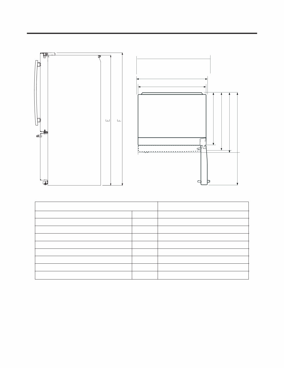
Depth w/ Handles Depth w/o Handles Depth w/o Door Depth (Total with Door Open) Height to Top of Case Height to Top of Door Hinge Width Width (door open 90 deg. w/o handle) Width (door open 90 deg. w/ handle) A B C D E F G H I Description C I H G B A D DIMENSIONS 34 7/16 LDC22720** 31 15/16 28 3/16 61 15/16 67 11/16 68 3/8 32 3/4 34 1/8 36 5/8
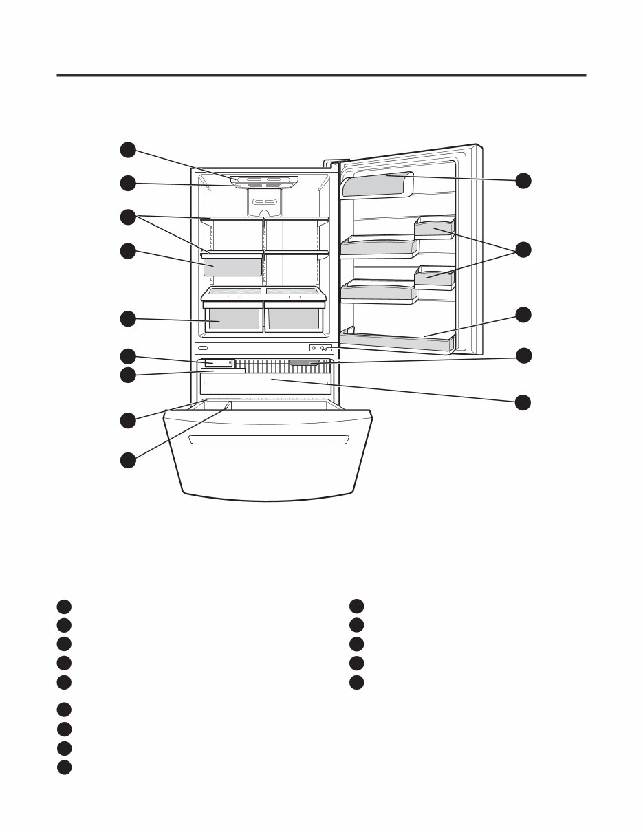
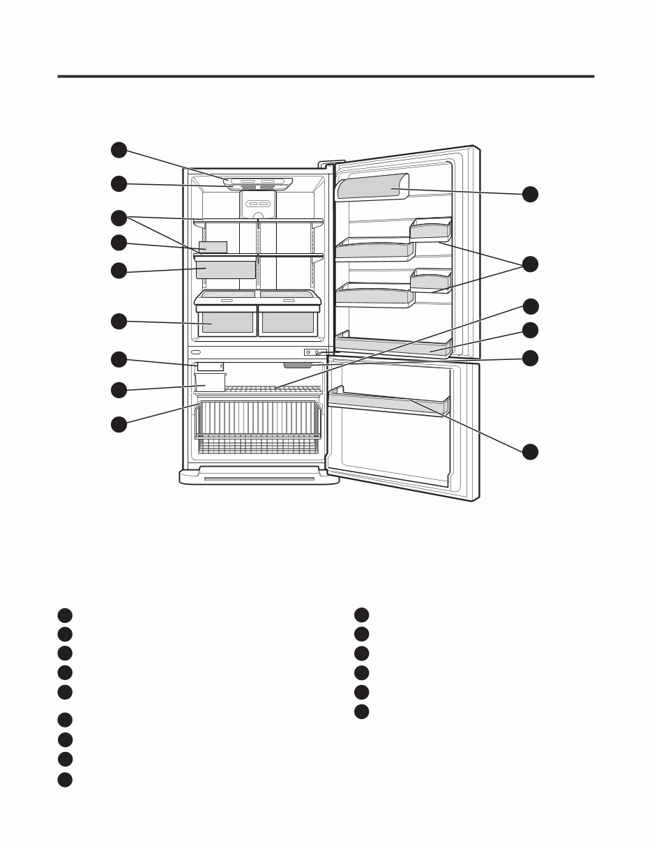
2-1 FREEZER DRAWER MODEL 2. PARTS IDENTIFICATION - 5 - Use this section to become more familiar with the parts and features. NOTE: This guide covers several different models. The refrigerator you have purchased may have some or all of the items listed below. The locations of the features shown below may not match your model. Digital Sensor Control Refrigerator Light Shelves Snack Pan Optibin Crisper Keeps fruits and vegetable fresh and crisp Ice Bin Durabase Dairy Bin Door Bins Refrigerator Door Rack Freezer Light B C D A E G H J K M N L Icemaker F A B C D E G H F J M L K N I Divider I Glide-Out Drawer Basket
- 6 - 2-2 FREEZER SWING MODEL A B C E F H I G Use this section to become more familiar with the parts and features. NOTE: This guide covers several different models. The refrigerator you have purchased may have some or all of the items listed below. The locations of the features shown below may not match your model. Digital Sensor Control Refrigerator Light Shelves Snack Pan Optibin Crisper Keeps fruits and vegetable fresh and crisp Ice Bin Wire Durabase Dairy Bin Door Bins Wire Freezer Shelf Refrigerator Door Rack Freezer Light Freezer Door Rack B C D A E G H J K M N L O J O N M Icemaker* F K L *On some models Egg Box I D
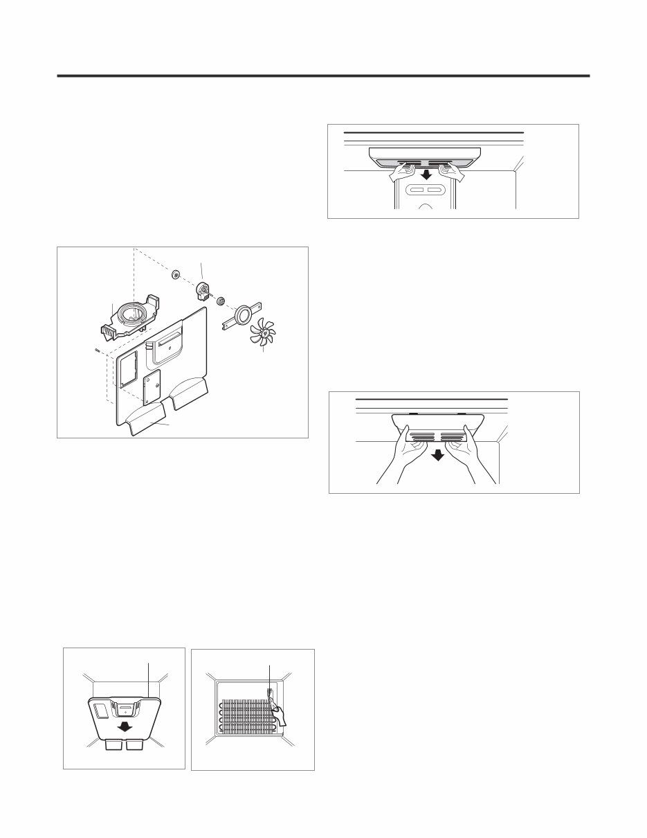
GRILLE ASSEMBLY Fig. 2 DEFROST-CONTROL ASSEMBLY Fig. 3 GRILLE FAN MOTOR BRACKET MOTOR Fig. 1 FAN 3-1 FAN AND FAN MOTOR 1. Remove the freezer shelf. (If your refrigerator has an icemaker, remove the icemaker first). 2. Remove the plastic guide for slides on left side by unscrewing phillips head screws. 3. Remove the grille by removing one screw and pulling the grille forward. 4. Remove the Fan Motor assembly by loosening 2 screw and disassemble the shroud. 5. Pull out the fan and separate the Fan Motor and Bracket. 3-2 DEFROST CONTROL ASSEMBLY Defrost Control assembly consist of Drefrost Sensor and FUSE-M. The Defrost Sensor works to defrost automatically. It is attached to the metal side of the Evaporator and senses its temperature. Fuse-M is safety device for preventing over-heating of the Heater when defrosting. At 72°C, it turns the Defrost Heater off. 1. Pull out the grille assembly. (Figure 2) 2. Separate the connector with the Defrost Control assembly and replace the Defrost Control assembly after cutting the Tie Wrap. (Figure 3) Fig. 4 Fig. 5 1. Unplug the power cord from the outlet. 2. Remove Refrigerator shelves. 3. Release the hooks on both ends of the lamp shield and pull the shield downward to remove it. 4. Turn the lamp counterclockwise. 5. Assemble in reverse order of disassembly. 6. Replacement bulb must be the same specification as the original (Max. 40 W-2EA). 3-3 LAMP 3-3-1 REFRIGERATOR COMPARTMENT LAMP 3-3-2 FREEZER COMPARTMENT LAMP 1. Unplug refrigerator or disconnect power. 2. Reach behind light to remove bulb. 3. Replace bulb with a 60W appliance bulb. 4. Plug in refrigerator or reconnect power. 3. DISASSEMBLY - 7 -
3-5 MULTI DUCT 1. Remove an upper and lower Cap by using a flat screwdriver, and loosen 2 screws. (Figure 7) 2. Disconnect the lead wire on the botton position. 3-4 CONTROL BOX-REFRIGERATOR CONTROL BOX COVER LAMP Fig. 6 1. First, remove all shelves in the refrigerator, than remove the Refrigerator control Box by loosening 2 screws. 2. Remove the Refrigerator Control Box by pulling it downward. 3. Disconnect the lead wire on the right position and separate the lamp sockets. - 8 - Fig. 7
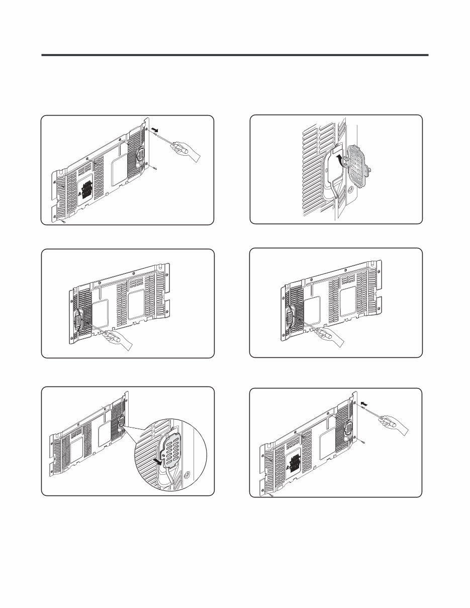
- 9 - 3-6 VALVE COVER 3-6-1 DISASSEMBLE 3-6-2 ASSEMBLE 1. Unscrew the back cover. 2. Unscrew the valve from the back side. cover 3. Push to the left and release. 1. Insert the ribs to the right side of the back hole. cover 2. Screw the valve from the back side. cover 3. Screw the back . cover Fig. 10 Fig. 8 Fig. 9 Fig. 11 Fig. 12 Fig. 13
Are you experiencing issues with your LG Refrigerator? Don't rush to replace it – consider upgrading or repairing it instead! This comprehensive service and repair manual is utilized by Official Certified LG Technicians and is designed to assist you in troubleshooting and fixing your refrigerator.
With this manual, you will gain valuable insights into product specifications, parts identification, disassembly instructions, troubleshooting techniques, adjustment procedures, circuit diagrams, PCB pictures, test mode and diagnostics, operation principle and repair method of the ice maker, descriptions of function, circuits, and error codes, as well as exploded views.
Featuring detailed illustrations and step-by-step instructions, this manual provides the best approach to servicing and repairing your device. Rest assured, this is the official service and repair manual, not a scanned-in or bootlegged copy. It is created in the highest resolution, ensuring excellent print quality for the pages you need.
Print this manual easily from any printer and computer, and enjoy instant access after payment without any shipping fees or waiting for postal delivery. The manual is available in English and consists of 52 pages, compatible with both Windows and MAC platforms.
If you are unable to find a specific service manual, feel free to reach out to us with your request. With the most extensive and comprehensive service manual database, there's a good chance we can assist you!