CAUTION BEFORE SERVICING THE UNIT, READ THE "SAFETY PRECAUTIONS" IN THIS MANUAL. http://biz.lgservice.com MODEL : COLOR : REFRIGERATOR SERVICE MANUAL R ef. No. R ef. No. GBB532**** GBB531**** GBB530**** GBB539**** Ref. No. GBF539**** Ref. No. GBF530**** Downloaded from www.Manualslib.com manuals search engine
- 2 - SAFETY PRECAUTIONS ............................................................................................................ ........................................... 2 SERVICING PRECAUTIONS ................................................................................................................................................... 3 SPECIFICATIONS ................................................................................................................ ................................................ 4-7 PARTS IDENTIFICATION .......................................................................................................... .........................................8-12 INSTRUCTIONS FOR REVERSING DOOR SWING ......................................................................................... ............... 13-15 DISASSEMBLY ................................................................................................................... .............................................. 16-17 DOOR .......................................................................................................................... ...................................................... 16 DOOR SWITCH ................................................................................................................... .............................................. 16 FAN AND FAN MOTOR ............................................................................................................. ........................................ 16 DEFROST CONTROL ASSEMBLY ...................................................................................................... ............................. 17 FREEZER HEATER, SHEATH ........................................................................................................ .................................. 17 COMPRESSOR (A++ and A s) l e d o M + ...................................................................................... ................................... 18 PTC-STARTER (A++ and A+ Models) ...................................................................................... . .................................. 18 OLP (OVER LOAD PROTECTOR) (A++ and A+Models) ....................................................... . .................................. 19 COMPRESSOR .................................................................................................................... .............................................20-28 ADJUSTMENT .................................................................................................................... ............................................. 18-19 INVERTER LINEAR COMPRESSOR . ................................................................................................... .......................20-28 HEAVY REPAIR METHOD OF REFRIGERATOR BY APPLICATION OF REFRIGERANT ........................................... 29-34 OUTLINE ....................................................................................................................... ..................................................... 29 HEAVY REPAIR SVC METHOD ....................................................................................................... ...........................30-34 CIRCUIT DIAGRAM ............................................................................................................... ........................................... 35-4 TROUBLESHOOTING (MECHANICAL PART) ............................................................................................. ....................4 -49 ANOTHER ELECTRIC COMPONENTS ................................................................................................... ......................... 4 PTC AND OLP ..................................................................................................................................................................... 4 COMPRESSOR AND ELECTRIC COMPONENTS ......................................................................................... ......................... 4 SERVICE DIAGNOSIS CHART ....................................................................................................... ..................................4 REFRIGERATING CYCLE ........................................................................................................... ................................4 - MICOM FUNCTION & PCB CIRCUIT EXPLANATION ...................................................................................... .............. 5 -5 MICOM ERROR CODE .............................................................................................................. ....................................... 5 -5 PCB PICTURE ................................................................................................................... ............................................... 5 -6 TROUBLESHOOTING WITH ERROR DISPLAY ............................................................................................ ................. 6 -7 TROUBLESHOOTING WITHOUT ERROR DISPLAY ......................................................................................... ............. 7 -8 REFERENCE ..................................................................................................................... ................................................8 -8 EXPLODED VIEW &REPLACEMENT PARTS LIST ......................................................................................... ............... 8 - P lease read the following instructions before servicing your refrigerator. 1. Check the set for electric losses. 2. Unplug prior to servicing to prevent electric shock. 3. Whenever testing with power on, wear rubber gloves to prevent electric shock. 4. If you use any kind of appliance, check regular current, voltage and capacity. 5. Don't touch metal products in the freezer with wet hands. This may cause frostbite. 6. P revent water from following onto electric elements in the mechanical parts. 7. When standing up after having checked the lower section of the refrigerator with the upper door open, move with care to avoid hitting the upper door. 8. When tilting the set, remove any materials on the set, especially the thin plates(ex. Glass shelf or books.) 9. When servicing the evaporator, wear cotton gloves. 10. Leave the disassembly of the refrigerating cycle to a specialized service center. The gas inside the circuit may pollute the environment. 11. When you discharge the refrigerant, wear the protective safety glasses or goggle for eye safety. 12. When you repair the cycle system in refrigerator, the work area is well ventilated. E specially if the refrigerant is R 600 heat sources. (No smoking) CONTENTS SAFETY PRECAUTIONS Downloaded from www.Manualslib.com manuals search engine
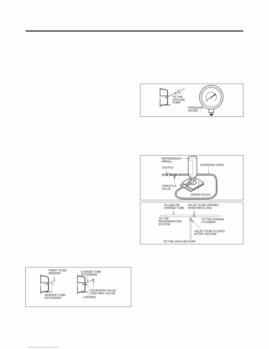
- 3 - Features of refrigerant (R600a) • Achromatic and odor less gas. • Flammable gas and the ignition (explosion) at 494°C . • Upper/lower explosion limit: 1.8%~8.4%/Vol. Features of the R600a refrigerator • C harging of 60% refrigerant compared with a R 134a model. • The suction pressure is below 1bar (abs) during the operation. • Because of its low suction pressure, the external air may flow in the cycle system when the refrigerant leak, and it causes malfunction in the compres s or. • The displacement of compressor using R 600a must be at least 1.7 times larger than that of R 134a. • Any type of dryer is applicable (XH-5, 7, 9). • The E VAPOR ATOR or any other cycle part that has welding joint is hidden in the foam. (If not hidden inside, the whole electric parts must be tested with the LEAKAGE TEST according to the IE C S tandard.) • The compressor has label of the refrigerant R 600a. • Only the SVC man must have an access to the system. After the refrigerant (R 600a) is completely discharged, repair any defective parts and replace the dryer. At any case you must use the LOKR ING for connecting or replacing any part in the cycle (No Fire, No Welding). Charge the N2 gas in order to check for leakage from welding points and the LOKR ING. If leakages are found, repair the defects again. C onnect the S chrader valve to pump with the coupler. And then turn the pump on for vacuum state (F igure 3). Let the pump run until the low pressure gauge indicates the vacuum (gauge pressure -1atm or -760mmHg, absolute pressure 0 ). R ecommended vacuum time is 30 min. After the system is completely vacuumed, fill it with the refrigerant R 600a up to what has been specified at your refrigerator Name Plate. The amount of refrigerant (R 600a) must be precisely measured within the error of ±2g by an electron scale (Figure 4). If you use the manifold connected with both the refrigerant (R 600a) cylinder and the vacuum pump simultaneously, make sure the pump valve is closed (Figure 5). Connect the charging hose (that is connected to the refrigerant (R 600a) cylinder) to the S chrader valve installed on the service tube. Then, charge the refrigerant (R 600a) by controlling the T hrottle valve. When you do so, do not fully open the Throttle valve because it may make damage to the compressor. Gradually charge the refrigerant (R 600a) by changing open and close the Throttle Valve (5g at each time). The charging hose must use a one-way valve to prevent the refrigerant refluence. C lose the S chrader valve cap after the refrigerant (R 600a) is completely recharged. After you completely recharge the refrigerant (R 600a), perform the leakage test by using a portable leakage detector or soapy water. Test the low pressure (suction) parts in compressor off time and high pressure parts in compressor on time. If the leakages are found, restart from the refrigerant (R 600a) discharging process and repairs defects of leaks. After the leakage test, check the temperature of each parts of the cycle. Check with hands if the CONDENSER and the case (HOT-LINE pipe) that is contacted to the door gasket are warm. C onfirm that frost is uniform distributed on the surface of the EVAPORATOR. Installation place • Must be well ventilated. • Must be 20 m 3 or larger. • Must be no-smoking area. • No ignitable factors must be present. Utilities • R efrigerant cylinder (MAX NE T 300g) • Manometer • Vacuum pump (600ℓ /min) • P iercing C lamp • Quick coupler • Hoses (5m-1E A, 1m-3E A) • LOKRING • Portable Leakage detector (3g/year ) • Nitrogen cylinder (for leakage test) • C oncentration gauge Make sure before Servicing • R efrigerant C onfirm the refrigerant by checking Name P late and the label on the compressor, after opening the COVER ASSEMBLY, BACK-M/C. • If the refrigerant is R 600a, you must not weld or apply a heat source. Air R echarging in Compressor Before refilling the refrigerant, you must perform the test according to Chapter 5 (TROUBLESHOOTING CHART). When the defects are found, you must discharge the residual refrigerant (R 600a) in the outdoor. For discharging the refrigerant R 600a, break the narrow portion of tube extension by hand or with a pipe cutter as shown in Figure 1. Leave it for 30min in outside to stabilize the pressure with ambient. Then, check the pressure by piercing the dryer part with piercing pliers. If the refrigerant is not completely discharged, let the refrigerator alone for more 30min in outside. Attach the service tube installed with a S chrader valve (one- way valve) by using the LOKR ING (Figure 2). Then, connect the S chrader valve (one-way valve) to the pump that is connected to the discharging hose leading to the outside. When discharging the residual refrigerant, repeat 3 cycle that includes 3min of the pump running->pump off->30sec of the compres s or running. Figure 1 Figure 2 Figure 3 Figure 4 Figure 5 SERVICING PRECAUTIONS Downloaded from www.Manualslib.com manuals search engine
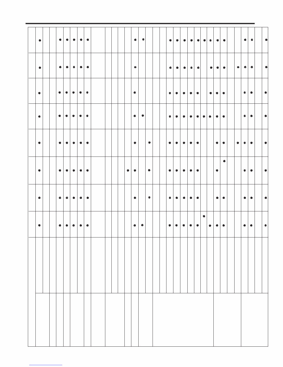
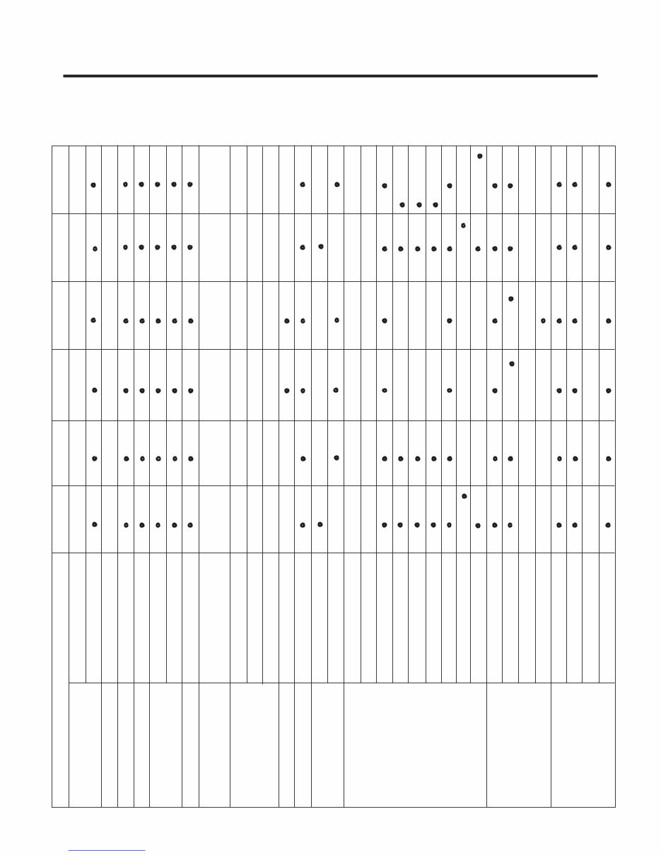
DEFROSTING SYSTEM DEFROSTING DEVICE NET WEIGHT COOLING SYSTEM TEMPERATURE CONTROL REFRIGERANT WEIGHT COMPRESSOR EVAPORATOR CONDENSER REFRIGERATOR COMPARTMENT DOOR BASKET FREEZER COMPARTMENT LUBRICATION OIL DIMENSIONS (mm) - 4 - 1. R ef. No: G B B530*****, G B F530***** ITEMS 595(W) X 2010(H) X 650(D) 595(W) X 1900(H) X 650(D) F an C ooling Micom C ontrol F ull Automatic Heater Defrost Heater, Sheath R 600a HTS55MT S5 HFP 5HFP PTC S tarting Type Pin Tube Type S piral C ondenser Wire Condenser Removable Glass Shelf Vita, LED(1EA) Cover, TV (L) Cover, TV (U) Fresh 0 Zone Magic Crisper (1EA) Vegetable Drawer (1EA) Folding Shelf Bottle Rack E gg T ra y Dairy C orner Basket Water Tank Tray Drawer (3EA) Tray Ice Ice B ox Wire Shelf (2EA) • - - - 3E A(option 2) 3E A(option 2) (option ) (option ) 3E A - G B B 530*** F* • • • • • • • • • • • • • • - • • • • • • • • • • • • • • • • • • • • • • • • • - - - - - - - - - - - - - - 3E A 3E A - - - G B B 530*** P* 67g (FLB124) 67g (FLA102) No (FLA102/BMG089) 67g (FLA102) 61g (BMG089) 57g (BMG089) 61g (BMG089) 63g (CMA089) 61g (CMA089) Yes(CMA089) No (FLA102/BMG089) Yes(CMA089) 65g (FMA102) 120cc(FMA102) 180cc(FLA102) 180cc(FLA102) 150cc(CMA089) 170cc(BMG089) 170cc(BMG089) 170cc(BMG089) 67g (FLA102) 61g (BMG089) 180cc(FLA102) 170cc(BMG089) 67g (FLA102) 61g (BMG089) 63g (CMA089) 180cc(FLA102) 150cc(CMA089) 170cc(BMG089) 150ccCMA089) 175cc(FLB124) 175cc(FLB124) 175cc(FLB124) • • • • • • • • • • • • • • • • • • - - - - - 4E A - - - - G B B 530*** W* • • • • • • • • • • • • • • • • • • • • • • • • • • • • • • - - - - - - - 3E A 2E A 3E A 3E A - • • • - GBF G B B530***X* G B B530***Z* 530*** P* • • • • • 67g - • - • • • • • • • • • • • - - - 2E A 3E A • • • - G B B530***Q* • • • • • 67g - - - - - - - - - - - - - - - - - • • • • • • • • • • - - - 3E A 3E A • • • - • • • • • - G B F530***Z* - - • • • • • • • • • • - - - 3E A 3E A • • • • - • • • • • SPECIFICATIONS Downloaded from www.Manualslib.com manuals search engine
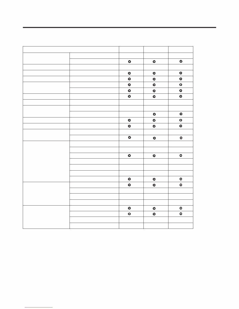
- 5 - 1. R ef. No: GB B539*****, GB F539***** SPECIFICATIONS DEFROSTING SYSTEM DEFROSTING DEVICE NET WEIGHT COOLING SYSTEM TEMPERATURE CONTROL REFRIGERANT WEIGHT COMPRESSOR EVAPORATOR CONDENSER REFRIGERATOR COMPARTMENT DOOR BASKET FREEZER COMPARTMENT LUBRICATION OIL DIMENSIONS (mm) ITEMS 595(W) X 2010(H) X 650(D) 595(W) X 1900(H) X 650(D) F an C ooling Micom C ontrol F ull Automatic Heater Defrost Heater, Sheath R 600a HTS55MT S5 HFP PTC S tarting Type Pin Tube Type S piral C ondens er Wire Condenser Removable Glass Shelf Vita, LED(1EA) Cover, TV (L) Cover, TV (U) Fresh 0 Zone Magic Crisper (1EA) Vegetable Drawer (1EA) Folding Shelf Bottle Rack E gg T ra y Dairy C orner Basket Water Tank Tray Drawer (3EA) Tray Ice Ice B ox Wire Shelf (2EA) • - - - 2E A (option ) (option ) (option ) (option - ) (option - ) (option - ) (option 1) 2E A (option 1) 2E A (option 1) (option 1) 2E A - G B B 539*** F* • • • • • • • • • • • • • • - • • • • • • • • • • • • • • • • • • • • • • • • - - - - - (option ) • - (option ) • - - - - - - - - - 2E A 2E A - - - G B B 539*** P* • • • • • • • • • • • • • • • - - - - - - - - - - - 3E A - - - G B B 539*** W* • • • • • • • • • • • • • • • • • • • • • • • • • • • - - - - - - - - - - - - - - - - - - - - 2E A 3E A 2E A - • • • - GBF G B B539***F* G B B539***Z* 539*** W* • • • • • • - • • • • • • • • • • - - - 2E A (option 1) 2E A • • • - • • • • • 67g (FLB124) 65g (FMA102) 120cc(FMA102) 175cc(FLB124) 67g (FLB124) 65g (FMA102) 120cc(FMA102) 175cc(FLB124) 67g (FLA102) 61g (BMG089) 63g (CMA089) 180cc(FLA102) 150cc(CMA089) 170cc(BMG089) 5HFP 67g (FLA102) 61g (BMG089) 180cc(FLA102) 170cc(BMG089) No (FLA102/BMG089) Yes(CMA089) 57g (BMG089) 61g (CMA089) 57g (BMG089) 61g (CMA089) 170cc(BMG089) 170cc(BMG089) 150ccCMA089) 150ccCMA089) Downloaded from www.Manualslib.com manuals search engine
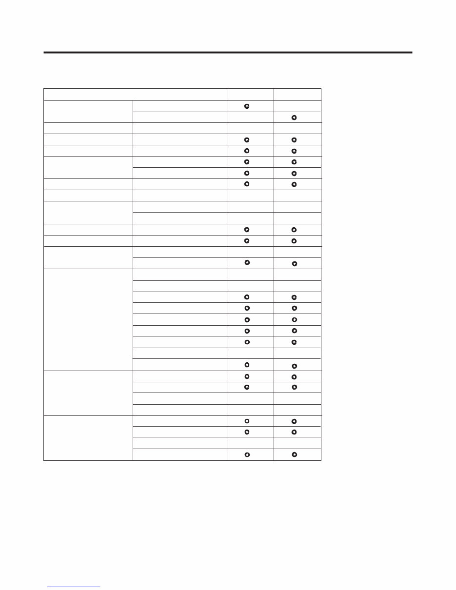
DEFROSTING SYSTEM DEFROSTING DEVICE NET WEIGHT COOLING SYSTEM TEMPERATURE CONTROL REFRIGERANT WEIGHT COMPRESSOR EVAPORATOR CONDENSER REFRIGERATOR COMPARTMENT DOOR BASKET FREEZER COMPARTMENT LUBRICATION OIL DIMENSIONS (mm) - 6 - 1. R ef. No: GB B539*****, GB F539***** ITEMS 595(W) X 2010(H) X 650(D) 595(W) X 1900(H) X 650(D) F an C ooling Micom C ontrol F ull Automatic Heater Defrost Heater, Sheath R 600a PTC S tarting Type Pin Tube Type S piral C ondens er Wire Condenser Removable Glass Shelf Vita, LED(1EA) Cover, TV (L) Cover, TV (U) Fresh 0 Zone Magic Crisper (1EA) Vegetable Drawer (1EA) E gg T ra y Dairy C orner Basket Water Tank Tray Drawer (3EA) Tray Ice Ice B ox Wire S helf (2E A) - - - 3E A 3E A - - - G B B539**HW* • • • • • • • • • • • • • • • • • • • • • • • • • • • • • - - - - - - - - - - - - - - 3E A 3E A - - - G GBB539**HZ* B B 539**HP* 63g - • • • • • • • • • • • • • • • - - - - - - - - - 3E A 3E A - - 67g S5 HFP SPECIFICATIONS 57g (BMG089) 61g (CMA089) 170cc(BMG089) 150cc(CMA089) 5HFP Downloaded from www.Manualslib.com manuals search engine
DEFROSTING SYSTEM DEFROSTING DEVICE NET WEIGHT COOLING SYSTEM TEMPERATURE CONTROL REFRIGERANT WEIGHT COMPRESSOR EVAPORATOR CONDENSER REFRIGERATOR COMPARTMENT DOOR BASKET FREEZER COMPARTMENT LUBRICATION OIL DIMENSIONS (mm) - 7 - 1. R ef. No: GB B530***M*, GB F539***M* ITEMS 595(W) X 2010(H) X 650(D) 595(W) X 1900(H) X 650(D) F an C ooling Micom C ontrol F ull Automatic Heater Defrost Heater, Sheath R 600a HTS55MT PTC S tarting Type Pin Tube Type S piral C ondens er Wire Condenser Removable Glass Shelf Vita, LED(1EA) Cover, TV (L) Cover, TV (U) Fresh 0 Zone Magic Crisper (1EA) Vegetable Drawer (1EA) Folding Shelf Bottel Rack E gg T ra y Dairy C orner Basket Water Tank Tray Drawer (3EA) Tray Ice Ice B ox Wire S helf (2E A) - - - - - 3E A 3E A - G B B530**QM* • • • • • • • • • • • • • • • • • • • • • • • • • • • • • • • • • • • • • • • • - - - - - - 170cc 170cc - 2E A 2E A - - - G B B 539**QM* 61g 61g S5 HFP (5CST) SPECIFICATIONS Downloaded from www.Manualslib.com manuals search engine
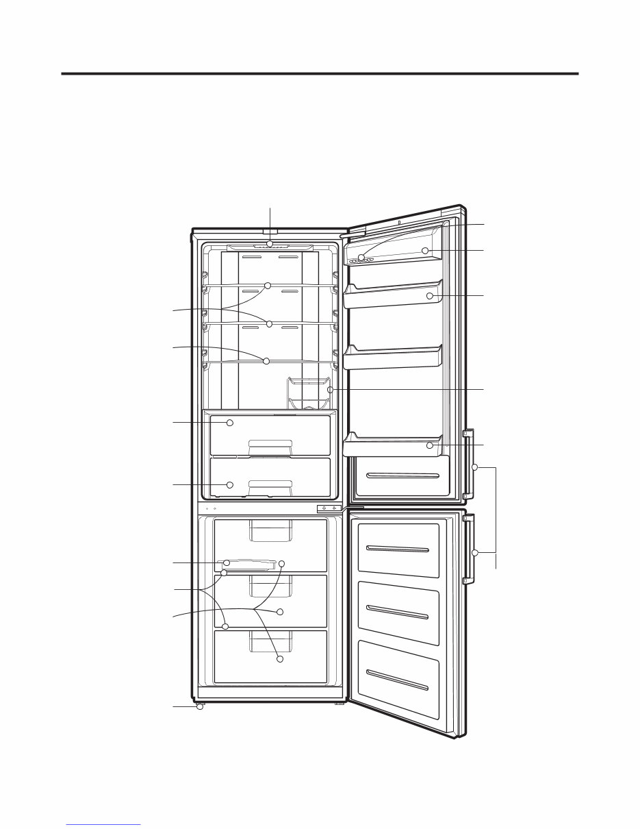
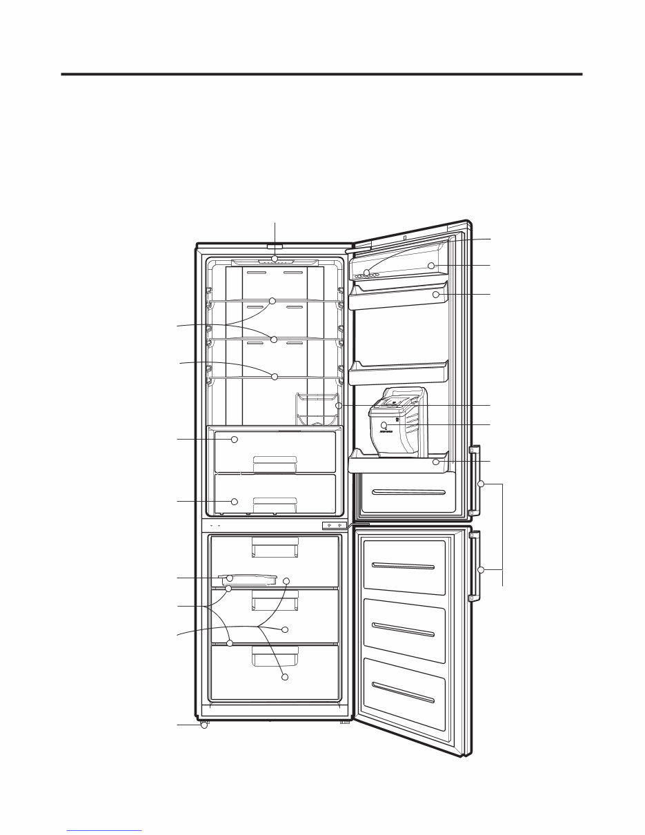
- 8 - G B B530**** Model Name : GBB530**Q**, GBB530**C** PARTS IDENTIFICATION Lamp Removable Glass Shelf Removable Glass Shelf (Folding shelf Optional) Vegetable Drawer (Used to keep fruits and vegetables etc. fresh and crisper) Fresh '0' Zone (Optional) Ice Tray Wire Shelf Freezer Compartment Leveling Screw Basket Door Basket Door Bottle Rack (Optional) Dairy Corner (Optional) Egg Tray (Optional) EZ Open Handle (Optional) Downloaded from www.Manualslib.com manuals search engine
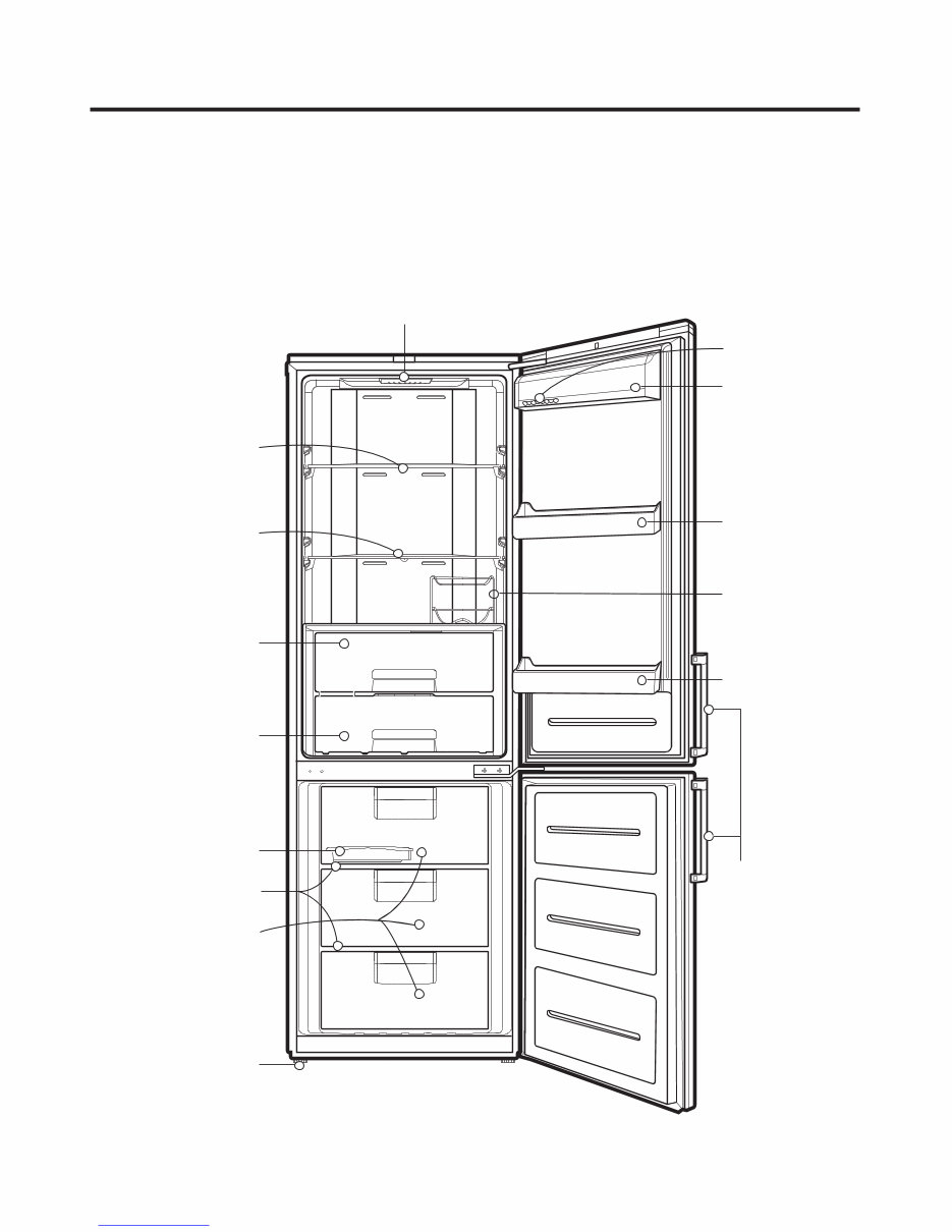
- 9 - GB B530***** Model Name : GBF530**Q** PARTS IDENTIFICATION Lamp Removable Glass Shelf Vegetable Drawer (Used to keep fruits and vegetables etc. fresh and crisper) Fresh '0' Zone (Optional) Ice Tray Wire Shelf Freezer Compartment Leveling Screw Basket Door Water Tank (Optional) Basket Door Dairy Corner (Optional) Egg Tray (Optional) EZ Open Handle (Optional) Bottle Rack (Optional) Removable Glass Shelf (Folding shelf Optional) Downloaded from www.Manualslib.com manuals search engine
- 10 - GB B539***** Model Name : GBB539**QF*, GBB539**QP*, GBB539**CF*, GBB539**CP*, GBB539**CZ*, GBB539**QZ* PARTS IDENTIFICATION Lamp Removable Glass Shelf Vegetable Drawer (Used to keep fruits and vegetables etc. fresh and crisper) Fresh '0' Zone (Optional) Freezer Compartment Leveling Screw Basket Door Basket Door Dairy Corner (Optional) Egg Tray (Optional) Ice Tray Wire Shelf EZ Open Handle (Optional) Bottle Rack (Optional) Removable Glass Shelf (Folding shelf Optional) Downloaded from www.Manualslib.com manuals search engine
This official factory service, repair, and workshop manual for the LG GBB530SWCFE Refrigerator is an essential resource for both professional technicians and DIY enthusiasts. It provides comprehensive guidance for troubleshooting and repairing the refrigerator, covering the following areas:
Product Safety
Servicing Precautions
Specification
Features & Technical Explanation
Exploded View
Troubleshooting Methods
Error Codes
Wiring Diagram
Parts Inspection
Disassembly Instructions
Exploded Views
It is important to note that this is the official service manual in PDF format, ensuring the highest resolution for quality printing. With instant access, there are no shipping fees or waiting time, allowing you to commence repairs promptly. The manual is available in English and consists of 69 pages, compatible with both Windows and MAC platforms.
By utilizing this comprehensive manual, you can be confident in completing repairs, service, and maintenance tasks accurately and efficiently, following the same guidelines used by LG's official technicians and maintenance employees.