

PFAFF Sewing Machine Service & Repair Manual
What's Included?
Fast Download Speeds
Online & Offline Access
Access PDF Contents & Bookmarks
Full Search Facility
Print one or all pages of your manual

How to Repair
PFAFF
How to Repair Sewing machine PFAFF
C PFAFT)

Foreword
This provisional Service Manual has been compiled in order to enable our service
personnel to carry out all repairs on these machines quickly and satisfactorily. It will
be superseded by the final edition when it is published.
Before you carry out any adjustments, acquaint yourself with the settings discussed
in this Manual and check whether the machine is actually out of adjustment. Since,
apart from a few minor details, the mechanical setup of Pfaff machines 1222, 1221,
1212 and 1211 is the same, the instructions contained in this Manual apply to all of
them. Variations in the adjustment procedure which are necessitated by differences
in design are discussed separately.
For checking up or adjusting a machine, it is best to follow the procedure outlined in
the Manual. When re-assembling machines which have been dismantled completely,
roughly adjust all parts in order to facilitate final adjustment. When ordering spare
parts, please refer to the Spare Parts Catalogue and state the following:
1. Machine class
2. Complete ten-digit
3. Part name
4. Color of finish, if part is lacquered.
5. Old or new version, if applicable.
When making electrical repairs, be sure to comply with the safety regulations in
effect in your country. Since part of the electrical system of these machines must
only be tested at low tension, proceed in strict compliance with the instructions given
in the chapter on the "Electrical System". For this reason, all electrical repairs must
be performed by an expert.
Adjustment of the machine is greatly facilitated by the following tools and
gauges:
Needle rise gauge 87O 136-01
C-clamp for above gauge 87O 137-00
Bobbin case position slot gauge 7*501.00-201
Machine feed gauge 63-112 120-08
Special spanner 106 300-306
Combination spanner, 5«5 nun 43-111 010-04
Combination spanner, 7«0 mm 43-111 010-05
Combination spanner, 8 mm 43-111 010-06
Circlip pliers, ZA 21 07-438 000-40
Circlip pliers, A 1 07-438 000-50
Clip washer pliers, 1.9 kz 07-437 003-10
Clip washer pliers, 2.3 kz 07-437 003-20
Clip washer pliers, 3.2 kz 07-437 003-30
Clip washer pliers, 4.0 kz 07-437 003-40
Clip washer pliers, 5.0 kz 07-437 003-50
Clip washer pliers, 6.0 kz 07-437 003-60
Clip washer pliers, 7.0 kz 07-437 003-70

Contents
Page
Foreword 1
Technical Data 5
Stop Matic Mechanism
Operation
1. Adjusting the Clutch Lever 7
2. Sotting the Roller in Relation to the
Roller Clutch Pin 9
Zigzag Mechanism
3. Dismantling the Automatic Mechanism 10
Relative Adjustment of Worm Gears and
of Drive Lever 11
6. Adjusting the Needle Position Knob 12
7. Basic Position of Eccentric Stud in
Needle Bar Frame 13
8. Zeroing the Needle for Straight Stitching 14
9. Adjusting the Needle Vibration Controlled
by the Zigzag Mechanism 15
10. Adjusting the Needle Position 17
11. Centering-The Needle Throw in the
Needle Plate Slot l8
Buttonhole MechanismM 12.
Op
eration of Buttonhole Mechanism 20
13. Basic Position of Buttonhole Control Stop 22
lk. Adjusting the Relative Position of Driving
Pawl and Ratchet Wheel 23
15. Timing the Pawl Stroke 2k
16. Final Adjustment of the Buttonhole
Control Stop 26
17 Timing the Buttonhole Forward-Reverse Feed 28
Feed Mechanism
18. Lateral Adjustment of Feed Dog 29
19. Setting the Feed Dog Parallel to the
Needle Plate 31
20. Setting the Feed Dog at the Correct Height 32
21. Adjusting the Feed Eccentric Clutch Sleeve 33
22. Adjusting the Feed Eccentric Endwise 35
23. Adjusting the Link-Type Feed Regulator
Endwise 36
2k. Zeroing the Feed Regulator 37
25. Timing the Top and Bottom Feed Strokes 38

Page
26. Adjusting the Drop Feed Mechanism 40
27. Setting the Presser Bar at the Correct Height 4l
28. Adjusting the Pressure on the Material 43
29. Lateral Adjustment of Feeding Foot in
Relation to Sewing Foot 44
30. Adjusting the Feeding Foot in Sewing
Direction 46
31. Adjusting the Feeding Foot Vertically 47
32. Adjusting the Vibrator 48
33. Timing the Buttonhole Forward-Reverse Feed 50
Sewing Mechanism
34. Adjusting the Position of the Needle in the
Needle Plate Slot 52
35. Basic Position of Hook Bearing 52
36. Timing the Sewing Hook 53
37. Setting the Needle Bar at the Correct Height 54
38. Setting the Hook-to-Needle Clearance 57
39. Adjusting the Bobbin Case Position Finger 58
Automatic Mechanism
40. Operation 60
41. Fitting the Automatic Mechanism 63
Fixed-Ratio Automatic Mechanism
42. Setting the Clearance between Worm and
Worm Wheel 65
43. Setting the Feeler Fingers Close to the
Cam Stack 66
44. Adjusting the Needle Vibrating Controlled
by the Fixed-Ratio Automatic Mechanism 67
45. Centering the Needle Throw in the Needle
Plate Slot for Functional Stitching 69
46. Adjusting the Length of Forward and Backward
Stitches for Hemstitching 70
..... Variable-Ratio Automatic Mechanism
47. Setting the Feeler Fingers Close to the
Cam Stack 72
48. Zeroing the Pattern Length Wheel 73
49. Close Setting of Feeler Finger for Scallops 74
Electrical System
50. Description of Electrical Equipment 75
51. Setting the Maximum Speed and the Speed for
The Stop matic Control 79
52. Setting the Maximum Speed of Machine and Stop
matic Mechanism on Machines Equipped with
Dual-Voltage-Range Motors (110 and 220 V) 8l
53. Adjusting the Cleaned Belt Tension 8j>
54. Test Procedure and Trouble Shooting in the
Electrical System 84

Page
Sewing Off
5^. Adjusting the Dobbin Winder 85
55. Operation of Needle Threaded 86
56. Adjusting the Threaded Bar Collar 86
57» Adjusting the Needle Threaded Head 87
58. Tension Regulation 88
59* Adjusting the Bobbin Thread Tension 88
60. Adjusting the Needle Thread Tension 89
61. Adjusting the Tension Release Mechanism 90
62. Adjusting the Stroke of the Thread
Check Spring 91
63. Adjusting the Length of Forward and
Backward Stitches for Hemstitching 92
64a. Sitting the Household Overlook Stitch 92 a
6k. Adjusting the Length of Forward and
Backward Stitches for Triple-Stitch Seams 93
65. Making a Sample Various repair jobs Swatch 94
66. Changing the motor and the carbon brushes 95
67. Changing the pressure spring in the
balance-wheel realize Icon 99

Technical Data
Pfaff 1222 free-arm sewing machine with additional top feed
And combined automatic unit consisting of a fixed-ratio functional-stitch
mechanism and a variable-ratio ornamental-stitch mechanism.
Pfaff 1221 flatbed sewing machine with additional top feed
And combined automatic unit consisting of a fixed-ratio functional-stitch
mechanism and a variable-ratio ornamental-stitch mechanism.
Pfaff 1212 free-arm sewing machine with fixed-ratio automatic functional-stitch
mechanism.
Pfaff 1211 flatbed sewing machine with fixed-ratio automatic functional-stitch
mechanism.
Fixed-ratio automatic unit with forward-reverse feed control, reduction ratio 12:1.
Five functional stitches which can be varied by different zigzag settings or combined.
Variable-ratio automatic unit with intermittent drive and stitch number regulation.
Five ornamental stitches which can be varied by different needle position and pattern
length settings or combined. Zigzag mechanism with needle vibration control and
needle position adjustment (left, center, right).
Stitch length and stitch width settings are combined in fixed relationship.
Semi-automatic buttonhole unit with forward-reverse feed control.
Feed eccentric clutch (for reverse sewing and buttonholing). Top and bottom feeds, 1:1
feed ratio, upper feeding foot can be disengaged.
Electronic speed control by thyristor control. Master switch for
electrical system.
Stop matic control with roller clutch for controlling needle position at end of sewing
action.
Drop feed mechanism combined with vibrator for operating the presser bar.
Power is transmitted from the arm shaft to the hook drive shaft by a clip belt at a ratio of
1:2.
Power is transmitted from the motor to the shaft by a cleared belt.
Link take-up.
Vibrating needle bar frame.
Transverse, double-revolution rotary hook. Needle system
130. Light-metal casting.
Weight of machines with motor, but without accessories:
Pfaff 1222 10.20 kg (22.4 lbs)
Pfaff 1221 9.00 kg (19.8 lbs)
Pfaff 1212 9.50 kg (20.9 lbs)
Pfaff 1211 8.35 kg (18.3 lbs)
Stitch length approx. 4 mm (6 s.p.i.) Stitch width
approx. 4.5 mm (11/64")

Clear work space: 225 x 120 mm (9" x 4 3/4") Bedplate dimensions: 421 x 178
mm (15 1/2" x 7") Base plate dimensions on free-arm machines: 421 x 178 mm
(15 1/2" x 7") Motor:
Type GE 270, 220 or 110 V, 0-60 c/s, 40/80 W,
7000 r.p.m. + 10 % Type GE 271,
dual-voltage-range motor for 220 or
110 V connection, 0-60 c/s, 40/80 W,
7000 r.p.m. + 10 % Fully radio and TV
suppressed. Suppression class: FN Sewing head: insulation class
2 Motor alone: insulation class 1 Glare-free sewing light, 15 W.
Finish: light grey (No. 6) Subject to alterations in design and
dimensions.
Various Data
Needle bar rise Hook-to-needle clearance Needle
bar height (top of needle eye to lower edge of
hook point), set with machine set for widest
zigzag stitch and needle on left of its throw.
Clearance between bobbin case position
finger and position slot Feed dog height Foot
lift
Maximum feeding foot rise Final
phase of feed stroke
Lowest position of darning foot
above needle plate level
Maximum sewing speed
Maximum speed of Stop matic mechanism
2.0 mm (.08") 0.1
mm (.004") 0.5 mm
(.02")
0.7 mm (.027") 0.9
mm (.035") 6.5 mm
(.25") 1.2 mm (.05")
0.6 - 0.7 mm (.023"
- .027")
0 - 0.1 mm (.004") 900 -
1000 r.p.m. 120 r.p.m.

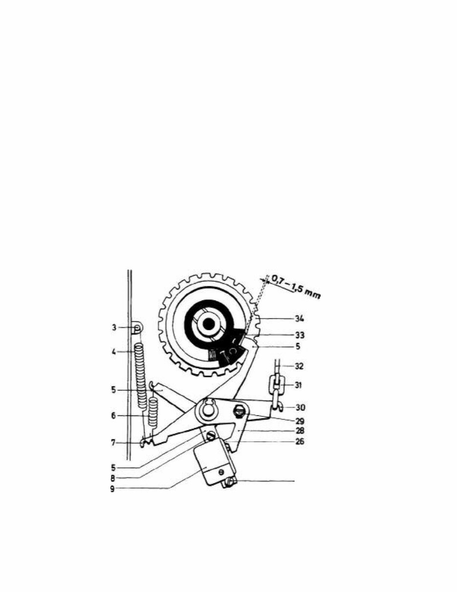
STOPMATIC MECHANISM
Operation
The Stopmatic mechanism is engaged when the presser bar lifter is at its top or
bottom-most position. When this lever is operated, this motion is transmitted to
clutch lever 5 via connecting rod 32 (Fig. l). The clutch lever in turn engages and
disengages a roller clutch. The machine is stopped by the Stopmatic mechanism
when the take-up lever is roughly at its highest point. At this point, clutch lever 5
drops into a cutout in belt sprocket "}k and pushes against slide 33 (with pin).This
slide, in turn, pushes against a roller and thus disengages the roller clutch. Micro
switch 9 is switched off simultaneously.
1. Adjusting the Clutch Lever
Rule:
With the presser bar lifter up in Stopmatic position, there should be a
clearance of 0.7 to 1.5 mm between slide 33 and clutch lever 5, so that when
the presser bar lifter is pushed right down there is a minimum clearance of
0.1 mm. Also, lug 26 of lever 28 (Fig.l) must be in contact with micro switch 9
in both of the above positions of the presser bar lifter.
Check:
Remove the arm standard cover and the balance wheel. Take out the three
screws 37 (Fig.2) and remove cover disc 36. Bring the presser bar lifter to
the upper Stopmatic position and turn the arm shaft in sewing direction
until clutch lever 5 (Fig.la) has dropped into the cutout of upper sprocket 34.
Check the clearance of 0.7 to 1.5 mm (varies on individual machines)
between slide 33 and clutch lever 5. Push the presser bar lifter down as far
as it will go and check the minimum clearance of 0.1 mm, too.
Adjustment:
Push the presser bar lifter back up to the Stopmatic position. Loosen screw
29 and press lever 23 tc the left until the clearance of 0.7 to 1.5 mm is
correct. Fully tighten screw 29.
Verification:
Push the presser bar lifter up beyond its Stop matic position and watch the clearance
while doing so. Push the presser bar lifter down as far as it will go and check the
clearance again. During the longest stroke, there must be a safety clearance of 0.1
mm so that the micro switch is not operated.
Note:
If clutch lever 5 strikes slide 33 when the presser bar lifter is pushed up or down, the
clearance must be repeatedly altered with the presser bar lifter up, until the lever no
longer strikes the slide in the up or down position. It must not be possible for clutch
lever 5 to snap out of the cutout in the upper sprocket when the arm shaft is turned
backwards.
Fig. 1
10
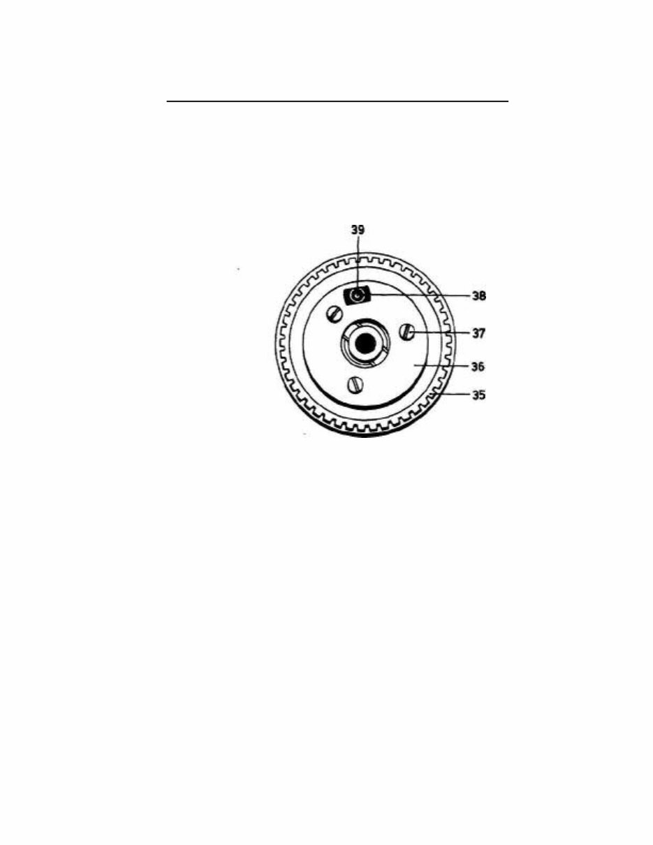
2. Setting the Roller in Relation to the Roller
Clutch Pin ______________________________________
Rule:
Pin 39 on the slide (Fig. 2) should be positioned slightly to the left of the
middle of roller 38.
Check:
Lower the presser bar lifter and turn the balance wheel until roller 38 is
at the top. Make a visual inspection (see Fig. 2).
Fig. 2
Adjustment:
Loosen the three screws 37 and turn the complete roller clutch 35 until
the above setting is correct. Then tighten the three screws 37 securely
again.
Verification:
Operate the Stop matic mechanism several times by flicking the presser
bar lifter to its top and bottom-most positions.
You're Reading a Preview
What's Included?
Fast Download Speeds
Online & Offline Access
Access PDF Contents & Bookmarks
Full Search Facility
Print one or all pages of your manual
$31.99
$41.99
Viewed 94 Times Today


Secure transaction
What's Included?
Fast Download Speeds
Online & Offline Access
Access PDF Contents & Bookmarks
Full Search Facility
Print one or all pages of your manual
$31.99
$41.99
PFAFF Repair Manual
Models Covered
- 1222
- 1221
- 1214
- 1213
- 1212
- 1211
- 1199
- 1197
- 1196


